page 71 NISSAN TIIDA 2008 Service Owner's Guide
[x] Cancel search | Manufacturer: NISSAN, Model Year: 2008, Model line: TIIDA, Model: NISSAN TIIDA 2008Pages: 2771, PDF Size: 60.61 MB
Page 610 of 2771
BL-176
< SERVICE INFORMATION >
TRUNK LID OPENER
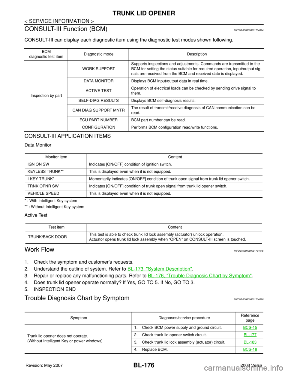
CONSULT-III Function (BCM)
INFOID:0000000001704074
CONSULT-III can display each diagnostic item using the diagnostic test modes shown following.
CONSULT-III APPLICATION ITEMS
Data Monitor
* : With Intelligent Key system
** : Without Intelligent Key system
Active Test
Work FlowINFOID:0000000001704075
1. Check the symptom and customer's requests.
2. Understand the outline of system. Refer to BL-173, "
System Description".
3. Repair or replace any malfunctioning parts. Refer to BL-176, "
Trouble Diagnosis Chart by Symptom".
4. Does trunk lid opener operate normally? If Yes, GO TO 5. If No, GO TO 3.
5. INSPECTION END
Trouble Diagnosis Chart by SymptomINFOID:0000000001704076
BCM
diagnostic test itemDiagnostic mode Description
Inspection by partWORK SUPPORTSupports inspections and adjustments. Commands are transmitted to the
BCM for setting the status suitable for required operation, input/output sig-
nals are received from the BCM and received date is displayed.
DATA MONITOR Displays BCM input/output data in real time.
ACTIVE TESTOperation of electrical loads can be checked by sending drive signal to
them.
SELF-DIAG RESULTS Displays BCM self-diagnosis results.
CAN DIAG SUPPORT MNTRThe result of transmit/receive diagnosis of CAN communication can be
read.
ECU PART NUMBER BCM part number can be read.
CONFIGURATION Performs BCM configuration read/write functions.
Monitor item Content
IGN ON SW Indicates [ON/OFF] condition of ignition switch.
KEYLESS TRUNK** This is displayed even when it is not equipped.
I-KEY TRUNK* Momentarily indicates [ON/OFF] condition of trunk open signal from trunk lid opener switch.
TRNK OPNR SW Indicates [ON/OFF] condition of trunk open signal from trunk lid opener switch.
VEHICLE SPEED This is displayed even when it is not equipped.
Test item Content
TRUNK/BACK DOORThis test is able to check trunk lid lock assembly (actuator) unlock operation.
Actuator opens trunk lid lock assembly when “OPEN” on CONSULT-III screen is touched.
Symptom Diagnoses/service procedureReference
page
Trunk lid opener does not operate.
(Without Intelligent Key or power windows)1. Check BCM power supply and ground circuit.BCS-15
2. Check trunk lid opener switch circuit.BL-177
3. Check trunk lid lock assembly (actuator) circuit.BL-183
4. Replace BCM.BCS-18
Page 611 of 2771
TRUNK LID OPENER
BL-177
< SERVICE INFORMATION >
C
D
E
F
G
H
J
K
L
MA
B
BL
N
O
P
BCM Power Supply and Ground CircuitINFOID:0000000001704077
Refer to BCS-15, "BCM Power Supply and Ground Circuit Inspection".
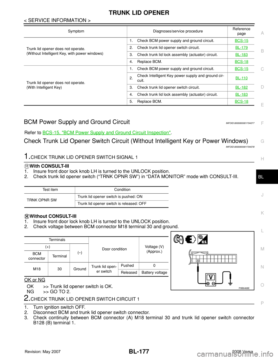
Check Trunk Lid Opener Switch Circuit (Without Intelligent Key or Power Windows)
INFOID:0000000001704078
1.CHECK TRUNK LID OPENER SWITCH SIGNAL 1
With CONSULT-III
1. Insure front door lock knob LH is turned to the UNLOCK position.
2. Check trunk lid opener switch (“TRNK OPNR SW”) in “DATA MONITOR” mode with CONSULT-III.
Without CONSULT-III
1. Insure front door lock knob LH is turned to the UNLOCK position.
2. Check voltage between BCM connector M18 terminal 30 and ground.
OK or NG
OK >> Trunk lid opener switch is OK.
NG >> GO TO 2.
2.CHECK TRUNK LID OPENER SWITCH CIRCUIT 1
1. Turn ignition switch OFF.
2. Disconnect BCM and trunk lid opener switch connector.
3. Check continuity between BCM connector (A) M18 terminal 30 and trunk lid opener switch connector
B128 (B) terminal 1.
Trunk lid opener does not operate.
(Without Intelligent Key, with power windows)1. Check BCM power supply and ground circuit.BCS-152. Check trunk lid opener switch circuit.BL-179
3. Check trunk lid lock assembly (actuator) circuit.BL-183
4. Replace BCM.BCS-18
Trunk lid opener does not operate.
(With Intelligent Key)1. Check BCM power supply and ground circuit.BCS-15
2.Check Intelligent Key power supply and ground cir-
cuit.BL-110
3. Check trunk lid opener switch circuit.BL-182
4. Check trunk lid lock assembly (actuator) circuit.BL-183
5. Replace BCM.BCS-18
Symptom Diagnoses/service procedureReference
page
Test item Condition
TRNK OPNR SWTrunk lid opener switch is pushed: ON
Trunk lid opener switch is released: OFF
Te r m i n a l s
Door conditionVoltage (V)
(Approx.) (+)
(–)
BCM
connectorTe r m i n a l
M18 30 GroundTrunk lid open-
er switchPushed 0
Released Battery voltage
PIIB6468E
Page 648 of 2771
BL-214
< SERVICE INFORMATION >
NATS (NISSAN ANTI-THEFT SYSTEM)
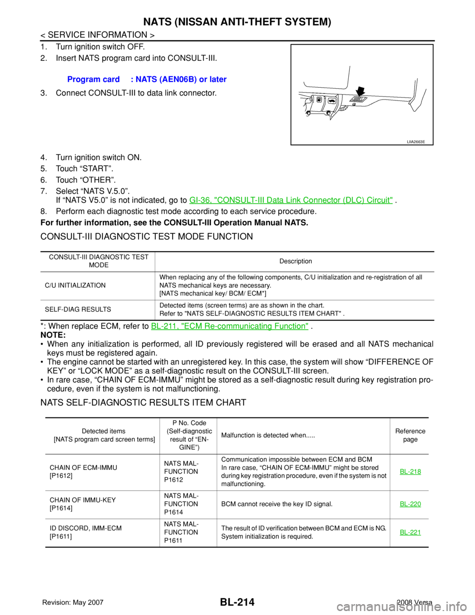
1. Turn ignition switch OFF.
2. Insert NATS program card into CONSULT-III.
3. Connect CONSULT-III to data link connector.
4. Turn ignition switch ON.
5. Touch “START”.
6. Touch “OTHER”.
7. Select “NATS V.5.0”.
If “NATS V5.0” is not indicated, go to GI-36, "
CONSULT-III Data Link Connector (DLC) Circuit" .
8. Perform each diagnostic test mode according to each service procedure.
For further information, see the CONSULT-III Operation Manual NATS.
CONSULT-III DIAGNOSTIC TEST MODE FUNCTION
*: When replace ECM, refer to BL-211, "ECM Re-communicating Function" .
NOTE:
• When any initialization is performed, all ID previously registered will be erased and all NATS mechanical
keys must be registered again.
• The engine cannot be started with an unregistered key. In this case, the system will show “DIFFERENCE OF
KEY” or “LOCK MODE” as a self-diagnostic result on the CONSULT-III screen.
• In rare case, “CHAIN OF ECM-IMMU” might be stored as a self-diagnostic result during key registration pro-
cedure, even if the system is not malfunctioning.
NATS SELF-DIAGNOSTIC RESULTS ITEM CHART
Program card : NATS (AEN06B) or later
LIIA2663E
CONSULT-III DIAGNOSTIC TEST
MODEDescription
C/U INITIALIZATIONWhen replacing any of the following components, C/U initialization and re-registration of all
NATS mechanical keys are necessary.
[NATS mechanical key/ BCM/ ECM*]
SELF-DIAG RESULTSDetected items (screen terms) are as shown in the chart.
Refer to "NATS SELF-DIAGNOSTIC RESULTS ITEM CHART" .
Detected items
[NATS program card screen terms]P No. Code
(Self-diagnostic
result of “EN-
GINE”)Malfunction is detected when.....Reference
page
CHAIN OF ECM-IMMU
[P1612]NATS MAL-
FUNCTION
P1612Communication impossible between ECM and BCM
In rare case, “CHAIN OF ECM-IMMU” might be stored
during key registration procedure, even if the system is not
malfunctioning.BL-218
CHAIN OF IMMU-KEY
[P1614]NATS MAL-
FUNCTION
P1614BCM cannot receive the key ID signal.BL-220
ID DISCORD, IMM-ECM
[P1611]NATS MAL-
FUNCTION
P1611The result of ID verification between BCM and ECM is NG.
System initialization is required.BL-221
Page 649 of 2771
NATS (NISSAN ANTI-THEFT SYSTEM)
BL-215
< SERVICE INFORMATION >
C
D
E
F
G
H
J
K
L
MA
B
BL
N
O
P
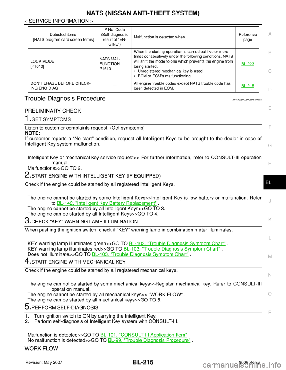
Trouble Diagnosis ProcedureINFOID:0000000001704110
PRELIMINARY CHECK
1.GET SYMPTOMS
Listen to customer complaints request. (Get symptoms)
NOTE:
If customer reports a “No start” condition, request all Intelligent Keys to be brought to the dealer in case of
Intelligent Key system malfunction.
Intelligent Key or mechanical key service request>> For further information, refer to CONSULT-III operation
manual.
Malfunctions>>GO TO 2.
2.START ENGINE WITH INTELLIGENT KEY (IF EQUIPPED)
Check if the engine could be started by all registered Intelligent Keys.
The engine cannot be started by some Intelligent Keys>>Intelligent Key is low battery or malfunction. Refer
to BL-142, "
Intelligent Key Battery Replacement" .
The engine cannot be started by all Intelligent Keys>>GO TO 3.
The engine can be started by all Intelligent Keys>>GO TO 4.
3.CHECK “KEY” WARNING LAMP ILLUMINATION
When pushing the ignition switch, check if “KEY” warning lamp in combination meter illuminates.
KEY warning lamp illuminates green>>GO TO BL-103, "
Trouble Diagnosis Symptom Chart" .
KEY warning lamp illuminates red>>GO TO BL-103, "
Trouble Diagnosis Symptom Chart" .
Does not illuminate>>GO TO BL-103, "
Trouble Diagnosis Symptom Chart" .
4.START ENGINE WITH MECHANICAL KEY
Check if the engine could be started by all registered mechanical keys.
The engine can not be started by some mechanical keys>>Register mechanical key. Refer to CONSULT-III
operation manual.
The engine cannot be started by all mechanical keys>> "WORK FLOW" .
The engine can be started by all mechanical keys>>GO TO 5.
5.PERFORM SELF-DIAGNOSIS
1. Turn ignition switch to ON by carrying the Intelligent Key.
2. Perform self-diagnosis of Intelligent Key system with CONSULT-III.
Malfunction is detected>>GO TO BL-101, "
CONSULT-III Application Item" .
No malfunction is detected>>GO TO BL-99, "
Trouble Diagnosis Procedure" .
WORK FLOW
LOCK MODE
[P1610]NATS MAL-
FUNCTION
P1610When the starting operation is carried out five or more
times consecutively under the following conditions, NATS
will shift the mode to one which prevents the engine from
being started.
• Unregistered mechanical key is used.
• BCM or ECM’s malfunctioning.BL-223
DON'T ERASE BEFORE CHECK-
ING ENG DIAG—All engine trouble codes except NATS trouble code has
been detected in ECM.BL-215
Detected items
[NATS program card screen terms]P No. Code
(Self-diagnostic
result of “EN-
GINE”)Malfunction is detected when.....Reference
page
Page 652 of 2771
BL-218
< SERVICE INFORMATION >
NATS (NISSAN ANTI-THEFT SYSTEM)
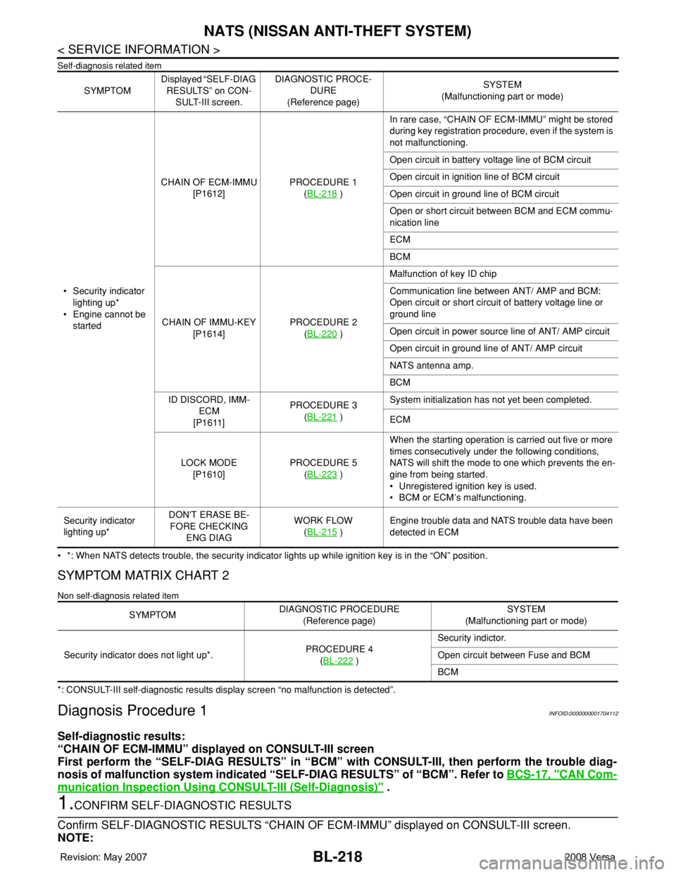
Self-diagnosis related item
• *: When NATS detects trouble, the security indicator lights up while ignition key is in the “ON” position.
SYMPTOM MATRIX CHART 2
Non self-diagnosis related item
*: CONSULT-III self-diagnostic results display screen “no malfunction is detected”.
Diagnosis Procedure 1INFOID:0000000001704112
Self-diagnostic results:
“CHAIN OF ECM-IMMU” displayed on CONSULT-III screen
First perform the “SELF-DIAG RESULTS” in “BCM” with CONSULT-III, then perform the trouble diag-
nosis of malfunction system indicated “SELF-DIAG RESULTS” of “BCM”. Refer to BCS-17, "
CAN Com-
munication Inspection Using CONSULT-III (Self-Diagnosis)" .
1.CONFIRM SELF-DIAGNOSTIC RESULTS
Confirm SELF-DIAGNOSTIC RESULTS “CHAIN OF ECM-IMMU” displayed on CONSULT-III screen.
NOTE:
SYMPTOMDisplayed “SELF-DIAG
RESULTS” on CON-
SULT-III screen.DIAGNOSTIC PROCE-
DURE
(Reference page)SYSTEM
(Malfunctioning part or mode)
• Security indicator
lighting up*
• Engine cannot be
startedCHAIN OF ECM-IMMU
[P1612]PROCEDURE 1
(BL-218
)In rare case, “CHAIN OF ECM-IMMU” might be stored
during key registration procedure, even if the system is
not malfunctioning.
Open circuit in battery voltage line of BCM circuit
Open circuit in ignition line of BCM circuit
Open circuit in ground line of BCM circuit
Open or short circuit between BCM and ECM commu-
nication line
ECM
BCM
CHAIN OF IMMU-KEY
[P1614]PROCEDURE 2
(BL-220
)Malfunction of key ID chip
Communication line between ANT/ AMP and BCM:
Open circuit or short circuit of battery voltage line or
ground line
Open circuit in power source line of ANT/ AMP circuit
Open circuit in ground line of ANT/ AMP circuit
NATS antenna amp.
BCM
ID DISCORD, IMM-
ECM
[P1611]PROCEDURE 3
(BL-221
)System initialization has not yet been completed.
ECM
LOCK MODE
[P1610]PROCEDURE 5
(BL-223
)When the starting operation is carried out five or more
times consecutively under the following conditions,
NATS will shift the mode to one which prevents the en-
gine from being started.
• Unregistered ignition key is used.
• BCM or ECM’s malfunctioning.
Security indicator
lighting up*DON'T ERASE BE-
FORE CHECKING
ENG DIAGWORK FLOW
(BL-215
)Engine trouble data and NATS trouble data have been
detected in ECM
SYMPTOMDIAGNOSTIC PROCEDURE
(Reference page)SYSTEM
(Malfunctioning part or mode)
Security indicator does not light up*.PROCEDURE 4
(BL-222
)Security indictor.
Open circuit between Fuse and BCM
BCM
Page 735 of 2771
BR-4
< SERVICE INFORMATION >
NOISE, VIBRATION AND HARSHNESS (NVH) TROUBLESHOOTING
NOISE, VIBRATION AND HARSHNESS (NVH) TROUBLESHOOTING
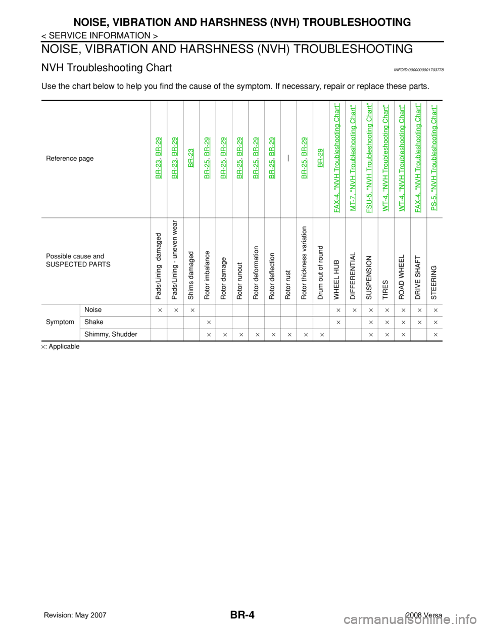
NVH Troubleshooting ChartINFOID:0000000001703778
Use the chart below to help you find the cause of the symptom. If necessary, repair or replace these parts.
×: ApplicableReference page
BR-23
, BR-29
BR-23
, BR-29BR-23
BR-25
, BR-29
BR-25
, BR-29
BR-25
, BR-29
BR-25
, BR-29
BR-25
, BR-29—
BR-25, BR-29BR-29
FAX-4, "
NVH Troubleshooting Chart
"
MT-7, "
NVH Troubleshooting Chart
"
FSU-5, "
NVH Troubleshooting Chart
"
WT-4, "
NVH Troubleshooting Chart
"
WT-4, "
NVH Troubleshooting Chart
"
FAX-4, "
NVH Troubleshooting Chart
"
PS-5, "
NVH Troubleshooting Chart
"
Possible cause and
SUSPECTED PARTS
Pads/Lining damaged
Pads/Lining - uneven wear
Shims damaged
Rotor imbalance
Rotor damage
Rotor runout
Rotor deformation
Rotor deflection
Rotor rust
Rotor thickness variation
Drum out of round
WHEEL HUB
DIFFERENTIAL
SUSPENSION
TIRES
ROAD WHEEL
DRIVE SHAFT
STEERING
SymptomNoise××× ×××××××
Shake× × ×××××
Shimmy, Shudder×××××××× ××× ×
Page 770 of 2771
![NISSAN TIIDA 2008 Service Owners Guide SYSTEM DESCRIPTION
BRC-5
< SERVICE INFORMATION >[ABS]
C
D
E
G
H
I
J
K
L
MA
B
BRC
N
O
P
SYSTEM DESCRIPTION
System ComponentINFOID:0000000001703825
ABS FunctionINFOID:0000000001703826
• The Anti-Lock NISSAN TIIDA 2008 Service Owners Guide SYSTEM DESCRIPTION
BRC-5
< SERVICE INFORMATION >[ABS]
C
D
E
G
H
I
J
K
L
MA
B
BRC
N
O
P
SYSTEM DESCRIPTION
System ComponentINFOID:0000000001703825
ABS FunctionINFOID:0000000001703826
• The Anti-Lock](/img/5/57399/w960_57399-769.png)
SYSTEM DESCRIPTION
BRC-5
< SERVICE INFORMATION >[ABS]
C
D
E
G
H
I
J
K
L
MA
B
BRC
N
O
P
SYSTEM DESCRIPTION
System ComponentINFOID:0000000001703825
ABS FunctionINFOID:0000000001703826
• The Anti-Lock Brake System detects wheel revolution while braking and improves handling stability during
sudden braking by electrically preventing wheel lockup. Maneuverability is also improved for avoiding obsta-
cles during emergency braking.
• If the electrical system malfunctions, the Fail-Safe function is activated, the ABS becomes inoperative and
the ABS warning lamp turns on.
• The electrical system can be diagnosed using CONSULT-III.
• During ABS operation, the brake pedal may vibrate lightly and a mechanical noise may be heard. This is
normal.
• Just after starting the vehicle, the brake pedal may vibrate or motor operating noises may be heard from the
engine compartment. This is normal due to the self check operation.
• Stopping distance may be longer than that of vehicles without ABS when vehicle drives on rough, gravel, or
snow-covered (fresh, deep snow) roads.
EBD FunctionINFOID:0000000001703827
• Electronic Brake Distribution is a function that detects subtle slippages between the front and rear wheels
during braking, and it improves handling stability by electronically controlling the brake fluid pressure which
results in reduced rear wheel slippage.
• If the electrical system malfunctions, the Fail-Safe function is activated, the EBD and ABS become inopera-
tive, and the ABS warning lamp and brake warning lamp are turned on.
• The electrical system can be diagnosed using CONSULT-III.
• During EBD operation, the brake pedal may vibrate lightly and a mechanical noise may be heard. This is
normal.
• Just after starting the vehicle, the brake pedal may vibrate or motor operating noises may be heard from the
engine compartment. This is normal due to the self check operation.
Fail-Safe FunctionINFOID:0000000001703828
CAUTION:
If the Fail-Safe function is activated, perform the Self Diagnosis for ABS system.
ABS/EBD SYSTEM
In case of an electrical malfunction with the ABS, the ABS warning lamp will turn on. In case of an electrical
malfunction with the EBD system, the brake warning lamp and the ABS warning lamp will turn on.
The system will revert to one of the following conditions of the Fail-Safe function.
1. For ABS malfunction, only the EBD is operative and the condition of the vehicle is the same condition of
vehicles without ABS system.
WFIA0118E
Page 805 of 2771

CL-4
< SERVICE INFORMATION >
NOISE, VIBRATION AND HARSHNESS (NVH) TROUBLESHOOTING
NOISE, VIBRATION AND HARSHNESS (NVH) TROUBLESHOOTING
NVH Troubleshooting ChartINFOID:0000000001703116
Use the chart below to help you find the cause of the symptom. The numbers indicate the order of the inspec-
tion. If necessary, repair or replace these parts.
Reference pageCL-5CL-8EM-72CL-11CL-13EM-93
SUSPECTED PARTS (Possible cause)
CLUTCH PEDAL (Inspection and adjustment)
CLUTCH LINE (Air in line)
ENGINE MOUNTING (Loose)
CSC (Concentric slave cylinder) (Worn, dirty or damaged)
CLUTCH DISC (Out of true)
CLUTCH DISC (Runout is excessive)
CLUTCH DISC (Lining broken)
CLUTCH DISC (Dirty or burned)
CLUTCH DISC (Oily)
CLUTCH DISC (Worn out)
CLUTCH DISC (Hardened)
CLUTCH DISC (Lack of spline grease)
DIAPHRAGM SPRING (Damaged)
DIAPHRAGM SPRING (Out of tip alignment)
PRESSURE PLATE (Distortion)
FLYWHEEL (Distortion)
SymptomClutch grabs/chatters 1 2 2 2 2 2
Clutch pedal spongy 1
Clutch noisy 1
Clutch slips 1 2 2 3 4 5
Clutch does not disengage 12 55555 5667
Page 844 of 2771
INDEX FOR DTC
CVT-5
< SERVICE INFORMATION >
D
E
F
G
H
I
J
K
L
MA
B
CVT
N
O
P
SERVICE INFORMATION
INDEX FOR DTC
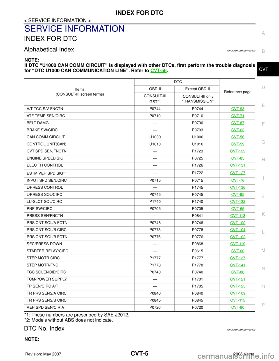
Alphabetical IndexINFOID:0000000001703422
NOTE:
If DTC “U1000 CAN COMM CIRCUIT” is displayed with other DTCs, first perform the trouble diagnosis
for “DTC U1000 CAN COMMUNICATION LINE”. Refer to CVT-56
.
*1: These numbers are prescribed by SAE J2012.
*2: Models without ABS does not indicate.
DTC No. IndexINFOID:0000000001703423
NOTE:
Items
(CONSULT-III screen terms) DTC
Reference page OBD-II Except OBD-II
CONSULT-III
GST*
1 CONSULT-III only
“TRANSMISSION”
A/T TCC S/V FNCTN P0744 P0744 CVT-93
ATF TEMP SEN/CIRC P0710 P0710CVT-71
BELT DAMG — P0730CVT-87
BRAKE SW/CIRC — P0703CVT-63
CAN COMM CIRCUIT U1000 U1000CVT-56
CONTROL UNIT(CAN) U1010 U1010CVT-59
CVT SPD SEN/FNCTN — P1723CVT-129
ENGINE SPEED SIG — P0725CVT-85
ELEC TH CONTROL — P1726CVT-131
ESTM VEH SPD SIG*2— P1722CVT-127
INPUT SPD SEN/CIRC P0715 P0715CVT-76
L/PRESS CONTROL — P1745CVT-136
L/PRESS SOL/CIRC P0745 P0745CVT-95
LU-SLCT SOL/CIRC P1740 P1740CVT-132
PNP SW/CIRC P0705 P0705CVT-65
PRESS SEN/FNCTN — P0841CVT-113
PRS CNT SOL/A FCTN P0746 P0746CVT-100
PRS CNT SOL/B CIRC P0778 P0778CVT-104
PRS CNT SOL/B FCTN P0776 P0776CVT-102
SEC/PRESS DOWN — P0868CVT-119
STARTER RELAY/CIRC — P0615CVT-60
STEP MOTR CIRC P1777 P1777CVT-137
STEP MOTR/FNC P1778 P1778CVT-141
TCC SOLENOID/CIRC P0740 P0740CVT-88
TCM-POWER SUPPLY — P1701CVT-121
TP SEN/CIRC A/T — P1705CVT-125
TR PRS SENS/A CIRC P0840 P0840CVT-109
TR PRS SENS/B CIRC P0845 P0845CVT-115
VEH SPD SEN/CIR AT P0720 P0720CVT-80
Page 845 of 2771
CVT-6
< SERVICE INFORMATION >
INDEX FOR DTC
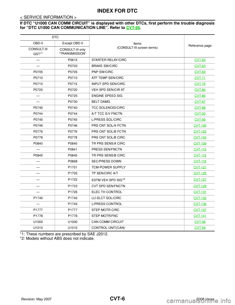
If DTC “U1000 CAN COMM CIRCUIT” is displayed with other DTCs, first perform the trouble diagnosis
for “DTC U1000 CAN COMMUNICATION LINE”. Refer to CVT-56
.
*1: These numbers are prescribed by SAE J2012.
*2: Models without ABS does not indicate.
DTC
Items
(CONSULT-III screen terms)Reference page OBD-II Except OBD-II
CONSULT-III
GST*
1CONSULT-III only
“TRANSMISSION”
— P0615 STARTER RELAY/CIRCCVT-60
— P0703 BRAKE SW/CIRCCVT-63
P0705 P0705 PNP SW/CIRCCVT-65
P0710 P0710 ATF TEMP SEN/CIRCCVT-71
P0715 P0715 INPUT SPD SEN/CIRCCVT-76
P0720 P0720 VEH SPD SEN/CIR ATCVT-80
— P0725 ENGINE SPEED SIGCVT-85
— P0730 BELT DAMGCVT-87
P0740 P0740 TCC SOLENOID/CIRCCVT-88
P0744 P0744 A/T TCC S/V FNCTNCVT-93
P0745 P0745 L/PRESS SOL/CIRCCVT-95
P0746 P0746 PRS CNT SOL/A FCTNCVT-100
P0776 P0776 PRS CNT SOL/B FCTNCVT-102
P0778 P0778 PRS CNT SOL/B CIRCCVT-104
P0840 P0840 TR PRS SENS/A CIRCCVT-109
— P0841 PRESS SEN/FNCTNCVT-113
P0845 P0845 TR PRS SENS/B CIRCCVT-115
— P0868 SEC/PRESS DOWNCVT-119
— P1701 TCM-POWER SUPPLYCVT-121
— P1705 TP SEN/CIRC A/TCVT-125
— P1722
ESTM VEH SPD SIG*2CVT-127
— P1723 CVT SPD SEN/FNCTNCVT-129
— P1726 ELEC TH CONTROLCVT-131
P1740 P1740 LU-SLCT SOL/CIRCCVT-132
— P1745 L/PRESS CONTROLCVT-136
P1777 P1777 STEP MOTR CIRCCVT-137
P1778 P1778 STEP MOTR/FNCCVT-141
U1000 U1000 CAN COMM CIRCUITCVT-56
U1010 U1010 CONTROL UNIT(CAN)CVT-59