wheel torque NISSAN TIIDA 2008 Service Repair Manual
[x] Cancel search | Manufacturer: NISSAN, Model Year: 2008, Model line: TIIDA, Model: NISSAN TIIDA 2008Pages: 2771, PDF Size: 60.61 MB
Page 44 of 2771
AT-32
< SERVICE INFORMATION >
A/T CONTROL SYSTEM
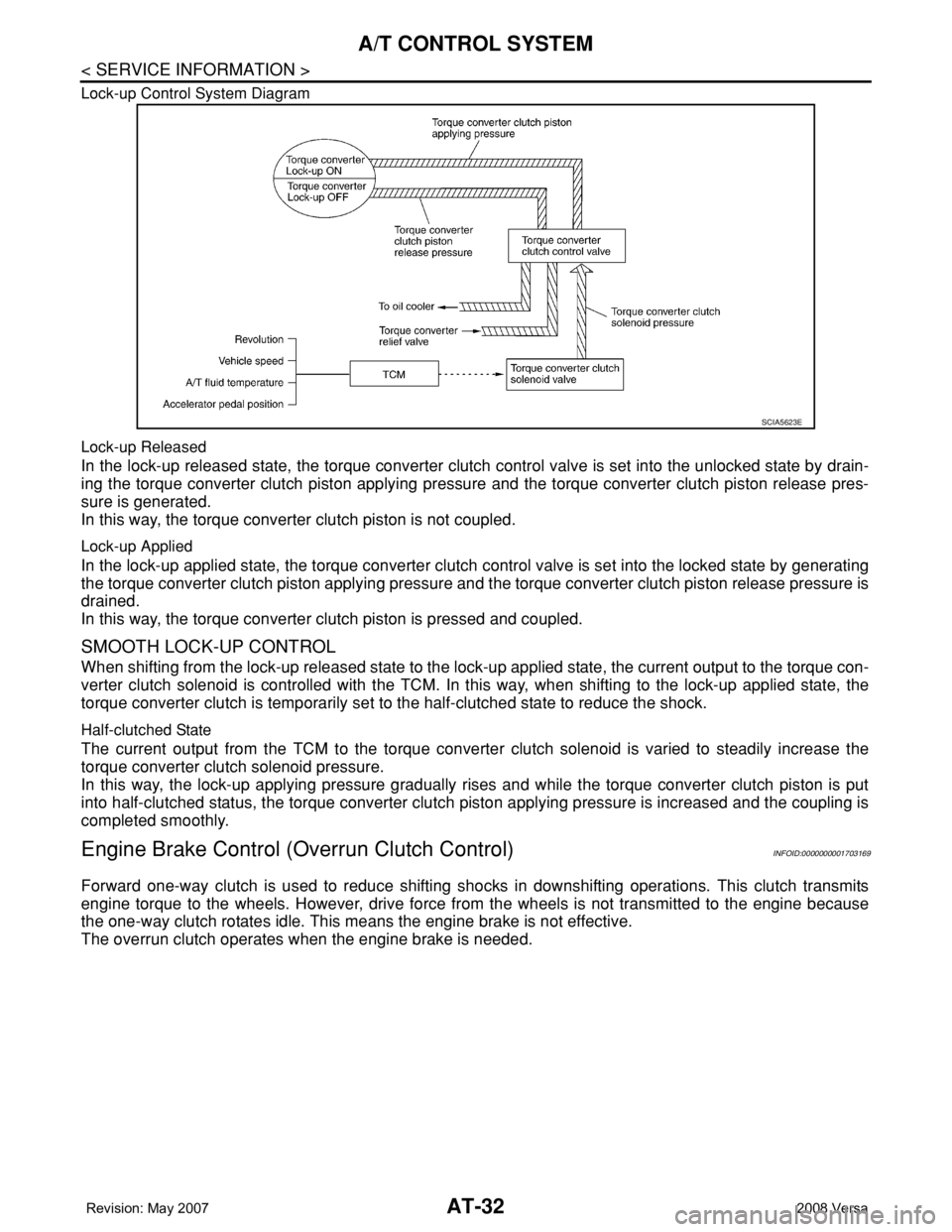
Lock-up Control System Diagram
Lock-up Released
In the lock-up released state, the torque converter clutch control valve is set into the unlocked state by drain-
ing the torque converter clutch piston applying pressure and the torque converter clutch piston release pres-
sure is generated.
In this way, the torque converter clutch piston is not coupled.
Lock-up Applied
In the lock-up applied state, the torque converter clutch control valve is set into the locked state by generating
the torque converter clutch piston applying pressure and the torque converter clutch piston release pressure is
drained.
In this way, the torque converter clutch piston is pressed and coupled.
SMOOTH LOCK-UP CONTROL
When shifting from the lock-up released state to the lock-up applied state, the current output to the torque con-
verter clutch solenoid is controlled with the TCM. In this way, when shifting to the lock-up applied state, the
torque converter clutch is temporarily set to the half-clutched state to reduce the shock.
Half-clutched State
The current output from the TCM to the torque converter clutch solenoid is varied to steadily increase the
torque converter clutch solenoid pressure.
In this way, the lock-up applying pressure gradually rises and while the torque converter clutch piston is put
into half-clutched status, the torque converter clutch piston applying pressure is increased and the coupling is
completed smoothly.
Engine Brake Control (Overrun Clutch Control)INFOID:0000000001703169
Forward one-way clutch is used to reduce shifting shocks in downshifting operations. This clutch transmits
engine torque to the wheels. However, drive force from the wheels is not transmitted to the engine because
the one-way clutch rotates idle. This means the engine brake is not effective.
The overrun clutch operates when the engine brake is needed.
SCIA5623E
Page 701 of 2771
BODY REPAIR
BL-267
< SERVICE INFORMATION >
C
D
E
F
G
H
J
K
L
MA
B
BL
N
O
P
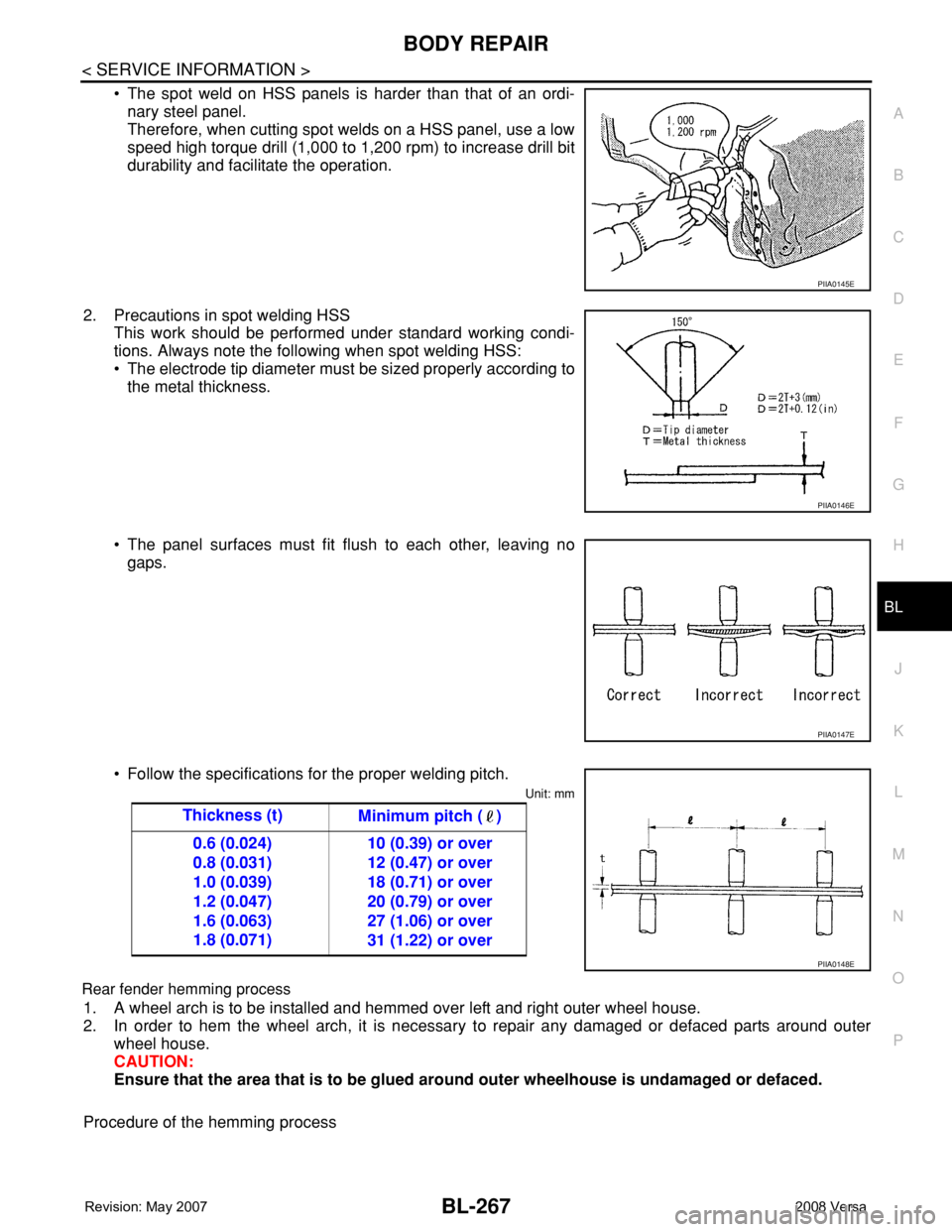
• The spot weld on HSS panels is harder than that of an ordi-
nary steel panel.
Therefore, when cutting spot welds on a HSS panel, use a low
speed high torque drill (1,000 to 1,200 rpm) to increase drill bit
durability and facilitate the operation.
2. Precautions in spot welding HSS
This work should be performed under standard working condi-
tions. Always note the following when spot welding HSS:
• The electrode tip diameter must be sized properly according to
the metal thickness.
• The panel surfaces must fit flush to each other, leaving no
gaps.
• Follow the specifications for the proper welding pitch.
Unit: mm
Rear fender hemming process
1. A wheel arch is to be installed and hemmed over left and right outer wheel house.
2. In order to hem the wheel arch, it is necessary to repair any damaged or defaced parts around outer
wheel house.
CAUTION:
Ensure that the area that is to be glued around outer wheelhouse is undamaged or defaced.
Procedure of the hemming process
PIIA0145E
PIIA0146E
PIIA0147E
Thickness (t)
Minimum pitch ( )
0.6 (0.024)
0.8 (0.031)
1.0 (0.039)
1.2 (0.047)
1.6 (0.063)
1.8 (0.071)10 (0.39) or over
12 (0.47) or over
18 (0.71) or over
20 (0.79) or over
27 (1.06) or over
31 (1.22) or over
PIIA0148E
Page 733 of 2771

BR-2
< SERVICE INFORMATION >
PRECAUTIONS
SERVICE INFORMATION
PRECAUTIONS
Precaution for Supplemental Restraint System (SRS) "AIR BAG" and "SEAT BELT
PRE-TENSIONER"
INFOID:0000000001703775
The Supplemental Restraint System such as “AIR BAG” and “SEAT BELT PRE-TENSIONER”, used along
with a front seat belt, helps to reduce the risk or severity of injury to the driver and front passenger for certain
types of collision. This system includes seat belt switch inputs and dual stage front air bag modules. The SRS
system uses the seat belt switches to determine the front air bag deployment, and may only deploy one front
air bag, depending on the severity of a collision and whether the front occupants are belted or unbelted.
Information necessary to service the system safely is included in the SRS and SB section of this Service Man-
ual.
WARNING:
• To avoid rendering the SRS inoperative, which could increase the risk of personal injury or death in
the event of a collision which would result in air bag inflation, all maintenance must be performed by
an authorized NISSAN/INFINITI dealer.
• Improper maintenance, including incorrect removal and installation of the SRS, can lead to personal
injury caused by unintentional activation of the system. For removal of Spiral Cable and Air Bag
Module, see the SRS section.
• Do not use electrical test equipment on any circuit related to the SRS unless instructed to in this
Service Manual. SRS wiring harnesses can be identified by yellow and/or orange harnesses or har-
ness connectors.
Precaution for Brake SystemINFOID:0000000001703776
• Refill using recommended brake fluid. Refer to MA-10.
• Never reuse drained brake fluid.
• Be careful not to splash brake fluid on painted surface of body. If brake fluid is splashed on painted surfaces
of body immediately wipe it off with cloth and then wash it away with water.
• To clean or wash all parts of master cylinder, disc brake caliper and wheel cylinder, use new brake fluid.
• Never use mineral oils such as gasoline or kerosene. They will ruin rubber parts of the hydraulic system.
• Use a flare nut wrench when removing a brake tube and use a
flare nut torque wrench when installing a brake tube.
• When installing brake tubes and hoses, be sure to check torque.
• Before working, turn ignition switch OFF and disconnect connec-
tors of ABS actuator and electric unit (control unit) or the battery
cable from the negative terminal.
• Burnish the new braking surfaces after refinishing or replacing
drums or rotors, after replacing pads or linings, or if a soft pedal
occurs at very low mileage. Refer toBR-28, "
Brake Burnishing
Procedure" .
SBR686C
Page 756 of 2771
FRONT DISC BRAKE
BR-25
< SERVICE INFORMATION >
C
D
E
G
H
I
J
K
L
MA
B
BR
N
O
P
Removal and Installation of Brake Caliper AssemblyINFOID:0000000001703799
REMOVAL
1. Remove tires from vehicle.
2. Secure disc rotor using wheel nuts.
CAUTION:
Put matching marks on wheel hub assembly and disc rotor, if it is necessary to remove disc rotor.
3. Drain brake fluid. Refer to BR-8, "
Drain and Refill" .
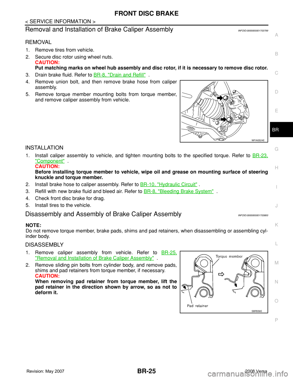
4. Remove union bolt, and then remove brake hose from caliper
assembly.
5. Remove torque member mounting bolts from torque member,
and remove caliper assembly from vehicle.
INSTALLATION
1. Install caliper assembly to vehicle, and tighten mounting bolts to the specified torque. Refer to BR-23,
"Component" .
CAUTION:
Before installing torque member to vehicle, wipe oil and grease on mounting surface of steering
knuckle and torque member.
2. Install brake hose to caliper assembly. Refer to BR-10, "
Hydraulic Circuit" .
3. Refill with new brake fluid and bleed air. Refer to BR-8, "
Bleeding Brake System" .
4. Check front disc brake for drag.
5. Install tires to the vehicle.
Disassembly and Assembly of Brake Caliper AssemblyINFOID:0000000001703800
NOTE:
Do not remove torque member, brake pads, shims and pad retainers, when disassembling or assembling cyl-
inder body.
DISASSEMBLY
1. Remove caliper assembly from vehicle. Refer to BR-25,
"Removal and Installation of Brake Caliper Assembly" .
2. Remove sliding pin bolts from cylinder body, and remove pads,
shims and pad retainers from torque member, if necessary.
CAUTION:
When removing pad retainer from torque member, lift the
pad retainer in the direction shown by arrow, so as not to
deform it.
WFIA0524E
SBR556E
Page 758 of 2771
FRONT DISC BRAKE
BR-27
< SERVICE INFORMATION >
C
D
E
G
H
I
J
K
L
MA
B
BR
N
O
P
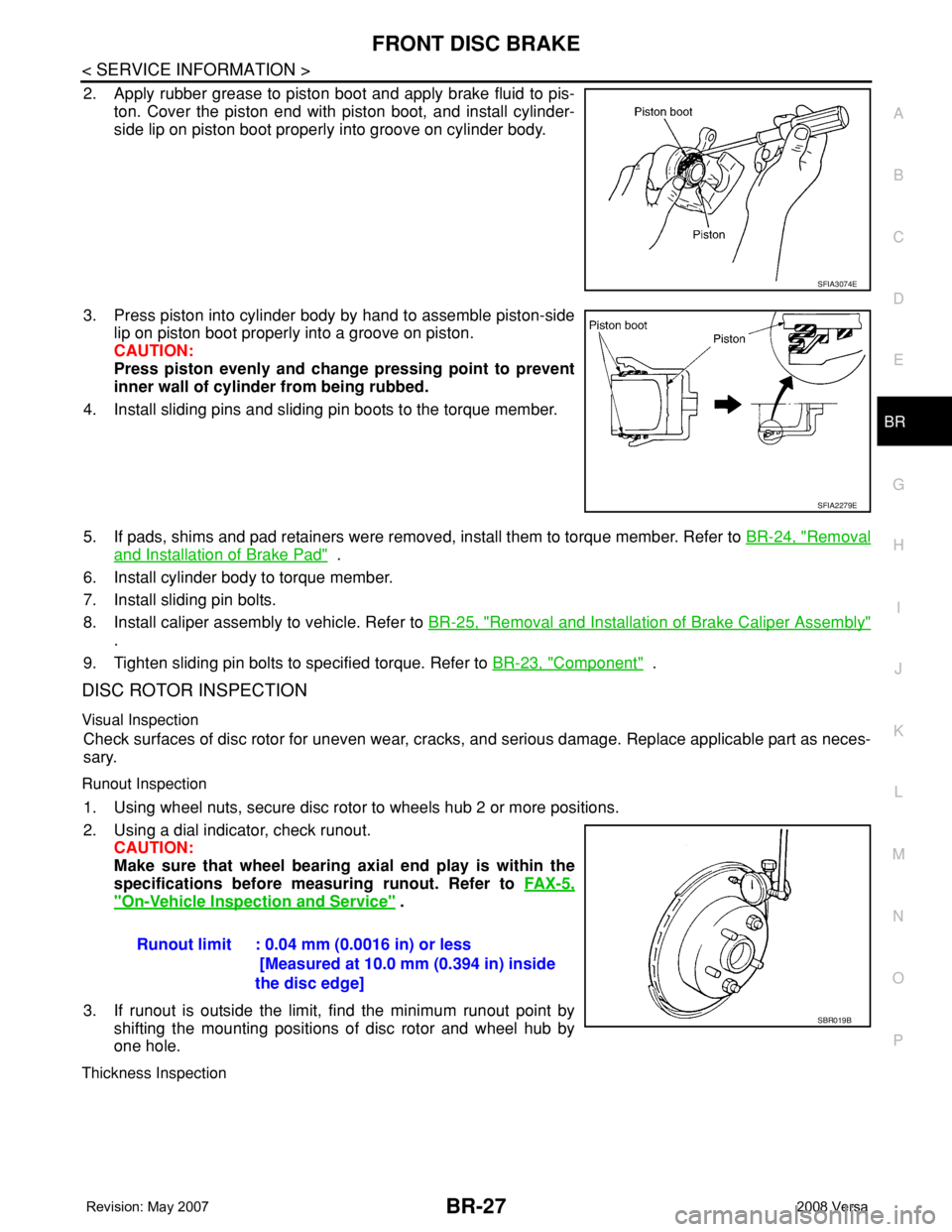
2. Apply rubber grease to piston boot and apply brake fluid to pis-
ton. Cover the piston end with piston boot, and install cylinder-
side lip on piston boot properly into groove on cylinder body.
3. Press piston into cylinder body by hand to assemble piston-side
lip on piston boot properly into a groove on piston.
CAUTION:
Press piston evenly and change pressing point to prevent
inner wall of cylinder from being rubbed.
4. Install sliding pins and sliding pin boots to the torque member.
5. If pads, shims and pad retainers were removed, install them to torque member. Refer to BR-24, "
Removal
and Installation of Brake Pad" .
6. Install cylinder body to torque member.
7. Install sliding pin bolts.
8. Install caliper assembly to vehicle. Refer to BR-25, "
Removal and Installation of Brake Caliper Assembly"
.
9. Tighten sliding pin bolts to specified torque. Refer to BR-23, "
Component" .
DISC ROTOR INSPECTION
Visual Inspection
Check surfaces of disc rotor for uneven wear, cracks, and serious damage. Replace applicable part as neces-
sary.
Runout Inspection
1. Using wheel nuts, secure disc rotor to wheels hub 2 or more positions.
2. Using a dial indicator, check runout.
CAUTION:
Make sure that wheel bearing axial end play is within the
specifications before measuring runout. Refer to FA X - 5 ,
"On-Vehicle Inspection and Service" .
3. If runout is outside the limit, find the minimum runout point by
shifting the mounting positions of disc rotor and wheel hub by
one hole.
Thickness Inspection
SFIA3074E
SFIA2279E
Runout limit : 0.04 mm (0.0016 in) or less
[Measured at 10.0 mm (0.394 in) inside
the disc edge]
SBR019B
Page 763 of 2771
BR-32
< SERVICE INFORMATION >
REAR DRUM BRAKE
5. Connect the parking brake rear cable to the operating lever.
6. Install the shoe assembly. After assembly, be sure that each part is installed properly.
CAUTION:
Do not damage the wheel cylinder piston boot.
7. Install the brake drum.
8. Depress brake pedal for several times (approximately 2, 3 times).
9. Adjust clearance of brake shoe. Refer to PB-4, "
On-Vehicle Service" .
10. Install tires to the vehicle.
Removal and Installation of Wheel CylinderINFOID:0000000001703804
REMOVAL
1. Drain brake fluid. Refer to BR-8, "Drain and Refill" .
2. Remove the rear brake shoe assembly. Refer to BR-29, "
Removal and Installation of Drum Brake Assem-
bly" .
3. Remove the brake tube from the wheel cylinder.
4. Remove bolts on the wheel cylinder, and then remove wheel cylinder from the back plate.
INSTALLATION
• Installation is the reverse order of removal. Tighten bolts to the specified torque. Refer to BR-29, "Compo-
nent" .
• Refill with new brake fluid and bleed air. Refer to BR-8, "
Bleeding Brake System" .
Disassembly and Assembly of Wheel CylinderINFOID:0000000001703805
DISASSEMBLY
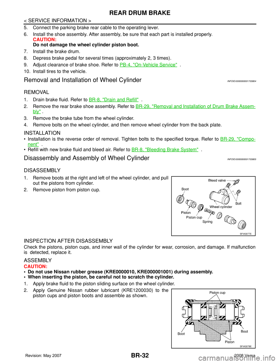
1. Remove boots at the right and left of the wheel cylinder, and pull
out the pistons from cylinder.
2. Remove piston from piston cup.
INSPECTION AFTER DISASSEMBLY
Check the pistons, piston cups, and inner wall of the cylinder for wear, corrosion, and damage. If malfunction
is detected, replace it.
ASSEMBLY
CAUTION:
• Do not use Nissan rubber grease (KRE0000010, KRE000001001) during assembly.
• When inserting the piston, be careful not to scratch the cylinder.
1. Apply brake fluid to the piston sliding surface on the wheel cylinder.
2. Apply Genuine Nissan rubber lubricant (KRE1200030) to the
piston cups and piston boots and assemble as shown.
SFIA3077E
SFIA3078E
Page 769 of 2771
![NISSAN TIIDA 2008 Service Repair Manual BRC-4
< SERVICE INFORMATION >[ABS]
PREPARATION
PREPARATION
Special Service ToolINFOID:0000000001703823
The actual shapes of Kent-Moore tools may differ from those of special service tools illustrated NISSAN TIIDA 2008 Service Repair Manual BRC-4
< SERVICE INFORMATION >[ABS]
PREPARATION
PREPARATION
Special Service ToolINFOID:0000000001703823
The actual shapes of Kent-Moore tools may differ from those of special service tools illustrated](/img/5/57399/w960_57399-768.png)
BRC-4
< SERVICE INFORMATION >[ABS]
PREPARATION
PREPARATION
Special Service ToolINFOID:0000000001703823
The actual shapes of Kent-Moore tools may differ from those of special service tools illustrated here.
Commercial Service ToolINFOID:0000000001703824
Tool number
(Kent-Moore No.)
Tool nameDescription
KV991J0080
(J-45741)
ABS active wheel sensor testerChecking operation of ABS active wheel sen-
sors
WFIA0101E
Tool nameDescription
1. Flare nut crowfoot
2. Torque wrenchRemoving and installing brake piping
a: 10 mm (0.39 in)/12 mm (0.47 in)
S-NT360
Page 797 of 2771
![NISSAN TIIDA 2008 Service Repair Manual BRC-32
< SERVICE INFORMATION >[ABS]
WHEEL SENSORS
WHEEL SENSORS
Removal and InstallationINFOID:0000000001703850
NOTE:
The top portion of the figure (front side) shows view from LH side of vehicle. RH NISSAN TIIDA 2008 Service Repair Manual BRC-32
< SERVICE INFORMATION >[ABS]
WHEEL SENSORS
WHEEL SENSORS
Removal and InstallationINFOID:0000000001703850
NOTE:
The top portion of the figure (front side) shows view from LH side of vehicle. RH](/img/5/57399/w960_57399-796.png)
BRC-32
< SERVICE INFORMATION >[ABS]
WHEEL SENSORS
WHEEL SENSORS
Removal and InstallationINFOID:0000000001703850
NOTE:
The top portion of the figure (front side) shows view from LH side of vehicle. RH side is the mirror image.
REMOVAL
Pay attention to the following when removing wheel sensor.
CAUTION:
• As much as possible, avoid rotating wheel sensor when removing it. Pull wheel sensors out without
pulling on sensor harness.
• Take care to avoid damaging wheel sensor edges or rotor teeth. Remove wheel sensor first before
removing front or rear wheel hub. This is to avoid damage to wheel sensor wiring and loss of sensor
function.
INSTALLATION
Pay attention to the following when installing wheel sensor. Tighten installation bolts and nuts to the specified
torques.
• When installing, make sure there is no foreign material such as iron chips on and in the mounting hole of the
wheel sensor. Make sure no foreign material has been caught in the sensor rotor. Remove any foreign mate-
rial and clean the mount.
• When installing front wheel sensor, press rubber grommets of strut bracket and body all the way in until they
get locked, and be careful not to apply a twist to harness. Harness should not be twisted after installation.
(Install it with harness paint mark on body side grommet facing front of vehicle, and the strut side grommet
facing outside of vehicle.)
A. Front B. Rear 1. Front wheel sensor connector (LH)
2. Front wheel sensor (LH) 3. Rear wheel sensor (LH) 4. Rear wheel sensor connector (LH)
5. Rear wheel sensor connector (RH) 6. Rear wheel sensor (RH) 7. Side member
8. Left 9. Right : Front
Refer to GI section for symbol marks in the figure.
SFIA3090E
Page 1221 of 2771
DTC P0011 IVT CONTROL
EC-147
< SERVICE INFORMATION >
C
D
E
F
G
H
I
J
K
L
MA
EC
N
P O
DTC P0011 IVT CONTROL
DescriptionINFOID:0000000001702617
SYSTEM DESCRIPTION
*: This signal is sent to the ECM through CAN communication line.
This mechanism hydraulically controls cam phases continuously with the fixed operating angle of the intake
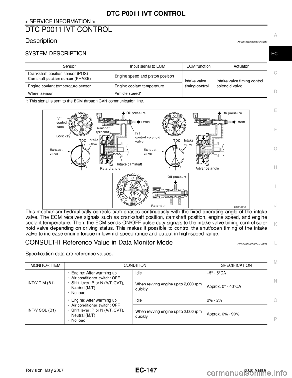
valve. The ECM receives signals such as crankshaft position, camshaft position, engine speed, and engine
coolant temperature. Then, the ECM sends ON/OFF pulse duty signals to the intake valve timing control sole-
noid valve depending on driving status. This makes it possible to control the shut/open timing of the intake
valve to increase engine torque in low/mid speed range and output in high-speed range.
CONSULT-II Reference Value in Data Monitor ModeINFOID:0000000001702618
Specification data are reference values.
Sensor Input signal to ECM ECM function Actuator
Crankshaft position sensor (POS)
Camshaft position sensor (PHASE)Engine speed and piston position
Intake valve
timing controlIntake valve timing control
solenoid valve Engine coolant temperature sensor Engine coolant temperature
Wheel sensor Vehicle speed*
PBIB3333E
MONITOR ITEM CONDITION SPECIFICATION
INT/V TIM (B1)• Engine: After warming up
• Air conditioner switch: OFF
• Shift lever: P or N (A/T, CVT),
Neutral (M/T)
•No loadIdle−5° - 5°CA
When revving engine up to 2,000 rpm
quicklyApprox. 0° - 40°CA
INT/V SOL (B1)• Engine: After warming up
• Air conditioner switch: OFF
• Shift lever: P or N (A/T, CVT),
Neutral (M/T)
•No loadIdle 0% - 2%
When revving engine up to 2,000 rpm
quicklyApprox. 0% - 90%
Page 1681 of 2771

EM-4
< SERVICE INFORMATION >
PRECAUTIONS
2. Use the Intelligent Key or mechanical key to turn the ignition switch to the ″ACC″ position. At this time, the
steering lock will be released.
3. Disconnect both battery cables. The steering lock will remain released and the steering wheel can be
rotated.
4. Perform the necessary repair operation.
5. When the repair work is completed, return the ignition switch to the ″LOCK″ position before connecting
the battery cables. (At this time, the steering lock mechanism will engage.)
6. Perform a self-diagnosis check of all control units using CONSULT-III.
Precaution for Drain CoolantINFOID:0000000001702463
• Drain coolant when engine is cooled.
Precaution for Disconnecting Fuel PipingINFOID:0000000001702464
• Before starting work, make sure no fire or spark producing items are in the work area.
• Release fuel pressure before disassembly.
• After disconnecting pipes, plug openings to stop fuel leakage.
Precaution for Removal and DisassemblyINFOID:0000000001702465
• When instructed to use special service tools, use the specified tools. Always be careful to work safely, avoid
forceful or uninstructed operations.
• Exercise maximum care to avoid damage to mating or sliding surfaces.
• Cover openings of engine system with tape or the equivalent, if necessary, to seal out foreign materials.
• Mark and arrange disassembly parts in an organized way for easy troubleshooting and assembly.
• When loosening nuts and bolts, as a basic rule, start with the one furthest outside, then the one diagonally
opposite, and so on. If the order of loosening is specified, do exactly as specified. Power tools may be used
where noted in the step.
Precaution for Inspection, Repair and ReplacementINFOID:0000000001702466
• Before repairing or replacing, thoroughly inspect parts. Inspect new replacement parts in the same way, and
replace if necessary.
Precaution for Assembly and InstallationINFOID:0000000001702467
• Use torque wrench to tighten bolts or nuts to specification.
• When tightening nuts and bolts, as a basic rule, equally tighten in several different steps starting with the
ones in center, then ones on inside and outside diagonally in this order. If the order of tightening is specified,
do exactly as specified.
• Replace with new gasket, packing, oil seal or O-ring.
• Thoroughly wash, clean, and air-blow each part. Carefully check oil or coolant passages for any restriction
and blockage.
• Avoid damaging sliding or mating surfaces. Completely remove foreign materials such as cloth lint or dust.
Before assembly, oil sliding surfaces well.
• Release air within route after draining coolant.
• Before starting engine, apply fuel pressure to fuel lines with turning ignition switch ON (with engine stopped).
Then make sure that there are no leaks at fuel line connections.
• After repairing, start engine and increase engine speed to check coolant, fuel, oil, and exhaust systems for
leakage.
Parts Requiring Angular TighteningINFOID:0000000001702468
• Use an angle wrench for the final tightening of the following engine parts:
- Cylinder head bolts
- Camshaft sprocket (INT)
- Main bearing cap bolts
- Connecting rod cap nuts
- Crankshaft pulley bolt (No angle wrench is required as the bolt flange is provided with notches for angular
tightening)