coolant temperature NISSAN TIIDA 2009 Service Owners Manual
[x] Cancel search | Manufacturer: NISSAN, Model Year: 2009, Model line: TIIDA, Model: NISSAN TIIDA 2009Pages: 4331, PDF Size: 58.04 MB
Page 2242 of 4331
![NISSAN TIIDA 2009 Service Owners Manual EC-886< SERVICE INFOMATION >
[MR TYPE 1]
DTC P1217 ENGINE
OVER TEMPERATURE
DTC P1217 ENGINE OVER TEMPERATURE
System Description INFOID:0000000004537393
SYSTEM DESCRIPTION
NOTE:
• If DTC P1217 is](/img/5/57398/w960_57398-2241.png "NISSAN TIIDA 2009 Service Owners Manual EC-886< SERVICE INFOMATION >
[MR TYPE 1]
DTC P1217 ENGINE
OVER TEMPERATURE
DTC P1217 ENGINE OVER TEMPERATURE
System Description INFOID:0000000004537393
SYSTEM DESCRIPTION
NOTE:
• If DTC P1217 is")
EC-886< SERVICE INFOMATION >
[MR TYPE 1]
DTC P1217 ENGINE
OVER TEMPERATURE
DTC P1217 ENGINE OVER TEMPERATURE
System Description INFOID:0000000004537393
SYSTEM DESCRIPTION
NOTE:
• If DTC P1217 is displayed with DTC U1000 or U1001, first perform the trouble diagnosis for DTC
U1000, U1001. Refer to EC-633 .
• If DTC P1217 is displayed with DTC U1010, first pe rform the trouble diagnosis for DTC U1010. Refer
to EC-635 .
Cooling Fan Control
*1: The ECM determines the start signal status by the signals of engine speed and battery voltage.
*2: This signal is sent to ECM through CAN communication line.
The ECM controls the cooling fan corresponding to the vehicle speed, engine coolant temperature, refrigerant
pressure, and air conditioner ON signal. The contro l system has 3-step control [HIGH/LOW/OFF].
Cooling Fan Operation
Models with A/C
Models without A/C Sensor Input Signal to ECM ECM function Actuator
Crankshaft position sensor (POS)
Camshaft position sensor (PHASE) Engine speed*
1
Cooling fan
control IPDM E/R
(Cooling fan relays)
Battery
Battery voltage*1
ABS actuator and electric unit (control unit)
Vehicle speed*2
Combination meter
Engine coolant temperature sensor Engine coolant temperature
Air conditioner switch Air conditioner ON signal*2
Refrigerant pressure sensor Refrigerant pressure PBIB2483E
PBIB3335E
Page 2243 of 4331
EC
NP
O
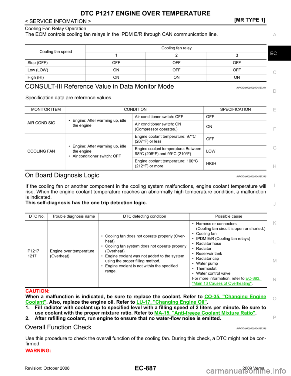
Cooling Fan Relay Operation
The ECM controls cooling fan relays in the IPDM E/R through CAN communication line.
CONSULT-III Reference Val ue in Data Monitor Mode INFOID:0000000004537394
Specification data are reference values.
On Board Diagnosis Logic INFOID:0000000004537395
If the cooling fan or another component in the cooli ng system malfunctions, engine coolant temperature will
rise. When the engine coolant temperature reaches an abnormally high temperature condition, a malfunction
is indicated.
This self-diagnosis has the on e trip detection logic.
CAUTION:
When a malfunction is in dicated, be sure to replace the coolant. Refer to CO-35, " Changing Engine
Coolant " . Also, replace the engine oil. Refer to
LU-17, " Changing Engine Oil " .
1. Fill radiator with coolant up to specified level with a filling speed of 2 liters per minute. Be sure to
use coolant with the proper mixture ratio. Refer to MA-15, " Anti-freeze Coolant Mixture Ratio " .
2. After refilling coolant, run engine to ensure that no water-flow noise is emitted.
Overall Function Check INFOID:0000000004537396
Use this procedure to check the overall function of the cooling fan. During this check, a DTC might not be con-
firmed.
WARNING: Cooling fan speed
Cooling fan relay
1 2 3
Stop (OFF) OFF OFF OFF
Low (LOW) ON OFF OFF
High (HI) ON ON ON MONITOR ITEM CONDITION SPECIFICATION
AIR COND SIG • Engine: After warming up, idle
the engine Air conditioner switch: OFF OFF
Air conditioner switch: ON
(Compressor operates.) ON
COOLING FAN • Engine: After warming up, idle
the engine
• Air conditioner switch: OFF Engine coolant temperature: 97
°C
(207 °F) or less OFF
Engine coolant temperature: Between
98 °C (208 °F) and 99 °C (210 °F) LOW
Engine coolant temperature: 100 °C
(212 °F) or more HIGHDTC No. Trouble diagnosis name DTC detecting condition Possible cause
P1217
1217 Engine over temperature
(Overheat) • Cooling fan does not operate properly (Over-
heat).
• Cooling fan system does not operate properly (Overheat).
• Engine coolant was not added to the system using the proper filling method.
• Engine coolant is not within the specified
range. • Harness or connectors
(Cooling fan circuit is open or shorted.)
• Cooling fan
• IPDM E/R (Cooling fan relays)
• Radiator hose
• Radiator
• Reservoir tank
• Radiator cap
• Water pump
• Thermostat
• Water control valve
For more information, refer to EC-893, " Main 13 Causes of Overheating " .
Page 2244 of 4331
![NISSAN TIIDA 2009 Service Owners Manual EC-888< SERVICE INFOMATION >
[MR TYPE 1]
DTC P1217 ENGINE
OVER TEMPERATURE
Never remove the radiator cap when the engine is hot. Serious burns could be caused by high pres-
sure flui](/img/5/57398/w960_57398-2243.png "NISSAN TIIDA 2009 Service Owners Manual EC-888< SERVICE INFOMATION >
[MR TYPE 1]
DTC P1217 ENGINE
OVER TEMPERATURE
Never remove the radiator cap when the engine is hot. Serious burns could be caused by high pres-
sure flui")
EC-888< SERVICE INFOMATION >
[MR TYPE 1]
DTC P1217 ENGINE
OVER TEMPERATURE
Never remove the radiator cap when the engine is hot. Serious burns could be caused by high pres-
sure fluid escaping from the reser voir tank or the radiator.
Wrap a thick cloth around cap. Carefully remove the cap by turning it a quarter turn to allow built-up
pressure to escape. Then turn the cap all the way off.
WITH CONSULT-III
1. Check the coolant level in the reservoir tank and radiator. Allow engine to cool before checking coolant level.
If the coolant level in the reservoir tank and/or radiator is below
the proper range, skip the following steps and go to EC-890," Diagnosis Procedure " or
EC-890, " Diagnosis Procedure " .
2. Confirm whether customer filled the coolant or not. If customer
filled the coolant, skip the following steps and go to EC-890," Diagnosis Procedure " or
EC-890, " Diagnosis Procedure " .
3. Turn ignition switch ON.
4. Perform “COOLING FAN” in “ACTIVE TEST” mode with CON- SULT-III.
5. If the results are NG, go to EC-890, " Diagnosis Procedure " or
EC-890, " Diagnosis Procedure " .
WITH GST
1. Check the coolant level in the reservoir tank and radiator. Allow engine to cool before checking coolant level.
If the coolant level in the reservoir tank and/or radiator is below
the proper range, skip the following steps and go to EC-890," Diagnosis Procedure " .
2. Confirm whether customer filled the coolant or not. If customer
filled the coolant, skip the following steps and go to EC-890," Diagnosis Procedure " .
3. Perform IPDM/ER auto active te st and check cooling fan motor
operation. Refer to PG-19, " Auto Active Test " .
4. If NG, go to EC-890, " Diagnosis Procedure " . SEF621W
SEF621W
Page 2247 of 4331
EC
NP
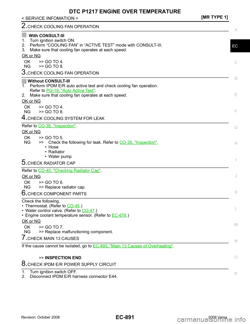
O OK >> GO TO 4.
NG >> GO TO 8. Auto Active Test " .
2. Make sure that cooling fan operates at each speed.
OK or NG OK >> GO TO 4.
NG >> GO TO 8. Inspection " .
OK or NG OK >> GO TO 5.
NG >> Check the following for leak. Refer to CO-35, " Inspection " .
• Hose
• Radiator
• Water pump Checking Radiator Cap " .
OK or NG OK >> GO TO 6.
NG >> Replace radiator cap. .)
• Water control valve. (Refer to CO-47 .)
• Engine coolant temperature sensor. (Refer to EC-678 .)
OK or NG OK >> GO TO 7.
NG >> Replace malfunctioning component. Main 13 Causes of Overheating " .
>> INSPECTION END
Page 2249 of 4331
EC
NP
O
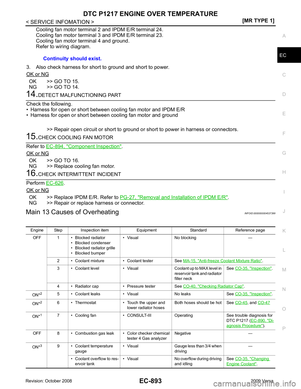
Cooling fan motor terminal 2 and IPDM E/R terminal 24.
Cooling fan motor terminal 3 and IPDM E/R terminal 23.
Cooling fan motor terminal 4 and ground.
Refer to wiring diagram.
3. Also check harness for short to ground and short to power.
OK or NG OK >> GO TO 15.
NG >> GO TO 14. Component Inspection " .
OK or NG OK >> GO TO 16.
NG >> Replace cooling fan motor. .
OK or NG OK >> Replace IPDM E/R. Refer to
PG-27, " Removal and Installation of IPDM E/R " .
NG >> Repair or replace harness or connector.
Main 13 Causes of Overheating INFOID:0000000004537399
Continuity should exist.
Engine Step Inspection item Equipment Standard Reference page OFF 1 • Blocked radiator • Blocked condenser
• Blocked radiator grille
• Blocked bumper • Visual No blocking —
2 • Coolant mixture • Coolant tester See MA-15, " Anti-freeze Coolant Mixture Ratio " .
3 • Coolant level • Visual Coolant up to MAX level in reservoir tank and radiator
filler neck See
CO-35, " Inspection " .
4 • Radiator cap • Pressure tester See CO-40, " Checking Radiator Cap " .
ON* 2
5 • Coolant leaks • Visual No leaks See CO-35, " Inspection " .
ON* 2
6 • Thermostat • Touch the upper and
lower radiator hosesBoth hoses should be hot See
CO-45 , and
CO-47 ON*
1
7 • Cooling fan • CONSULT-III Operating See trouble diagnosis for
DTC P1217 (EC-890, " Di-
agnosis Procedure " ).
OFF 8 • Combustion gas leak • Color checker chemical tester 4 Gas analyzerNegative —
ON* 3
9 • Coolant temperature
gauge • Visual Gauge less than 3/4 when
driving —
• Coolant overflow to res- ervoir tank • Visual No overflow during driving
and idling See
CO-35, " Changing
Engine Coolant " .
Page 2250 of 4331
![NISSAN TIIDA 2009 Service Owners Manual EC-894< SERVICE INFOMATION >
[MR TYPE 1]
DTC P1217 ENGINE
OVER TEMPERATURE
*1: Turn the ignition switch ON.
*2: Engine running at 3,000 rpm for 10 minutes.
*3: Drive at 90 km/h (55 MPH) for 30 minute](/img/5/57398/w960_57398-2249.png "NISSAN TIIDA 2009 Service Owners Manual EC-894< SERVICE INFOMATION >
[MR TYPE 1]
DTC P1217 ENGINE
OVER TEMPERATURE
*1: Turn the ignition switch ON.
*2: Engine running at 3,000 rpm for 10 minutes.
*3: Drive at 90 km/h (55 MPH) for 30 minute")
EC-894< SERVICE INFOMATION >
[MR TYPE 1]
DTC P1217 ENGINE
OVER TEMPERATURE
*1: Turn the ignition switch ON.
*2: Engine running at 3,000 rpm for 10 minutes.
*3: Drive at 90 km/h (55 MPH) for 30 minutes and then let idle for 10 minutes.
*4: After 60 minutes of cool down time.
For more informat ion, refer to CO-32 .
Component Inspection INFOID:0000000004537400
COOLING FAN MOTOR
Model with A/C
1. Disconnect cooling fan motor harness connectors.
2. Supply cooling fan motor terminals with battery voltage and check operation.
Cooling fan motor should operate.
If NG, replace cooling fan motor.
Models without A/C
1. Disconnect cooling fan motor harness connectors.
2. Supply cooling fan motor terminals with battery voltage and check operation.
Cooling fan motor should operate.
If NG, replace cooling fan motor. OFF*
4
10 • Coolant return from res-
ervoir tank to radiator • Visual Should be initial level in
reservoir tank See
CO-35, " Inspection " .
OFF 11 • Water control valve • Remove and inspect
the valve Within the specified value See
CO-47, " Removal
and Installation "
OFF 12 • Cylinder head • Straight gauge feeler
gauge0.1 mm (0.004 in) Maxi-
mum distortion (warping) See
EM-185 .
13 • Cylinder block and pis- tons • Visual No scuffing on cylinder
walls or piston See
EM-199 .
Engine Step Inspection item Equipment Standard Reference page Terminals
(+) (-)
Cooling fan motor 1 2 SEF888V
Speed
terminals
(+) ( −)
Cooling fan motor Low 1 4
2 3
High 1 and 2 3 and 4 SEF734W
Page 2384 of 4331
![NISSAN TIIDA 2009 Service Owners Manual EC-1028< SERVICE INFOMATION >
[MR TYPE 2]
ENGINE CONTROL SYSTEM
*1: This sensor is not used to control the engine system under normal conditions.
*2: This signal is sent to the ECM through CAN communi](/img/5/57398/w960_57398-2383.png "NISSAN TIIDA 2009 Service Owners Manual EC-1028< SERVICE INFOMATION >
[MR TYPE 2]
ENGINE CONTROL SYSTEM
*1: This sensor is not used to control the engine system under normal conditions.
*2: This signal is sent to the ECM through CAN communi")
EC-1028< SERVICE INFOMATION >
[MR TYPE 2]
ENGINE CONTROL SYSTEM
*1: This sensor is not used to control the engine system under normal conditions.
*2: This signal is sent to the ECM through CAN communication line.
*3: ECM determines the start signal status by the signals of engine speed and battery voltage.
SYSTEM DESCRIPTION
The amount of fuel injected from the fuel injector is determined by the ECM. The ECM controls the length of
time the valve remains open (injection pulse duration). T he amount of fuel injected is a program value in the
ECM memory. The program value is preset by engi ne operating conditions. These conditions are determined
by input signals (for engine speed and intake air) from t he crankshaft position sensor (POS), camshaft position
sensor (PHASE) and the ma ss air flow sensor.
VARIOUS FUEL INJECTION I NCREASE/DECREASE COMPENSATION
In addition, the amount of fuel injected is compens ated to improve engine performance under various operat-
ing conditions as listed below.
• During warm-up
• When starting the engine
• During acceleration
• Hot-engine operation
• When selector lever is changed from N to D (A/T and CVT models)
• High-load, high-speed operation
• During deceleration
• During high engine speed operation
MIXTURE RATIO FEEDBACK CONTROL (CLOSED LOOP CONTROL) Sensor Input Signal to ECM ECM function Actuator
Crankshaft position sensor (POS) Engine speed*3
Piston position
Fuel injection
& mixture ratio
control Fuel injector
Camshaft position sensor (PHASE)
Mass air flow sensor Amount of intake air
Engine coolant temperature sensor Engine coolant temperature
Air fuel ratio (A/F) sensor 1 Density of oxygen in exhaust gas
Throttle position sensor Throttle position
Accelerator pedal position sensor Accelerator pedal position
Park/neutral position (PNP) switch Gear position
Battery Battery voltage*3
Knock sensor Engine knocking condition
EPS control unit Power steering operation*2
Heated oxygen sensor 2* 1
Density of oxygen in exhaust gas
Air conditioner switch Air conditioner operation*2
ABS actuator and electric unit (control unit)
Vehicle speed*2
Combination meter PBIB3020E
Page 2385 of 4331
![NISSAN TIIDA 2009 Service Owners Manual ENGINE CONTROL SYSTEM
EC-1029
< SERVICE INFOMATION >
[MR TYPE 2] C
D E
F
G H
I
J
K L
M A EC
NP
O
The mixture ratio feedback system provides the best air/
fuel mixture ratio for drivability and emissio](/img/5/57398/w960_57398-2384.png "NISSAN TIIDA 2009 Service Owners Manual ENGINE CONTROL SYSTEM
EC-1029
< SERVICE INFOMATION >
[MR TYPE 2] C
D E
F
G H
I
J
K L
M A EC
NP
O
The mixture ratio feedback system provides the best air/
fuel mixture ratio for drivability and emissio")
ENGINE CONTROL SYSTEM
EC-1029
< SERVICE INFOMATION >
[MR TYPE 2] C
D E
F
G H
I
J
K L
M A EC
NP
O
The mixture ratio feedback system provides the best air/
fuel mixture ratio for drivability and emission control.
The three way catalyst (manifold) can then better r educe CO, HC and NOx emissions. This system uses air
fuel ratio (A/F) sensor 1 in the exhaust manifold to monitor whether the engine operation is rich or lean. The
ECM adjusts the injection pulse width according to the sensor voltage signal. For more information about air
fuel ratio (A/F) sensor 1, refer to EC-1210 . This maintains the mixture ratio within the range of stoichiometric
(ideal air/fuel mixture).
This stage is referred to as the closed loop control condition.
Heated oxygen sensor 2 is located downstream of the th ree way catalyst (manifold). Even if the switching
characteristics of air fuel ratio (A/F) sensor 1 shift, the air/fuel ratio is controlled to stoichiometric by the signal
from heated oxygen sensor 2.
Open Loop Control The open loop system condition refers to when the ECM detects any of the following conditions. Feedback
control stops in order to maintain stabilized fuel combustion.
• Deceleration and acceleration
• High-load, high-speed operation
• Malfunction of air fuel ratio (A/F) sensor 1 or its circuit
• Insufficient activation of air fuel ratio (A /F) sensor 1 at low engine coolant temperature
• High engine coolant temperature
• During warm-up
• After shifting from N to D (A/T and CVT models)
• When starting the engine
MIXTURE RATIO SELF-LEARNING CONTROL The mixture ratio feedback control system monitors the mixture ratio signal transmitted from air fuel ratio (A/F)
sensor 1. This feedback signal is then sent to the ECM. The ECM controls the basic mixture ratio as close to
the theoretical mixture ratio as possible. However, the bas ic mixture ratio is not necessarily controlled as orig-
inally designed. Both manufacturing differences (i.e., mass air flow sensor hot wire) and characteristic
changes during operation (i.e., fuel injector clogging) directly affect mixture ratio.
Accordingly, the difference between the basic and theoretical mixture ratios is monitored in this system. This is
then computed in terms of “injection pulse duration” to automatically compensate for the difference between
the two ratios.
“Fuel trim” refers to the feedback compensation value co mpared against the basic injection duration. Fuel trim
includes short term fuel trim and long term fuel trim.
“Short term fuel trim” is the short-term fuel compensati on used to maintain the mixture ratio at its theoretical
value. The signal from air fuel ratio (A/F) sensor 1 i ndicates whether the mixture ratio is RICH or LEAN com-
pared to the theoretical value. The signal then triggers a r eduction in fuel volume if the mixture ratio is rich, and
an increase in fuel volume if it is lean.
“Long term fuel trim” is overall fuel compensation ca rried out long-term to compensate for continual deviation
of the short term fuel trim from the central value. Such deviation will occur due to individual engine differences,
wear over time and changes in the usage environment.
FUEL INJECTION TIMING
Two types of systems are used.
Sequential Multiport Fuel Injection System
Fuel is injected into each cylinder during each engine cycl e according to the firing order. This system is used
when the engine is running.
Simultaneous Multiport Fuel Injection System Fuel is injected simultaneously into all four cylinders twice each engine cycle. In other words, pulse signals of
the same width are simultaneously transmitted from the ECM.
The four fuel injectors will then receive the signals two times for each engine cycle. SEF337W
Page 2386 of 4331

Sensor Input Signal to ECM ECM function Actuator
Park/neutral position (P NP) switch Neutral position
Fuel cut control Fuel injector
Accelerator pedal position sensor Accelerator pedal position
Engine coolant temperature sensor Engine coolant temperature
Crankshaft position sensor (POS)
Camshaft position sensor (PHASE) Engine speed
ABS actuator and electric unit (control unit) Vehicle speed*
Combination meter
Page 2389 of 4331

EC
NP
O
AUTOMATIC SPEED CONTROL DEVICE (ASCD)
System Description INFOID:0000000004499911
INPUT/OUTPUT SIGNAL CHART
*: This signal is sent to the ECM through CAN communication line.
BASIC ASCD SYSTEM Refer to Owner's Manual for ASCD operating instructions.
Automatic Speed Control Device (ASCD) allows a driver to keep vehicle at predetermined constant speed
without depressing accelerator pedal. Driver can set vehicle speed in advance between approximately 40 km/
h (25 MPH) and 144 km/h (89 MPH).
ECM controls throttle angle of electric thro ttle control actuator to regulate engine speed.
Operation status of ASCD is indicated by CRUISE i ndicator and SET indicator in combination meter. If any
malfunction occurs in ASCD system, it automatically deactivates control.
NOTE:
Always drive vehicle in safe manner according to traffic conditions and obey all traffic laws.
SET OPERATION Press MAIN switch. (The CRUISE indicato r in combination meter illuminates.)
When vehicle speed reaches a desired speed between appr oximately 40 km/h (25 MPH) and 144 km/h (89
MPH), press SET/COAST switch. (Then SET indi cator in combination meter illuminates.)
ACCELERATE OPERATION If the RESUME/ACCELERATE switch is depressed during cruise control driving, increase the vehicle speed
until the switch is released or vehicle speed reaches maximum speed controlled by the system.
And then ASCD will keep the new set speed.
CANCEL OPERATION When any of following conditions exis t, cruise operation will be canceled.
• CANCEL switch is pressed
• More than two switches at ASCD steering switch are pressed at the same time (Set speed will be cleared)
• Brake pedal is depressed
• Clutch pedal is depressed or gear position is changed to the neutral position (M/T models)
• Selector lever is changed to N, P, R position (A/T and CVT models)
• Vehicle speed decreased to 13 km/h (8 MPH) lower than the set speed
When the ECM detects any of the following conditions, the ECM will cancel the cruise operation and inform
the driver by blinking indicator lamp.
• Engine coolant temperature is slightly higher than the normal operating temperature, CRUISE lamp may
blink slowly.
When the engine coolant temperature decreases to t he normal operating temperature, CRUISE lamp will
stop blinking and the cruise operation will be able to work by pressing SET/COAST switch or RESUME/
ACCELERATE switch.
• Malfunction for some self-diagnoses regarding ASCD control: SET lamp will blink quickly.
If MAIN switch is turned to OFF during ASCD is activated, all of ASCD operations will be canceled and vehicle
speed memory will be erased.
COAST OPERATION Sensor Input signal to ECM ECM function Actuator
ASCD brake switch Brake pedal operation
ASCD vehicle speed controlElectric throttle control
actuator
Stop lamp switch Brake pedal operation
ASCD clutch switch (M/T models) Clutch pedal operation
ASCD steering switch ASCD steering switch operation
Park/neutral position (PNP) switch Gear position
ABS actuator and electric unit (con-
trol unit) Vehicle speed*
Combination meter
TCM Powertrain revolution*