coolant temperature NISSAN TIIDA 2009 Service Manual PDF
[x] Cancel search | Manufacturer: NISSAN, Model Year: 2009, Model line: TIIDA, Model: NISSAN TIIDA 2009Pages: 4331, PDF Size: 58.04 MB
Page 1879 of 4331

EC
NP
O
AIR CONDITIONING
CUT CONTROL
Input/Output Signal Chart INFOID:0000000004537023
*1: This signal is sent to the ECM through CAN communication line.
*2: ECM determines the start signal status by the signals of engine speed and battery voltage.
System Description INFOID:0000000004537024
This system improves engine operation when the air conditioner is used.
Under the following conditions, the air conditioner is turned off.
• When the accelerator pedal is fully depressed.
• When cranking the engine.
• At high engine speeds.
• When the engine coolant temperature becomes excessively high.
• When operating power steering during low engine speed or low vehicle speed.
• When engine speed is excessively low.
• When refrigerant pressure is excessively low or high. Sensor Input Signal to ECM ECM function Actuator
Air conditioner switch Air conditioner ON signal*1
Air conditioner
cut control Air conditioner relay
Accelerator pedal position sensor Accelerator pedal position
Crankshaft position sensor (POS)
Camshaft position sensor (PHASE) Engine speed*
2
Engine coolant temperature sensor Engine coolant temperature
Battery Battery voltage*2
Refrigerant pressure sensor Refrigerant pressure
EPS control unit Power steering operation*1
ABS actuator and electric unit (control unit) Vehicle speed*1
Combination meter
Page 1907 of 4331
![NISSAN TIIDA 2009 Service Manual PDF ON BOARD DIAGNOSTIC (OBD) SYSTEM
EC-551
< SERVICE INFOMATION >
[MR TYPE 1] C
D E
F
G H
I
J
K L
M A EC
NP
O
• Sea level
• Flat road
• Ambient air temperature: 20 - 30 °C (68 - 86 °F)
• Diagno](/img/5/57398/w960_57398-1906.png "NISSAN TIIDA 2009 Service Manual PDF ON BOARD DIAGNOSTIC (OBD) SYSTEM
EC-551
< SERVICE INFOMATION >
[MR TYPE 1] C
D E
F
G H
I
J
K L
M A EC
NP
O
• Sea level
• Flat road
• Ambient air temperature: 20 - 30 °C (68 - 86 °F)
• Diagno")
ON BOARD DIAGNOSTIC (OBD) SYSTEM
EC-551
< SERVICE INFOMATION >
[MR TYPE 1] C
D E
F
G H
I
J
K L
M A EC
NP
O
• Sea level
• Flat road
• Ambient air temperature: 20 - 30 °C (68 - 86 °F)
• Diagnosis is performed as quickly as possible under normal conditions.
Under different conditions [For example: ambient air temperature other than 20 - 30 °C (68 - 86 °F)], diagno-
sis may also be performed.
Pattern 1:
• The engine is started at the engine coolant temperature of −10 to 35 °C (14 to 95 °F)
(where the voltage between the ECM terminal 38 and ground is 3.0 - 4.3V).
• The engine must be operated at idle speed until the engine coolant temperature is greater than 70 °C
(158 °F) (where the voltage between the ECM te rminal 38 and ground is lower than 1.4V).
• The engine is started at the fuel tank temperature of warmer than 0 °C (32 °F) (where the voltage
between the ECM terminal 43 and ground is less than 4.1V).
Pattern 2:
• When steady-state driving is performed again even afte r it is interrupted, each diagnosis can be conducted.
In this case, the time required for diagnosis may be extended.
Pattern 3:
• Operate vehicle following the driving pattern shown in the figure.
• Release the accelerator pedal during decelerating vehicle speed
from 90 km/h (56 MPH) to 0 km/h (0 MPH).
Pattern 4:
• The accelerator pedal must be held very steady during steady-
state driving.
• If the accelerator pedal is moved, the test must be conducted all over again.
*1: Depress the accelerator pedal until vehicle speed is 90 km/h (56
MPH), then release the accelerator pedal and keep it released for
more than 10 seconds. Depress the accelerator pedal until vehicle
speed is 90 km/h (56 MPH) again.
*2: Checking the vehicle speed with GST is advised.
Suggested Transmission Gear Po sition for A/T and CVT Models
Set the selector lever in the D position (CVT), D position with the overdrive switch turned ON (A/T).
Suggested upshift speeds for M/T models
Shown below are suggested vehicle speeds for shifting into a higher gear. These suggestions relate to fuel
economy and vehicle performance. Actual upshift speeds will vary according to road conditions, the weather
and individual driving habits.
Suggested Maximum Speed in Each Gear
Downshift to a lower gear if the engine is not running smoothly, or if you need to accelerate.
Do not exceed the maximum suggested speed (shown below) in any gear. For level road driving, use the high-
est gear suggested for that speed. Always observe post ed speed limits and drive according to the road condi-
tions to ensure safe operation. Do not over-rev t he engine when shifting to a lower gear as it may cause
engine damage or loss of vehicle control. PBIB2244E
For normal accelera
tion in low alti-
tude areas
[less than 1,219 m (4,000 ft)]: For quick acceleration in low alti-
tude areas For high attitude areas
[over 1,219m (4,000 ft)]:
Gear change ACCEL shift point km/h (MPH) km/h (MPH) km/h (MPH)
1st to 2nd 13 (8) 24 (15) 24 (15)
2nd to 3rd 27 (17) 40 (25) 40 (25)
3rd to 4th 40 (25) 53 (33) 65 (40)
4th to 5th 58 (36) 71 (44) 73 (45)
5th to 6th 82 (51) 82 (51) 82 (51)
Page 1919 of 4331

EC
NP
O
All components and systems should be monitored at least once by the OBD system.
• The B counter will be cleared when the malfunction is detected once regardless of the driving pattern.
• The B counter will be counted up when driving pattern B is satisfied without any malfunction.
• The MIL will go off when the B counter reaches 3. (*2 in “OBD SYSTEM OPERATION CHART”)
The following conditions should be satisfied at the same time:
Engine speed: (Engine speed in the freeze frame data) ±375 rpm
Calculated load value: (Calculated load value in the freeze frame data) x (1 ±0.1) [%]
Engine coolant temperature (T) condition:
• When the freeze frame data shows lower than 70 °C (158 °F), “T” should be lower than 70 °C (158 °F).
• When the freeze frame data shows higher than or equal to 70 °C (158 °F), “T” should be higher than or equal
to 70 °C (158 °F).
Example:
If the stored freeze frame data is as follows:
Engine speed: 850 rpm, Calculated load val ue: 30%, Engine coolant temperature: 80°C (176 °F)
To be satisfied with driving pattern C, the v ehicle should run under the following conditions:
Engine speed: 475 - 1,225 rpm, Calculated load value: 27 - 33%, Engine coolant temperature: more than 70°C
(158 °F)
• The C counter will be cleared when the malfunction is detected regardless of vehicle conditions above.
• The C counter will be counted up when vehicle conditions above is satisfied without the same malfunction.
• The DTC will not be displayed after C counter reaches 80.
• The 1st trip DTC will be cleared when C counter is counted once without the same malfunction after DTC is
stored in ECM.
RELATIONSHIP BETWEEN MIL, DTC, 1ST TRIP DTC AND DRIVING PATTERNS EXCEPT FOR
“MISFIRE
Page 1922 of 4331
![NISSAN TIIDA 2009 Service Manual PDF EC-566< SERVICE INFOMATION >
[MR TYPE 1]
BASIC SERVICE PROCEDURE
BASIC SERVICE PROCEDURE
Basic Inspection INFOID:00000000045370431.
INSPECTION START
1. Check service records for any recent repairs tha](/img/5/57398/w960_57398-1921.png "NISSAN TIIDA 2009 Service Manual PDF EC-566< SERVICE INFOMATION >
[MR TYPE 1]
BASIC SERVICE PROCEDURE
BASIC SERVICE PROCEDURE
Basic Inspection INFOID:00000000045370431.
INSPECTION START
1. Check service records for any recent repairs tha")
EC-566< SERVICE INFOMATION >
[MR TYPE 1]
BASIC SERVICE PROCEDURE
BASIC SERVICE PROCEDURE
Basic Inspection INFOID:00000000045370431.
INSPECTION START
1. Check service records for any recent repairs that ma y indicate a related malfunction, or a current need for
scheduled maintenance.
2. Open engine hood and check the following:
- Harness connectors for improper connections
- Wiring harness for improper connections, pinches and cut
- Vacuum hoses for splits, kinks and improper connections
- Hoses and ducts for leaks
- Air cleaner clogging
- Gasket
3. Confirm that electrical or mechanical loads are not applied.
- Headlamp switch is OFF.
- Air conditioner switch is OFF.
- Rear window defogger switch is OFF.
- Steering wheel is in the straight-ahead position, etc.
4. Start engine and warm it up until engine coolant temperature indicator points the middle of gauge.
Ensure engine stays below 1,000 rpm.
5. Run engine at about 2,000 rpm for about 2 minutes under no load.
6. Make sure that no DTC is displayed with CONSULT-III or GST.
OK or NG OK >> GO TO 3.
NG >> GO TO 2. 2.
REPAIR OR REPLACE
Repair or replace components as necessary according to corresponding Diagnostic Procedure.
>> GO TO 3. 3.
CHECK TARGET IDLE SPEED
With CONSULT-III
1. Run engine at about 2,000 rpm for about 2 minutes under no load. SEF983U
SEF976U
SEF977U
Page 1928 of 4331

Idle Air Volume Learning " .
VIN Registration INFOID:0000000004537046
DESCRIPTION
VIN Registration is an operation to registering VIN in ECM. It must be performed each time ECM is replaced.
NOTE:
Accurate VIN which is registered in ECM ma y be required for Inspection & Maintenance (I/M).
OPERATION PROCEDURE
With CONSULT-III
1. Check the VIN of the vehicle and note it. Refer to GI-43 .
2. Turn ignition switch ON and engine stopped.
3. Select “VIN REGISTRATION ” in “WORK SUPPORT” mode.
4. Follow the instruction of CONSULT-III display.
Accelerator Pedal Released Position Learning INFOID:0000000004537047
DESCRIPTION
Accelerator Pedal Released Position Learning is an operati on to learn the fully released position of the accel-
erator pedal by monitoring the accelerator pedal positi on sensor output signal. It must be performed each time
harness connector of accelerator pedal pos ition sensor or ECM is disconnected.
OPERATION PROCEDURE
1. Make sure that accelerator pedal is fully released.
2. Turn ignition switch ON and wait at least 2 seconds.
3. Turn ignition switch OFF and wait at least 10 seconds.
4. Turn ignition switch ON and wait at least 2 seconds.
5. Turn ignition switch OFF and wait at least 10 seconds.
Throttle Valve Clos ed Position Learning INFOID:0000000004537048
DESCRIPTION
Throttle Valve Closed Position Learning is an operation to l earn the fully closed position of the throttle valve by
monitoring the throttle position sensor output signal . It must be performed each time harness connector of
electric throttle control actuator or ECM is disconnected.
OPERATION PROCEDURE
1. Make sure that accelerator pedal is fully released.
2. Turn ignition switch ON.
3. Turn ignition switch OFF and wait at least 10 seconds. Make sure that throttle valve moves during above 10 seconds by confirming the operating sound.
Idle Air Volume Learning INFOID:0000000004537049
DESCRIPTION
Idle Air Volume Learning is an operation to learn the idle air volume that keeps each engine within the specific
range. It must be performed under any of the following conditions:
• Each time electric throttle control actuator or ECM is replaced.
• Idle speed or ignition timing is out of specification.
PREPARATION
Before performing Idle Air Volume Learning, make sure that all of the following conditions are satisfied.
Learning will be cancelled if any of the follo wing conditions are missed for even a moment.
• Battery voltage: More than 12.9V (At idle)
• Engine coolant temperature: 70 - 95 °C (158 - 203 °F)
• Park/neutral position (PNP) switch: ON
• Electric load switch: OFF
Page 1939 of 4331

EC
NP
O
• When there is an open circuit on MIL circuit, the ECM c
annot warn the driver by lighting up MIL when there
is malfunction on engine control system.
Therefore, when electrical controlled throttle and pa rt of ECM related diagnoses are continuously detected
as NG for 5 trips, ECM warns the driver that engine control system malfunctions and MIL circuit is open by
means of operating fail-safe function.
The fail-safe function also operates when above diagnos es except MIL circuit are detected and demands the
driver to repair the malfunction.
Symptom Matrix Chart INFOID:0000000004537054
SYSTEM — BASIC ENGINE CONTROL SYSTEM P0117
P0118 Engine coolant temperature
sensor circuit Engine coolant temperature will be determined by ECM based on the following condi-
tion.
CONSULT-III displays the engine coolant temperature decided by ECM.
Condition Engine coolant temperature decided
(CONSULT-III display)
Just as ignition switch is turned ON
or START 40
°C (104 °F)
Approx. 4 minutes or more after
engine sarting. 80
°C (176 °F)
Except as shown above 40 - 80
°C (104 - 176 °F)
(Depends on the time)
When the fail-safe system for engine coolant temperature sensor is activated, the cool-
ing fan operates while engine is running.
P0122
P0123
P0222
P0223
P2135 Throttle position sensor The ECM controls the electric throttle control actuator in regulating the throttle opening
in order for the idle position to be within +10 degrees.
The ECM regulates the opening speed of the throttle valve to be slower than the normal
condition.
So, the acceleration will be poor.
P0643 Sensor power supply ECM stops the electric throttle control actuator control, throttle valve is maintained at a fixed opening (approx. 5 degrees) by the return spring.
P2100
P2103 Throttle control relay ECM stops the electric throttle control actuator control, throttle valve is maintained at a
fixed opening (approx. 5 degrees) by the return spring.
P2101 Electric throttle control func- tion ECM stops the electric throttle control actuator control, throttle valve is maintained at a
fixed opening (approx. 5 degrees) by the return spring.
P2118 Throttle control motor ECM stops the electric throttle control actuator control, throttle valve is maintained at a fixed opening (approx. 5 degrees) by the return spring.
P2119 Electric throttle control actu- ator (When electric throttle control actuator does not function properly due to the return
spring malfunction:)
ECM controls the electric throttle actuator by regulating the throttle opening around the
idle position. The engine speed will not rise more than 2,000 rpm.
(When throttle valve opening angle in fail-safe mode is not in specified range:)
ECM controls the electric throttle control ac tuator by regulating the throttle opening to
20 degrees or less.
(When ECM detects the throttle valve is stuck open:)
While the vehicle is driving, it slows down gradually by fuel cut. After the vehicle stops,
the engine stalls.
The engine can restart in N or P (A/T, CVT), Neutral (M/T) position, and engine speed
will not exceed 1,000 rpm or more.
P2122
P2123
P2127
P2128
P2138 Accelerator pedal position
sensor The ECM controls the electric throttle control actuator in regulating the throttle opening
in order for the idle position to be within +10 degrees.
The ECM regulates the opening speed of the throttle valve to be slower than the normal
condition.
So, the acceleration will be poor.
DTC No. Detected items Engine operating condition in fail-safe mode
Engine operating condition in fail-safe mode Engine speed will not rise more than 2,500 rpm due to the fuel cut
Page 1940 of 4331

Fuel pressure regulator system 3 3 4 4 4 4 4 4 4 4
EC-574Fuel injector circuit 1 1 2 3 2 2 2 2
EC-986Evaporative emission system 3 3 4 4 4 4 4 4 4 4
EC-527Air Positive crankcase ventilation sys-
tem 3 34 4 4 4 4 4 4 4 1
EC-538Incorrect idle speed adjustment 1 1 1 1 1
EC-566Electric throttle control actuator 1 1 2 3 3 2 2 2 2 2 2
EC-929 ,
EC-940 Ignition Incorrect ignition timing adjustment 3 3 1 1 1 1 1 1
EC-566Ignition circuit 1 1 2 2 2 2 2 2
EC-996Main power supply and ground circuit 2 2 3 3 3 3 3 2 3
EC-627Mass air flow sensor circuit
1
1 2 2
2 2 2 2 EC-655 ,
EC-663 Engine coolant temperature sensor circuit
33 3
EC-674 ,
EC-684 Air fuel ratio (A/F) sensor 1 circuit
EC-692 ,
EC-698 ,
EC-704 ,
EC-710 ,
EC-966 Throttle position sensor circuit
2 2EC-679 ,
EC-760 ,
EC-895 ,
EC-897 ,
EC-954 Accelerator pedal position sensor circuit 3 2 1
EC-874 ,
EC-942 ,
EC-947 ,
EC-959 Knock sensor circuit 2 3
EC-771Crankshaft position sensor (POS) circuit 2 2
EC-775Camshaft position sens
or (PHASE) circuit 3 2 EC-781Vehicle speed signal circuit 2 3 3 3
EC-866ECM 2 2 3 3 3 3 3 3 3 3 3
EC-872
Page 1943 of 4331

EC
NP
O
1 - 6: The numbers refer to the order of inspection.
Cooling Radiator/Hose/Radiator filler cap
5 5 5 5 5 5 5 4 5 CO-38Thermostat
5CO-45 Water control valve
CO-47Water pump
CO-43Water gallery
CO-34Cooling fan
5CO-42 Coolant level (Low)/Contaminat-
ed coolant CO-35NVIS (NISSAN Vehicle
Immobilizer System-
NATS) 1 1
BL-248 SYMPTOM
Reference
pageHARD/NO START/RESTART (EXCP. HA)
ENGINE STALL
HESITATION/SURGING/FLAT SPOT
SPARK KNOCK/DETONATION
LACK OF POWER/POOR ACCELERATION
HIGH IDLE/LOW IDLE
ROUGH IDLE/HUNTING
IDLING VIBRATION
SLOW/NO RETURN TO IDLE
OVERHEATS/WATER TEMPERATURE HIGH
EXCESSIVE FUEL CONSUMPTION
EXCESSIVE OIL CONSUMPTION
BATTERY DEAD (UNDER CHARGE)
Warranty symptom code AA AB AC AD AE AF AG AH AJ AK AL AM HA
Page 1945 of 4331
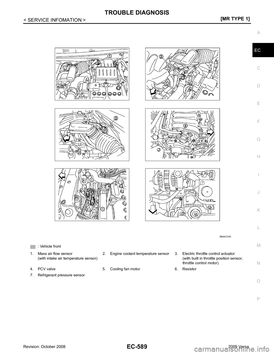
EC
NP
O
: Vehicle front
1. Mass air flow sensor (with intake air temperature sensor) 2. Engine coolant temperature sensor 3. Electric throttle control actuator
(with built in throttle position sensor,
throttle control motor)
4. PCV valve 5. Cooling fan motor 6. Resistor
7. Refrigerant pressure sensor
Page 1961 of 4331

EC
NP
O
Item
DIAGNOSTIC TEST MODE
WORK SUP-
PORT SELF DIAGNOSTIC
RESULT DATA
MONI-
TOR ACTIVE
TEST DTC & SRT
CONFIRMATION
DTC* 1 FREEZE
FRAME
DATA* 2 SRT
STATUS DTC
WORK
SUP-
PORTENGINE CONTROL COMPONENT PARTS
INPUT
Crankshaft position sensor (POS) × × ×
Camshaft position sensor (PHASE) × × ×
Mass air flow sensor × ×
Engine coolant temperature sensor × × × ×
Air fuel ratio (A/F) sensor 1 × × × ×
Heated oxygen sensor 2 × × × ×
Vehicle speed signal × × ×
Accelerator pedal position sensor × ×
Throttle position sensor × × ×
Fuel tank temperature sensor × × ×
EVAP control system pressure sen-
sor × ×
Intake air temperature sensor × × ×
Knock sensor ×
Refrigerant pressure sensor ×
Closed throttle position switch (Ac-
celerator pedal position sensor sig-
nal) ×
Air conditioner switch ×
Park/neutral position (PNP) switch × ×
Stop lamp switch × ×
Battery voltage ×
Load signal ×
Fuel level sensor × ×
ASCD steering switch × ×
ASCD brake switch × ×
ASCD clutch switch × ×
Power steering operation signal ×