light NISSAN TIIDA 2009 Service Repair Manual
[x] Cancel search | Manufacturer: NISSAN, Model Year: 2009, Model line: TIIDA, Model: NISSAN TIIDA 2009Pages: 4331, PDF Size: 58.04 MB
Page 1970 of 4331
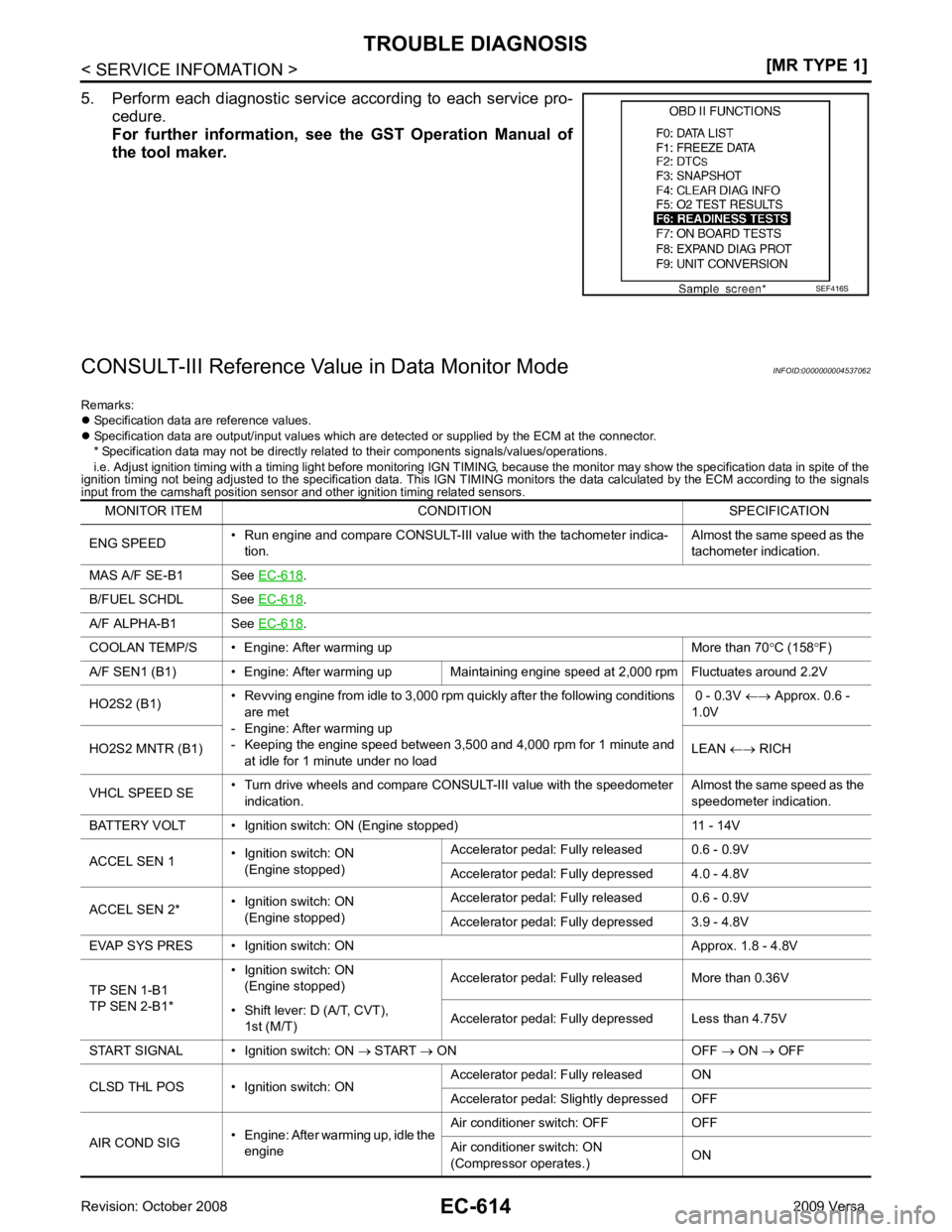
.
B/FUEL SCHDL See EC-618 .
A/F ALPHA-B1 See EC-618 .
COOLAN TEMP/S • Engine: After warming up More than 70 °C (158 °F)
A/F SEN1 (B1) • Engine: After warming up Maintaining engine speed at 2,000 rpm Fluctuates around 2.2V
HO2S2 (B1) • Revving engine from idle to 3,000 rpm quickly after the following conditions
are met
- Engine: After warming up
- Keeping the engine speed between 3,500 and 4,000 rpm for 1 minute and at idle for 1 minute under no load 0 - 0.3V
←→ Approx. 0.6 -
1.0V
HO2S2 MNTR (B1) LEAN ←→ RICH
VHCL SPEED SE • Turn drive wheels and compare CONSULT-III value with the speedometer
indication. Almost the same speed as the
speedometer indication.
BATTERY VOLT • Ignition switch: ON (Engine stopped) 11 - 14V
ACCEL SEN 1 • Ignition switch: ON
(Engine stopped) Accelerator pedal: Fully released 0.6 - 0.9V
Accelerator pedal: Fully depressed 4.0 - 4.8V
ACCEL SEN 2* • Ignition switch: ON
(Engine stopped) Accelerator pedal: Fully released 0.6 - 0.9V
Accelerator pedal: Fully depressed 3.9 - 4.8V
EVAP SYS PRES • Ignition switch: ON Approx. 1.8 - 4.8V
TP SEN 1-B1
TP SEN 2-B1* • Ignition switch: ON
(Engine stopped) Accelerator pedal: Fully released More than 0.36V
• Shift lever: D (A/T, CVT), 1st (M/T) Accelerator pedal: Fully depressed Less than 4.75V
START SIGNAL • Ignition switch: ON → START → ON OFF → ON → OFF
CLSD THL POS • Ignition switch: ON Accelerator
pedal: Fully released ON
Accelerator pedal: Slightly depressed OFF
AIR COND SIG • Engine: After warming up, idle the
engine Air conditioner switch: OFF OFF
Air conditioner switch: ON
(Compressor operates.) ON
Page 1971 of 4331
EC
NP
O
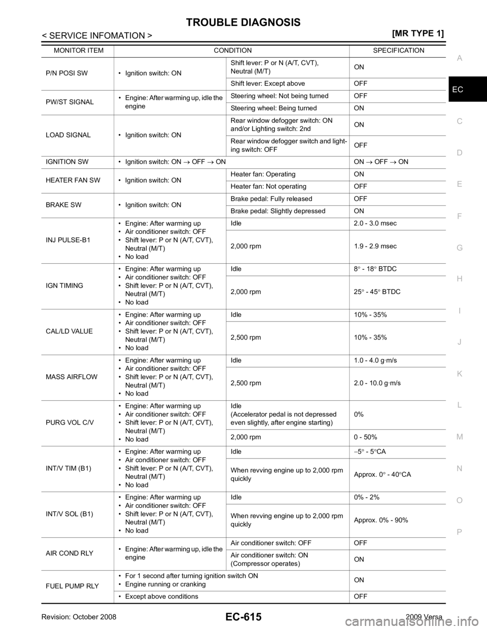
P/N POSI SW • Ignition switch: ON
Shift lever: P or N (A/T, CVT),
Neutral (M/T) ON
Shift lever: Except above OFF
PW/ST SIGNAL • Engine: After warming up, idle the
engine Steering wheel: Not being turned OFF
Steering wheel: Being turned ON
LOAD SIGNAL • Ignition switch: ON Rear window defogger switch: ON
and/or Lighting switch: 2nd ON
Rear window defogger switch and light-
ing switch: OFF OFF
IGNITION SW • Ignition switch: ON → OFF → ON ON → OFF → ON
HEATER FAN SW • Ignition switch: ON Heater fan: Operating ON
Heater fan: Not operating OFF
BRAKE SW • Ignition switch: ON Brake pedal: Fully released OFF
Brake pedal: Slightly depressed ON
INJ PULSE-B1 • Engine: After warming up
• Air conditioner switch: OFF
• Shift lever: P or N (A/T, CVT), Neutral (M/T)
• No load Idle 2.0 - 3.0 msec
2,000 rpm 1.9 - 2.9 msec
IGN TIMING • Engine: After warming up
• Air conditioner switch: OFF
• Shift lever: P or N (A/T, CVT), Neutral (M/T)
• No load Idle 8
° - 18 ° BTDC
2,000 rpm 25 ° - 45 ° BTDC
CAL/LD VALUE • Engine: After warming up
• Air conditioner switch: OFF
• Shift lever: P or N (A/T, CVT),
Neutral (M/T)
• No load Idle 10% - 35%
2,500 rpm 10% - 35%
MASS AIRFLOW • Engine: After warming up
• Air conditioner switch: OFF
• Shift lever: P or N (A/T, CVT), Neutral (M/T)
• No load Idle 1.0 - 4.0 g·m/s
2,500 rpm 2.0 - 10.0 g·m/s
PURG VOL C/V • Engine: After warming up
• Air conditioner switch: OFF
• Shift lever: P or N (A/T, CVT), Neutral (M/T)
• No load Idle
(Accelerator pedal is not depressed
even slightly, after engine starting) 0%
2,000 rpm 0 - 50%
INT/V TIM (B1) • Engine: After warming up
• Air conditioner switch: OFF
• Shift lever: P or N (A/T, CVT), Neutral (M/T)
• No load Idle
−5 ° - 5 °CA
When revving engine up to 2,000 rpm
quickly Approx. 0
° - 40 °CA
INT/V SOL (B1) • Engine: After warming up
• Air conditioner switch: OFF
• Shift lever: P or N (A/T, CVT),
Neutral (M/T)
• No load Idle 0% - 2%
When revving engine up to 2,000 rpm
quickly Approx. 0% - 90%
AIR COND RLY • Engine: After warming up, idle the
engine Air conditioner switch: OFF OFF
Air conditioner switch: ON
(Compressor operates) ON
FUEL PUMP RLY • For 1 second after turning ignition switch ON
• Engine running or cranking ON
• Except above conditions OFF
MONITOR ITEM CONDITION SPECIFICATION
Page 1989 of 4331

EC
NP
O
DTC U1000, U1001 CAN
COMMUNICATION LINE
Description INFOID:0000000004537072
CAN (Controller Area Network) is a serial communication li ne for real time application. It is an on-vehicle mul-
tiplex communication line with high data communication speed and excellent error detection ability. Many elec-
tronic control units are equipped onto a vehicle, and each control unit shares information and links with other
control units during operation (not independent). In CAN communication, control units are connected with 2
communication lines (CAN H line, CAN L line) allowing a high rate of information transmission with less wiring.
Each control unit transmits/receives data but selectively reads required data only.
On Board Diagnosis Logic INFOID:0000000004537073
*1: This self-diagnosis has the one trip detection logic (A/T, CVT).
The MIL will not light up for this self-diagnosis (M/T).
*2: The MIL will not light up for this self-diagnosis.
DTC Confirmation Procedure INFOID:0000000004537074
1. Turn ignition switch ON and wait at least 3 seconds.
2. Check 1st trip DTC.
3. If 1st trip DTC is detected, go to EC-634, " Diagnosis Procedure " .
DTC No.
Trouble diagnosis
name DTC detecting condition Possible cause
U1000* 1
1000* 1
CAN communication
line When ECM is not transmitting or receiving CAN
communication signal of OBD (emission related
diagnosis) for 2 seconds or more. • Harness or connectors
(CAN communication line is open or
shorted.)
U1001* 2
1001* 2 When ECM is not transmitting or receiving CAN
communication signal other than OBD (emission-
related diagnosis) for 2 seconds or more.
Page 1991 of 4331

EC
NP
O
DTC U1010 CAN COMMUNICATION
Description INFOID:0000000004537077
CAN (Controller Area Network) is a serial communication li ne for real time application. It is an on-vehicle mul-
tiplex communication line with high data communication speed and excellent error detection ability. Many elec-
tronic control units are equipped onto a vehicle, and each control unit shares information and links with other
control units during operation (not independent). In CAN communication, control units are connected with 2
communication lines (CAN H line, CAN L line) allowing a high rate of information transmission with less wiring.
Each control unit transmits/receives data but selectively reads required data only.
On Board Diagnosis Logic INFOID:0000000004537078
This self-diagnosis has the one trip detection logic (A/T, CVT).
The MIL will not light up for this self-diagnosis (M/T).
DTC Confirmation Procedure INFOID:0000000004537079
1. Turn ignition switch ON.
2. Check 1st trip DTC.
3. If 1st trip DTC is detected, go to EC-635, " Diagnosis Procedure " .
Diagnosis Procedure INFOID:0000000004537080DTC Confirmation Procedure " .
3. Is the 1st trip DTC U1010 displayed again?
Yes or No Yes >> GO TO 2.
No >> INSPECTION END ECM Re-communicating Function " .
3. Perform EC-572, " VIN Registration " .
4. Perform EC-572, " Accelerator Pedal Released Position Learning " .
5. Perform EC-572, " Throttle Valve Closed Position Learning " .
6. Perform EC-572, " Idle Air Volume Learning " .
>> INSPECTION END
DTC No. Trouble diagnosis name DTC detecting condition Possible cause
U1010
1010 CAN communication bus
When detecting error during the initial diagno-
sis for CAN controller of each control unit. • ECM
Page 2011 of 4331

DTC P0101 MAF SENSOR
EC-655
< SERVICE INFOMATION >
[MR TYPE 1] C
D E
F
G H
I
J
K L
M A EC
NP
O
DTC P0101 MAF SENSOR
Component Description INFOID:0000000004537112
The mass air flow sensor (1) is plac ed in the stream of intake air. It
measures the intake flow rate by measuring a part of the entire
intake flow. The mass air flow sens or controls the temperature of the
hot wire to a certain amount. The heat generated by the hot wire is
reduced as the intake air flows around it. The more air, the greater
the heat loss.
Therefore, the electric current supplied to hot wire is changed to
maintain the temperature of the hot wire as air flow increases. The
ECM detects the air flow by means of this current change.
CONSULT-III Reference Val ue in Data Monitor Mode INFOID:0000000004537113
Specification data are reference values.
On Board Diagnosis Logic INFOID:0000000004537114
DTC Confirmation Procedure INFOID:0000000004537115
Perform PROCEDURE FOR MALFUNCTION A first.
If the DTC cannot be confirmed, perform PROCEDURE FOR MALFUNCTION B.
NOTE:
If DTC Confirmation Procedure has been previously conduc ted, always turn ignition switch OFF and wait at
least 10 seconds before conducting the next test. PBIA9559J
MONITOR ITEM CONDITION SPECIFICATION
MAS A/F SE-B1 • See EC-618 .
CAL/LD VALUE • Engine: After warming up
• Shift lever: P or N (A/T, CVT), Neutral (M/T)
• Air conditioner switch: OFF
• No load Idle 10% - 35%
2,500 rpm 10% - 35%
MASS AIRFLOW • Engine: After warming up
• Shift lever: P or N (A/T, CVT),
Neutral (M/T)
• Air conditioner switch: OFF
• No load Idle 1.0 - 4.0 g·m/s
2,500 rpm 4.0 - 10.0 g·m/s DTC No. Trouble diagnosis name DTC detecting condition Possible cause
P0101
0101 Mass air flow sensor cir-
cuit range/performance A)
A high voltage from the sensor is sent to ECM
under light load driving condition. • Harness or connectors
(Mass air flow sensor circuit is
open or shorted.)
• Mass air flow sensor
• EVAP control system pressure
sensor
• Intake air temperature sensor
B) A low voltage from the sensor is sent to ECM un-
der heavy load driving condition. • Harness or connectors
(Mass air flow sensor circuit is
open or shorted.)
• Intake air leaks
• Mass air flow sensor
• EVAP control system pressure sensor
• Intake air temperature sensor
Page 2019 of 4331

DTC P0102, P0103 MAF SENSOR
EC-663
< SERVICE INFOMATION >
[MR TYPE 1] C
D E
F
G H
I
J
K L
M A EC
NP
O
DTC P0102, P0103 MAF SENSOR
Component Description INFOID:0000000004537121
The mass air flow sensor (1) is plac ed in the stream of intake air. It
measures the intake flow rate by measuring a part of the entire
intake flow. The mass air flow sens or controls the temperature of the
hot wire to a certain amount. The heat generated by the hot wire is
reduced as the intake air flows around it. The more air, the greater
the heat loss.
Therefore, the electric current supplied to hot wire is changed to
maintain the temperature of the hot wire as air flow increases. The
ECM detects the air flow by means of this current change.
CONSULT-III Reference Val ue in Data Monitor Mode INFOID:0000000004537122
Specification data are reference values.
On Board Diagnosis Logic INFOID:0000000004537123
These self-diagnoses have the on e trip detection logic.
FAIL-SAFE MODE When the malfunction is detec ted, the ECM enters fail-safe mode and the MIL lights up.
DTC Confirmation Procedure INFOID:0000000004537124
NOTE:
If DTC Confirmation Procedure has been previously conduc ted, always turn ignition switch OFF and wait at
least 10 seconds before conducting the next test. PBIA9559J
MONITOR ITEM CONDITION SPECIFICATION
MAS A/F SE-B1 See EC-618 .
CAL/LD VALUE • Engine: After warming up
• Shift lever: P or N (A/T, CVT), Neutral (M/T)
• Air conditioner switch: OFF
• No load Idle 10% - 35%
2,500 rpm 10% - 35%
MASS AIRFLOW • Engine: After warming up
• Shift lever: P or N (A/T, CVT),
Neutral (M/T)
• Air conditioner switch: OFF
• No load Idle 1.0 - 4.0 g·m/s
2,500 rpm 4.0 - 10.0 g·m/s DTC No.
Trouble diagnosis
name DTC detecting condition Possible cause
P0102
0102 Mass air flow sensor
circuit low input An excessively low voltage from the sensor is sent
to ECM. • Harness or connectors
(Mass air flow sensor circuit is open or short-
ed.)
• Intake air leaks
• Mass air flow sensor
P0103
0103 Mass air flow sensor
circuit high input An excessively high voltage from the sensor is
sent to ECM. • Harness or connectors
(Mass air flow sensor circuit is open or short-
ed.)
• Mass air flow sensor Detected items Engine operating condition in fail-safe mode
Mass air flow sensor circuit Engine speed will not rise more than 2,400 rpm due to the fuel cut.
Page 2030 of 4331

EC-674< SERVICE INFOMATION >
[MR TYPE 1]
DTC P0117, P0118 ECT SENSOR
DTC P0117, P0118 ECT SENSOR
Component Description INFOID:0000000004537136
The engine coolant temperature sensor is used to detect the engine
coolant temperature. The sensor modifies a voltage signal from the
ECM. The modified signal returns to the ECM as the engine coolant
temperature input. The sensor uses a thermistor which is sensitive to
the change in temperature. The elec trical resistance of the ther-
mistor decreases as temperature increases.
*: This data is reference value and is measured between ECM terminal 38 (Engine
coolant temperature sensor) and ground.
CAUTION:
Do not use ECM ground terminals when measuring in put/output voltage. Doing so may result in dam-
age to the ECM's transistor. Use a ground ot her than ECM terminals, such as the ground.
On Board Diagn osis Logic INFOID:0000000004537137
These self-diagnoses have the one trip detection logic.
FAIL-SAFE MODE
When the malfunction is detected, the ECM enters fail-safe mode and the MIL lights up. SEF594K
Engine coolant temperature
°C ( °F) Voltage* V Resistance k
Ω
–10 (14) 4.4 7.0 - 11.4 20 (68) 3.5 2.1 - 2.9
50 (122) 2.2 0.68 - 1.00
90 (194) 0.9 0.236 - 0.260 SEF012P
DTC No.
Trouble Diagnosis
Name DTC Detecting Condit
ion Possible Cause
P0117
0117 Engine coolant tem-
perature sensor cir-
cuit low input An excessively low voltage from the sensor is
sent to ECM. • Harness or connectors
(Engine coolant temperature sensor circuit is
open or shorted.)
• Engine coolant temperature sensor
P0118
0118 Engine coolant tem-
perature sensor cir-
cuit high input An excessively high voltage from the sensor is
sent to ECM.
Page 2035 of 4331

DTC P0122, P
0123 TP SENSOR
EC-679
< SERVICE INFOMATION >
[MR TYPE 1] C
D E
F
G H
I
J
K L
M A EC
NP
O
DTC P0122, P0123 TP SENSOR
Component Description INFOID:0000000004537143
Electric throttle control actuator consists of throttle control motor,
throttle position sensor, etc. The throttle position sensor responds to
the throttle valve movement.
The throttle position sensor has two sensors. These sensors are a
kind of potentiometers which transform the throttle valve position into
output voltage, and emit the voltage signal to the ECM. In addition,
these sensors detect the opening and closing speed of the throttle
valve and feed the voltage signals to the ECM. The ECM judges the
current opening angle of the throttle valve from these signals and the
ECM controls the throttle control motor to make the throttle valve
opening angle properly in response to driving condition.
CONSULT-III Reference Val ue in Data Monitor Mode INFOID:0000000004537144
Specification data are reference values.
*: Throttle position sensor 2 signal is converted by ECM internally. Thus, it differs from ECM terminal voltage signal.
On Board Diagnosis Logic INFOID:0000000004537145
These self-diagnoses have the on e trip detection logic.
NOTE:
If DTC P0122 or P0123 is displayed with DTC P0643, first perform the trouble diagnosis for DTC P0643.
Refer to EC-874 .
FAIL-SAFE MODE When the malfunction is detected, ECM ent ers fail-safe mode and the MIL lights up.
DTC Confirmation Procedure INFOID:0000000004537146
NOTE:
If DTC Confirmation Procedure has been previously conduc ted, always turn ignition switch OFF and wait at
least 10 seconds before conducting the next test.
TESTING CONDITION:
Before performing the following procedure, confirm that battery voltage is more than 8V at idle.
1. Start engine and let it idle for 1 second.
2. Check DTC.
3. If DTC is detected, go to EC-681, " Diagnosis Procedure " . PBIB0145E
MONITOR ITEM CONDITION SPECIFICATION
TP SEN 1-B1
TP SEN 2-B1* • Ignition switch: ON
(Engine stopped)
• Shift lever: D (A/T, CVT),
1st (M/T) Accelerator pedal: Fully released More than 0.36V
Accelerator pedal: Fully depressed Less than 4.75V DTC No. Trouble diagnosis name DTC detecting condition Possible cause
P0122
0122 Throttle position sensor
2 circuit low input An excessively low voltage from the TP sensor
2 is sent to ECM. • Harness or connectors
(TP sensor 2 circuit is open or shorted.)
• Electric throttle control actuator (TP sensor 2)
P0123
0123 Throttle position sensor
2 circuit high input An excessively high voltage from the TP sensor
2 is sent to ECM. Engine operation condition in fail-safe mode
The ECM controls the electric throttle control actuator in regulating the throttle opening in order for the idle position to be within +10
degrees.
The ECM regulates the opening speed of the throttle valve to be slower than the normal condition.
So, the acceleration will be poor.
Page 2116 of 4331

EC-760< SERVICE INFOMATION >
[MR TYPE 1]
DTC P0222, P0223 TP SENSOR
DTC P0222, P0223 TP SENSOR
Component Description INFOID:0000000004537246
Electric throttle control actuator consists of throttle control motor,
throttle position sensor, etc. The throttle position sensor responds to
the throttle valve movement.
The throttle position sensor has two sensors. These sensors are a
kind of potentiometers which transform the throttle valve position into
output voltage, and emit the voltage signal to the ECM. In addition,
these sensors detect the opening and closing speed of the throttle
valve and feed the voltage signals to the ECM. The ECM judges the
current opening angle of the throttle valve from these signals and the
ECM controls the throttle control motor to make the throttle valve
opening angle properly in response to driving condition.
CONSULT-III Reference Value in Data Monitor Mode INFOID:0000000004537247
Specification data are reference values.
*: Throttle position sensor 2 signal is converted by ECM internally. Thus, it differs from ECM terminal voltage signal.
On Board Diagn osis Logic INFOID:0000000004537248
These self-diagnoses have the one trip detection logic.
NOTE:
If DTC P0222 or P0223 is displayed with DTC P0643, first perform the trouble diagnosis for DTC P0643.
Refer to EC-874 .
FAIL-SAFE MODE
When the malfunction is detected, the ECM enters fail-safe mode and the MIL lights up.
DTC Confirmation Procedure INFOID:0000000004537249
NOTE:
If DTC Confirmation Procedure has been previously conduc ted, always turn ignition switch OFF and wait at
least 10 seconds before conducting the next test.
TESTING CONDITION:
Before performing the following procedure, confirm that battery voltage is more than 8V at idle. PBIB0145E
MONITOR ITEM CONDITION SPECIFICATION
TP SEN 1-B1
TP SEN 2-B1* • Ignition switch: ON
(Engine stopped) Accelerator pedal: Fully released More than 0.36V
• Shift lever: D (A/T, CVT), 1st (M/T) Accelerator pedal: Fully depressed Less than 4.75VDTC No. Trouble diagnosis name DTC detecting condition Possible cause
P0222
0222 Throttle position sensor
1 circuit low input An excessively low voltage from the TP sensor
1 is sent to ECM. • Harness or connectors
(TP sensor 1 circuit is open or shorted.)
(APP sensor 2 circuit is shorted.)
• Electric throttle control actuator (TP sensor 1)
• Accelerator pedal position sensor
(APP sensor 2)
P0223
0223 Throttle position sensor
1 circuit high input An excessively high voltage from the TP sensor
1 is sent to ECM. Engine operation condition in fail-safe mode
The ECM controls the electric throttle control actuator in regulating the throttle opening in order for the idle position to be within +10
degrees.
The ECM regulates the opening speed of the throttle valve to be slower than the normal condition.
So, the acceleration will be poor.
Page 2121 of 4331

EC
NP
O
DTC P0300 - P0304 MULTIPLE CYLINDER
MISFIRE, NO. 1 - 4 CYLINDER
MISFIRE
On Board Diagnosis Logic INFOID:0000000004537254
When a misfire occurs, engine speed will fluctuate. If the engine speed fluctuates enough to cause the crank-
shaft position (CKP) sensor (POS) signal to vary , ECM can determine that a misfire is occurring.
The misfire detection logic consists of the following two conditions.
1. One Trip Detection Logic (Three Way Catalyst Damage) On the 1st trip that a misfire condition occurs that can damage the three way catalyst (TWC) due to over-
heating, the MIL will blink.
When a misfire condition occurs, the ECM monitors the CKP sensor (POS) signal every 200 engine revo-
lutions for a change.
When the misfire condition decreases to a level t hat will not damage the TWC, the MIL will turn off.
If another misfire condition occurs that can damage the TWC on a second trip, the MIL will blink.
When the misfire condition decreases to a level t hat will not damage the TWC, the MIL will remain on.
If another misfire condition occurs that can damage the TWC, the MIL will begin to blink again.
2. Two Trip Detection Logic (Exhaust quality deterioration) For misfire conditions that will not damage the TWC (but will affect vehicle emissions), the MIL will only
light when the misfire is detected on a second trip. Du ring this condition, the ECM monitors the CKP sen-
sor signal every 1,000 engine revolutions.
A misfire malfunction can be detected on any one cylinder or on multiple cylinders.
DTC Confirmation Procedure INFOID:0000000004537255
CAUTION:
Always drive vehicle in safe manner according to traf fic conditions and obey all traffic laws when driv-
ing.
NOTE:
If DTC Confirmation Procedure has been previously conduc ted, always turn ignition switch OFF and wait at
least 10 seconds before conducting the next test.
1. Start engine and warm it up to normal operating temperature.
2. Turn ignition switch OFF and wait at least 10 seconds.
3. Restart engine and let it idle for about 15 minutes.
4. Check 1st trip DTC.
5. If 1st trip DTC is detected, go to EC-766, " Diagnosis Procedure " .
NOTE:
If 1st trip DTC is not detected during above proc edure, performing the following procedure is advised.
a. Turn ignition switch OFF and wait at least 10 seconds.
b. Start engine and drive the vehicle under the similar conditi ons to (1st trip) Freeze Frame Data for a certain
time. Refer to table below. Sensor Input Signal to ECM ECM function
Crankshaft position sensor (POS) Engine speed On board diagnosis of misfire DTC No. Trouble diagnosis name DTC detecting condition Possible cause
P0300
0300 Multiple cylinder misfire
detected Multiple cylinder misfire.
• Improper spark plug
• Insufficient compression
• Incorrect fuel pressure
• Fuel injector circuit is open or shorted
• Fuel injector
• Intake air leak
• The ignition signal circuit is open or shorted
• Lack of fuel
• Drive plate or flywheel
• Air fuel ratio (A/F) sensor 1
• Incorrect PCV hose connection
P0301
0301 No.1 cylinder misfire de-
tected No. 1 cylinder misfires.
P0302
0302 No. 2 cylinder misfire
detected No. 2 cylinder misfires.
P0303
0303 No. 3 cylinder misfire
detected No. 3 cylinder misfires.
P0304
0304 No. 4 cylinder misfire
detected No. 4 cylinder misfires.