low oil pressure NISSAN TIIDA 2009 Service User Guide
[x] Cancel search | Manufacturer: NISSAN, Model Year: 2009, Model line: TIIDA, Model: NISSAN TIIDA 2009Pages: 4331, PDF Size: 58.04 MB
Page 286 of 4331
AT
N
O P
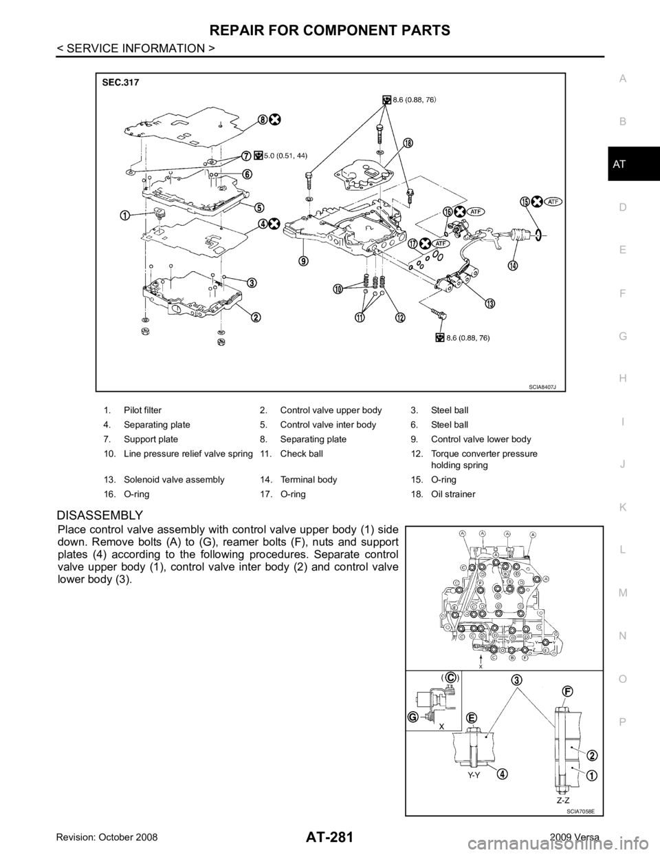
DISASSEMBLY
Place control valve assembly with control valve upper body (1) side
down. Remove bolts (A) to (G), reamer bolts (F), nuts and support
plates (4) according to the following procedures. Separate control
valve upper body (1), control valve inter body (2) and control valve
lower body (3). 1. Pilot filter 2. Control valve upper body 3. Steel ball
4. Separating plate 5. Control valve inter body 6. Steel ball
7. Support plate 8. Separating plate 9. Control valve lower body
10. Line pressure relief valve spring 11. Check ball 12. Torque converter pressure holding spring
13. Solenoid valve assembly 14. Terminal body 15. O-ring
16. O-ring 17. O-ring 18. Oil strainer SCIA7058E
Page 934 of 4331
![NISSAN TIIDA 2009 Service User Guide CO-40< SERVICE INFORMATION >
[MR18DE]
RADIATOR
Checking Radiator Cap INFOID:0000000004305238
• Check valve seat of radiator cap.
- Check if valve seat is swollen to the extent that the e](/img/5/57398/w960_57398-933.png "NISSAN TIIDA 2009 Service User Guide CO-40< SERVICE INFORMATION >
[MR18DE]
RADIATOR
Checking Radiator Cap INFOID:0000000004305238
• Check valve seat of radiator cap.
- Check if valve seat is swollen to the extent that the e")
CO-40< SERVICE INFORMATION >
[MR18DE]
RADIATOR
Checking Radiator Cap INFOID:0000000004305238
• Check valve seat of radiator cap.
- Check if valve seat is swollen to the extent that the edge of the plunger cannot be seen when watching it vertically from the top.
- Check if valve seat has no soil and damage.
• Pull negative-pressure valve to open it, and make sure that it is completely closed when released.
- Make sure that there is no dirt or damage on the valve seat of radi-
ator cap negative-pressure valve.
- Make sure that the valve operates properly in the opening and closing conditions.
• Check radiator cap relief pressure using Tool.
- When connecting the radiator cap to the tester, apply water or coolant to the cap seal surface.
- Replace the radiator cap if ther e is an abnormality in the negative-
pressure valve, or if the open-valve pr essure is outside of the standard values.
• Replace radiator cap if there it does not comply to specifications to the above three checks.
CAUTION:
When installing radiator cap, thoroughly wipe out the radiator filler neck to remove any waxy residue
or foreign material.
Checking Radiator INFOID:0000000004305239
Check radiator for mud or clogging. If necessary, clean radiator as follows.
• Be careful not to bend or damage radiator fins.
• When radiator is cleaned without removal, remove all surrounding parts such as cooling fan, radiator shroud and horns. Then tape harness and connectors to prevent water from entering.
1. Apply water by hose to the back side of the radiator core vertically downward.
2. Apply water again to all radiator core surface once per minute.
3. Stop washing if any stains no longer flow out from radiator.
4. Blow air into the back side of radiator core vertically downward. • Use compressed air lower than 490 kPa (4.9 bar, 5 kg/cm 2
, 71 psi) and keep distance more than 30 cm
(11.8 in).
5. Blow air again into all the radiator core surfaces once per minute until no water sprays out. PBIC2816E
SMA967B
Tool number : EG17650301 (J-33984-A)
Standard: 78 – 98 kPa (0.78 - 0.98 bar, 0.8 – 1.0 kg/cm 2
, 11
– 14 psi)
Limit: 59 kPa (0.59 bar, 0.6 kg/cm 2
, 9 psi) WBIA0570E
Page 977 of 4331

CVT
N
O P
TROUBLE DIAGNOSIS
DTC Inspection Priority Chart INFOID:0000000004666880
If some DTCs are displayed at the same time, perform inspections one by one based on the following priority
chart.
NOTE:
If DTC “U1000 CAN COMM CIRCUIT” is displayed with other DTCs, first perform the trouble diagnosis
for “DTC U1000 CAN COMMUNICATION LINE”. Refer to CVT-60 .
Fail-Safe INFOID:0000000004666881
The TCM has an electrical fail-safe mode. This mode make s it possible to operate even if there is an error in a
main electronic control input/output signal circuit.
FAIL-SAFE FUNCTION If any malfunction occurs in a sensor or solenoid, th is function controls the CVT to make driving possible.
Output Speed Sensor (Secondary Speed Sensor) The shift pattern is changed in accordance with throttle position when an unexpected signal is sent from the
output speed sensor (secondary speed sensor) to the TCM. The overdrive-off mode is inhibited, and the tran-
saxle is put in “D”.
Input Speed Sensor (Primary Speed Sensor) The shift pattern is changed in accordance with throttle position and secondary speed (vehicle speed) when
an unexpected signal is sent from the input speed sensor (primary speed sensor) to the TCM. The sport mode
is inhibited, and the transaxle is put in “D”.
PNP Switch If an unexpected signal is sent from the PNP switch to the TCM, the transaxle is put in “D”.
CVT Fluid Temperature Sensor If an unexpected signal is sent from the CVT fluid temper ature sensor to the TCM, the gear ratio in use before
receiving the unexpected signal is maintained or the gear ratio is controlled to keep engine speed under 3500
rpm.
Transmission Fluid Pressure Sens or A (Secondary Pressure Sensor)
• If an unexpected signal is sent from the transmission fl uid pressure sensor A (secondary pressure sensor) to
the TCM, the secondary pressure feedback control is stopped and the offset value obtained before the non-
standard condition occurs is used to control line pressure.
• If transmission fluid pressure sensor A (secondary pre ssure sensor) error signal is input to TCM, secondary
pressure feedback control stops, but line pressure is controlled normally.
Pressure Control Solenoid A (Line Pressure Solenoid) If an unexpected signal is sent from the solenoid to t he TCM, the pressure control solenoid A (line pressure
solenoid) is turned OFF to achieve the maximum fluid pressure.
Pressure Control Solenoid B (Secondary Pressure Solenoid) If an unexpected signal is sent from the solenoid to t he TCM, the pressure control solenoid B (secondary pres-
sure solenoid) is turned OFF to achieve the maximum fluid pressure.
Torque Converter Clutch Solenoid If an unexpected signal is sent from the solenoid to t he TCM, the torque converter clutch solenoid is turned
OFF to cancel the lock-up.
Step Motor If an unexpected signal is sent from the step motor to the TCM, the step motor coil phases “A” through “D” are
all turned OFF to hold the gear ratio used right before the non-standard condition occurred.
CVT Lock-up Select Solenoid Priority Detected items (DTC)
1 U1000 CAN communication line
2 Except above
Page 986 of 4331
![NISSAN TIIDA 2009 Service User Guide CVT-42< SERVICE INFORMATION >
[RE0F08A]
TROUBLE DIAGNOSIS
6. While holding down the foot brake, gradually press down the accelerator pedal.
7. Quickly read off the stall speed, and the](/img/5/57398/w960_57398-985.png "NISSAN TIIDA 2009 Service User Guide CVT-42< SERVICE INFORMATION >
[RE0F08A]
TROUBLE DIAGNOSIS
6. While holding down the foot brake, gradually press down the accelerator pedal.
7. Quickly read off the stall speed, and the")
CVT-42< SERVICE INFORMATION >
[RE0F08A]
TROUBLE DIAGNOSIS
6. While holding down the foot brake, gradually press down the accelerator pedal.
7. Quickly read off the stall speed, and then quickly remove your foot from the accelerator pedal.
CAUTION:
Do not hold down the accelerator pedal for more than 5 sec-
onds during this test.
8. Move the selector lever to the “N” position.
9. Cool down the CVT fluid. CAUTION:
Run the engine at idle for at least 1 minute.
10. Repeat steps 6 through 9 with selector lever in “R” position.
Judgement Stall Test
O: Stall speed within standard value position.
H: Stall speed is higher than standard value.
L: Stall speed is lower than standard value.
LINE PRESSURE TEST
Line Pressure Test Port
Line Pressure Test Procedure
1. Inspect the amount of engine oil and replenish if necessary.
2. Drive the car for about 10 minutes to warm it up so that the CVT fluid reaches in the range of 50 to 80°C
(122 to 176 °F), then inspect the amount of CVT fluid and replenish if necessary.
NOTE: Stall speed: 2,600 - 3,150 rpm SAT514G
SAT771B
Selector lever position
Expected problem location
“D” “R”
Stall rotation H O • Forward clutch
O H • Reverse brake L L • Engine and torque converter one-way clutch
H H • Line pressure low
• Primary pulley
• Secondary pulley
• Steel belt SCIA6184E
Page 987 of 4331
CVT
N
O P
The CVT fluid temperature rises in the range of 50 - 80
°C (122 - 176 °F) during 10 minutes of driving.
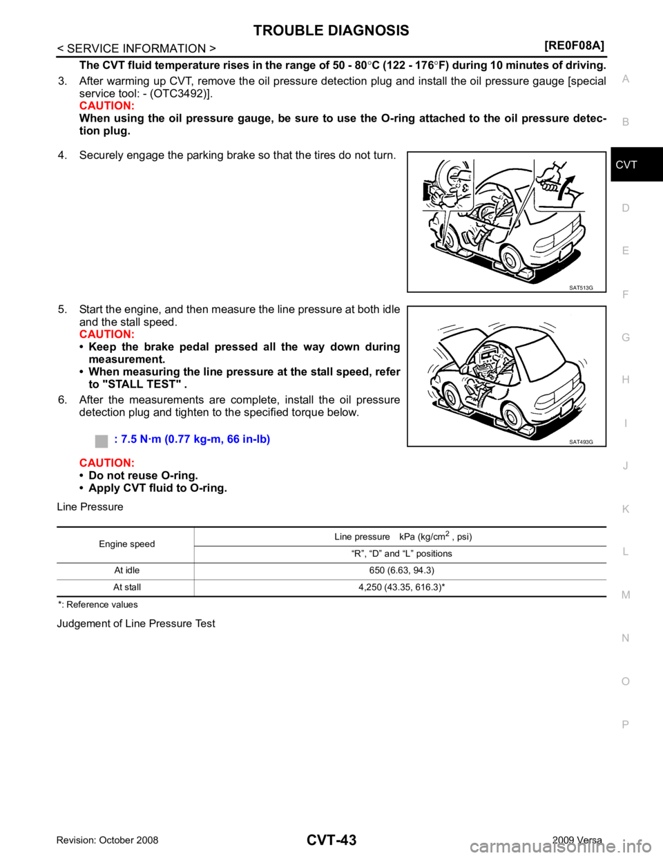
3. After warming up CVT, remove the oil pressure detection plug and install the oil pressure gauge [special service tool: - (OTC3492)].
CAUTION:
When using the oil pressure gauge, be sure to use the O-ring attached to the oil pressure detec-
tion plug.
4. Securely engage the parking brake so that the tires do not turn.
5. Start the engine, and then measure the line pressure at both idle and the stall speed.
CAUTION:
• Keep the brake pedal pressed all the way down during
measurement.
• When measuring the line pressure at the stall speed, refer
to "STALL TEST" .
6. After the measurements are complete, install the oil pressure detection plug and tighten to the specified torque below.
CAUTION:
• Do not reuse O-ring.
• Apply CVT fluid to O-ring.
Line Pressure
*: Reference values
Judgement of Line Pressure Test
Page 988 of 4331
![NISSAN TIIDA 2009 Service User Guide CVT-44< SERVICE INFORMATION >
[RE0F08A]
TROUBLE DIAGNOSIS
Road Test INFOID:0000000004666886
DESCRIPTION
• The purpose of the test is to determine overall performance of CVT and analyze causes of pro](/img/5/57398/w960_57398-987.png "NISSAN TIIDA 2009 Service User Guide CVT-44< SERVICE INFORMATION >
[RE0F08A]
TROUBLE DIAGNOSIS
Road Test INFOID:0000000004666886
DESCRIPTION
• The purpose of the test is to determine overall performance of CVT and analyze causes of pro")
CVT-44< SERVICE INFORMATION >
[RE0F08A]
TROUBLE DIAGNOSIS
Road Test INFOID:0000000004666886
DESCRIPTION
• The purpose of the test is to determine overall performance of CVT and analyze causes of problems.
• The road test consists of the following three parts:
1. “Check Before Engine Is Started” CVT-45 .
2. “Check at Idle” CVT-45 .
3. “Cruise Test” CVT-47 .
Judgement Possible cause
Idle speed Low for all positions
(“P”, “R”, “N”, “D”, “L”) Possible causes include malfunctions in the pressure supply system and low oil pump output.
For example
• Oil pump wear
• Pressure regulator valve or plug sticking or spring fatigue
• Oil strainer ⇒ oil pump ⇒ pressure regulator valve passage oil leak
• Engine idle speed too low
Only low for a specific
position Possible causes include an oil pressure leak in a passage or device related to the position after
the pressure is distributed by the manual valve.
High Possible causes include a sensor malfunction or malfunction in the line pressure adjustment
function.
For example
• Accelerator pedal position signal malfunction
• CVT fluid temperature sensor malfunction
• Pressure control solenoid A (line pressure solenoid) malfunction (sticking in OFF state, filter
clog, cut line)
• Pressure regulator valve or plug sticking
Stall speed Line pressure does
not rise higher than
the line pressure for
idle. Possible causes include a sensor malfunction or malfunction in the pressure adjustment func-
tion.
For example
• Accelerator pedal position signal malfunction
• TCM malfunction
• Pressure control solenoid A (line pressure solenoid) malfunction (shorting, sticking in ON state)
• Pressure regulator valve or plug sticking
The pressure rises,
but does not enter the
standard position. Possible causes include malfunctions in the pressure supply system and malfunction in the pres-
sure adjustment function.
For example
• Accelerator pedal position signal malfunction
• Pressure control solenoid A (line pressure solenoid) malfunction (sticking, filter clog)
• Pressure regulator valve or plug sticking
Only low for a specific
position Possible causes include an oil pressure leak in a passage or device related to the position after
the pressure is distributed by the manual valve. SAT786A
Page 1043 of 4331

CVT
N
O P
DTC P0745 LINE PRESSURE SOLENOID VALVE
Description INFOID:0000000004666974
• The pressure control solenoid valve A (line pressure solenoid valve) is included in the control valve assem- bly.
• The pressure control solenoid valve A (line pressure solenoid valve) regulates the oil pump discharge pres-
sure to suit the driving condition in response to a signal sent from the TCM.
CONSULT-III Reference Val ue in Data Monitor Mode INFOID:0000000004666975
Remarks: Specification data are reference values.
On Board Diagnosis Logic INFOID:0000000004666976
• This is an OBD-II self-diagnostic item.
• Diagnostic trouble code “P0745 L/PRESS SOL/CIRC” with CONSULT-III is detected under the following
conditions.
- TCM detects an improper voltage drop when it tries to operate the solenoid valve.
- When TCM compares target value with monitor value and detects an irregularity.
Possible Cause INFOID:0000000004666977
• Harness or connectors (Solenoid circuit is open or shorted.)
• Pressure control solenoid valve A (Line pressure solenoid valve)
DTC Confirmation Procedure INFOID:0000000004666978
NOTE:
If “DTC Confirmation Procedure” has been previously performed, alw ays turn ignition switch OFF and
wait at least 10 seconds before performing the next test.
After the repair, perform the following procedure to confirm the malfunction is eliminated.
WITH CONSULT-III
1. Turn ignition switch ON and select “DATA MO NITOR” mode for “TRANSMISSION” with CONSULT-III.
2. Start engine and wait at least 5 seconds.
3. If DTC is detected, go to CVT-101, " Diagnosis Procedure " .
WITH GST
Follow the procedure “WITH CONSULT-III”. Item name Condition Display value (Approx.)
ISOLT2 Release your foot from the accelerator pedal. 0.8 A
Press the accelerator pedal all the way down. 0.0 A
Page 1085 of 4331

CVT
N
O P
DTC P1777 STEP MOTOR - CIRCUIT
Description INFOID:0000000004667069
• The step motor is included in the control valve assembly.
• The step motor changes the step with turning 4 coils ON/OF F according to the signal from TCM. As a result,
the flow of line pressure to primary pu lley is changed and pulley ratio is controlled
CONSULT-III Reference Val ue in Data Monitor Mode INFOID:0000000004667070
Remarks: Specification data are reference values.
On Board Diagnosis Logic INFOID:0000000004667071
• This is an OBD-II self-diagnostic item.
• Diagnostic trouble code “P1777 STEP MOTR CIRC” with CONSULT-III is detected under the following con-
ditions.
- When operating step motor ON and OFF, there is no proper change in the voltage of TCM terminal which corresponds to it.
Possible Cause INFOID:0000000004667072
• Step motor
• Harness or connectors
(Step motor circuit is open or shorted.)
DTC Confirmation Procedure INFOID:0000000004667073
CAUTION:
Always drive vehicle at a safe speed.
NOTE:
If “DTC Confirmation Procedure” has been previously performed, alw ays turn ignition switch OFF and
wait at least 10 seconds before performing the next test.
After the repair, touch “ERASE” on “SELF-DIAG RESU LTS” and then perform the following procedure to con-
firm the malfunction is eliminated.
WITH CONSULT-III
1. Turn ignition switch ON and select “DATA MO NITOR” mode for “TRANSMISSION” with CONSULT-III.
2. Drive vehicle for at least 5 consecutive seconds.
3. If DTC is detected, go to CVT-143, " Diagnosis Procedure " .
WITH GST
Follow the procedure “WITH CONSULT-III”. Item name Condition Display value (Approx.)
STM STEP
During driving−
20 step - 180 step
SMCOIL A
Changes ON⇔OFF.
SMCOIL B
SMCOIL C
SMCOIL D
Page 1165 of 4331
![NISSAN TIIDA 2009 Service User Guide TROUBLE DIAGNOSIS
CVT-221
< SERVICE INFORMATION >
[RE0F08B] D
E
F
G H
I
J
K L
M A
B CVT
N
O P
6. While holding down the foot brake, gradually press down the
accelerator pedal.
7. Quickly rea](/img/5/57398/w960_57398-1164.png "NISSAN TIIDA 2009 Service User Guide TROUBLE DIAGNOSIS
CVT-221
< SERVICE INFORMATION >
[RE0F08B] D
E
F
G H
I
J
K L
M A
B CVT
N
O P
6. While holding down the foot brake, gradually press down the
accelerator pedal.
7. Quickly rea")
TROUBLE DIAGNOSIS
CVT-221
< SERVICE INFORMATION >
[RE0F08B] D
E
F
G H
I
J
K L
M A
B CVT
N
O P
6. While holding down the foot brake, gradually press down the
accelerator pedal.
7. Quickly read off the stall speed, and then quickly remove your foot from the accelerator pedal.
CAUTION:
Do not hold down the accelerat or pedal for more than 5 sec-
onds during this test.
8. Move the selector lever to the “N” position.
9. Cool down the CVT fluid. CAUTION:
Run the engine at idle for at least 1 minute.
10. Repeat steps 6 through 9 with selector lever in “R” position.
Judgement Stall Test
O: Stall speed within standard value position.
H: Stall speed is higher than standard value.
L: Stall speed is lower than standard value.
LINE PRESSURE TEST
Line Pressure Test Port
Line Pressure Test Procedure 1. Inspect the amount of engine oil and replenish if necessary.
2. Drive the car for about 10 minutes to warm it up so that the CVT fluid reaches in the range of 50 to 80°C
(122 to 176 °F), then inspect the amount of CVT fluid and replenish if necessary.
NOTE: Stall speed:
CVT-357, " Stall Speed "
SAT514G
SAT771B
Selector lever position
Expected problem location
“D” “R”
Stall rotation H O • Forward clutch
O H • Reverse brake L L • Engine and torque converter one-way clutch
H H • Line pressure low
• Primary pulley
• Secondary pulley
• Steel belt SCIA6184E
Page 1166 of 4331
![NISSAN TIIDA 2009 Service User Guide CVT-222< SERVICE INFORMATION >
[RE0F08B]
TROUBLE DIAGNOSIS
The CVT fluid temperature rises in the range of 50 - 80 °C (122 - 176 °F) during 10 minutes of driving.
3. After warming up CVT, remove the](/img/5/57398/w960_57398-1165.png "NISSAN TIIDA 2009 Service User Guide CVT-222< SERVICE INFORMATION >
[RE0F08B]
TROUBLE DIAGNOSIS
The CVT fluid temperature rises in the range of 50 - 80 °C (122 - 176 °F) during 10 minutes of driving.
3. After warming up CVT, remove the")
CVT-222< SERVICE INFORMATION >
[RE0F08B]
TROUBLE DIAGNOSIS
The CVT fluid temperature rises in the range of 50 - 80 °C (122 - 176 °F) during 10 minutes of driving.
3. After warming up CVT, remove the oil pressure detection plug and install the oil pressure gauge [special service tool: - (OTC3492)].
CAUTION:
When using the oil pressure gauge, be sure to u se the O-ring attached to the oil pressure detec-
tion plug.
4. Securely engage the parking brake so that the tires do not turn.
5. Start the engine, and then measure the line pressure at both idle and the stall speed.
CAUTION:
• Keep the brake pedal pressed all the way down during
measurement.
• When measuring the line pressure at the stall speed, refer
to "STALL TEST" .
6. After the measurements are complete, install the oil pressure detection plug and tighten to the specified torque below.
CAUTION:
• Do not reuse O-ring.
• Apply CVT fluid to O-ring.
Line Pressure
Judgement of Line Pressure Test SAT513G
: 7.5 N·m (0.77 kg-m, 66 in-lb)
SAT493G
Engine speed
Line pressure kPa (kg/cm
2
, psi)
“R”, “D” and “L” positions
At idle CVT-357, " Line Pressure "
At stall