washer fluid NISSAN TIIDA 2009 Service User Guide
[x] Cancel search | Manufacturer: NISSAN, Model Year: 2009, Model line: TIIDA, Model: NISSAN TIIDA 2009Pages: 4331, PDF Size: 58.04 MB
Page 1312 of 4331
System Description " .
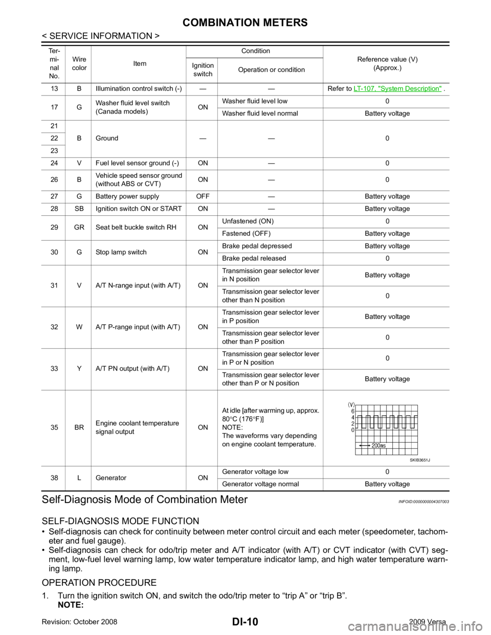
17 G Washer fluid level switch
(Canada models) ONWasher fluid level low 0
Washer fluid level normal Battery voltage
21 B Ground — — 0
22
23
24 V Fuel level sensor ground (-) ON — 0
26 B Vehicle speed sensor ground
(without ABS or CVT) ON — 0
27 G Battery power supply OFF — Battery voltage
28 SB Ignition switch ON or START ON — Battery voltage
29 GR Seat belt buckle switch RH ON Unfastened (ON) 0
Fastened (OFF) Battery voltage
30 G Stop lamp switch ON Brake pedal depressed Battery voltage
Brake pedal released 0
31 V A/T N-range input (with A/T) ON Transmission gear selector lever
in N position Battery voltage
Transmission gear selector lever
other than N position 0
32 W A/T P-range input (with A/T) ON Transmission gear selector lever
in P position Battery voltage
Transmission gear selector lever
other than P position 0
33 Y A/T PN output (with A/T) ON Transmission gear selector lever
in P or N position 0
Transmission gear selector lever
other than P or N position Battery voltage
35 BR Engine coolant temperature
signal output ONAt idle [after warming up, approx.
80 °C (176 °F)]
NOTE:
The waveforms vary depending
on engine coolant temperature.
38 L Generator ON Generator voltage low 0
Generator voltage normal Battery voltage
Ter-
mi-
nal
No. Wire
color Item Condition
Reference value (V)
(Approx.)
Ignition
switch Operation or condition
Page 3145 of 4331
Com-
ponent " .
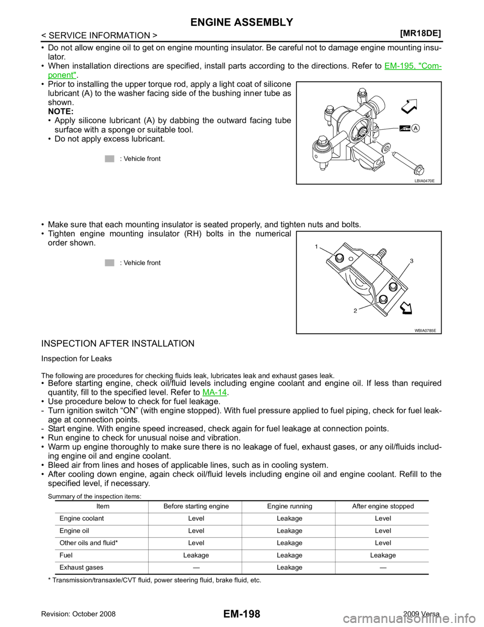
• Prior to installing the upper torque rod, apply a light coat of silicone lubricant (A) to the washer facing side of the bushing inner tube as
shown.
NOTE:
• Apply silicone lubricant (A) by dabbing the outward facing tube
surface with a sponge or suitable tool.
• Do not apply excess lubricant.
• Make sure that each mounting insulator is seated properly, and tighten nuts and bolts.
• Tighten engine mounting insulator (RH) bolts in the numerical order shown.
INSPECTION AFTER INSTALLATION
Inspection for Leaks
The following are procedures for checking fluids leak, lubricates leak and exhaust gases leak.
• Before starting engine, check oil/fluid levels incl uding engine coolant and engine oil. If less than required
quantity, fill to the specified level. Refer to MA-14 .
• Use procedure below to check for fuel leakage.
- Turn ignition switch “ON” (with engine stopped). With fuel pressure applied to fuel piping, check for fuel leak-
age at connection points.
- Start engine. With engine speed increased, che ck again for fuel leakage at connection points.
• Run engine to check for unusual noise and vibration.
• Warm up engine thoroughly to make sure there is no leak age of fuel, exhaust gases, or any oil/fluids includ-
ing engine oil and engine coolant.
• Bleed air from lines and hoses of applicable lines, such as in cooling system.
• After cooling down engine, again check oil/fluid levels including engine oil and engine coolant. Refill to the specified level, if necessary.
Summary of the inspection items:
* Transmission/transaxle/CVT fluid, power steering fluid, brake fluid, etc. : Vehicle front
Page 3262 of 4331
GI
N
O P
SYMBOLS
How to Follow Trouble Diagnosis INFOID:0000000004307360
DESCRIPTION NOTICE:
Trouble diagnoses indicate work procedures required to diagnose problems effectively. Observe the following
instructions before diagnosing.
1. Before performing trouble diagno ses, read the “Preliminary Check” , the “Symptom Chart” or the
“Work Flow”.
2. After repairs, re-check that the prob lem has been completely eliminated.
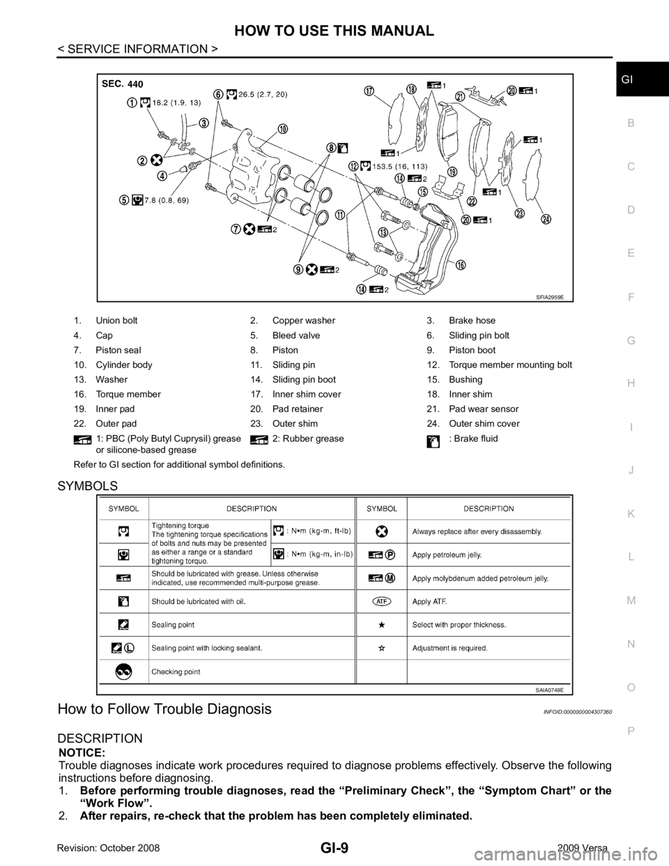
1. Union bolt 2. Copper washer 3. Brake hose
4. Cap 5. Bleed valve 6. Sliding pin bolt
7. Piston seal 8. Piston 9. Piston boot
10. Cylinder body 11. Sliding pin 12. Torque member mounting bolt
13. Washer 14. Sliding pin boot 15. Bushing
16. Torque member 17. Inner shim cover 18. Inner shim
19. Inner pad 20. Pad retainer 21. Pad wear sensor
22. Outer pad 23. Outer shim 24. Outer shim cover 1: PBC (Poly Butyl Cuprysil) grease
or silicone-based grease 2: Rubber grease : Brake fluid
Refer to GI section for additional symbol definitions.
Page 3729 of 4331
Engine Oil Pressure " .
If difference is extreme, check oil passage and oil pump for oil leaks.
NOTE:
When engine oil temperature is low, engine oil pressure becomes high.
6. After the inspections, install oil pressure switch as follows:
a. Remove old liquid gasket adhering to oil pressure switch and engine.
b. Apply liquid gasket and tighten oil pressure switch to specification. Use Genuine Silicone RTV Sealant or equivalent. Refer to GI-42, " Recommended Chemical Product
and Sealant " .
c. Check engine oil level.
d. After warming up engine, make sure there are no leaks of engine oil with running engine.
Draining INFOID:0000000004784338
WARNING:
• Be careful not to burn yoursel f, as engine oil may be hot.
• Prolonged and repeated contact with used engine oil may cause ski n cancer. Try to avoid direct skin
contact with used engine oil. If skin contact is made, wash thoroughly with soap or hand cleaner as
soon as possible.
1. Warm up the engine, park vehicle on a level surface and check for engine oil leakage from engine compo- nents. Refer to LU-7, " Inspection " .
2. Stop the engine and wait for 10 minutes.
3. Loosen oil filler cap.
4. Remove drain plug and then drain engine oil.
Refilling INFOID:0000000004784339
1. Install drain plug with new washer. Refer to EM-39, " Exploded View " .
CAUTION:
Be sure to clean drain plug and install with new washer.
2. Refill with new engine oil. Engine oil specification and viscosity: Refer to MA-14, " Fluids and Lubricants " .
CAUTION:
• The refill capacity depends on the engine oi l temperature and drain time. Use these specifica-
tions for reference only.
• Always use oil level gauge to determine the pr oper amount of engine oil in the engine.
3. Warm up engine and check area around drain plug and oil filter for engine oil leakage.
4. Stop engine and wait for 10 minutes.
5. Check the engine oil level. Refer to LU-7, " Inspection " .
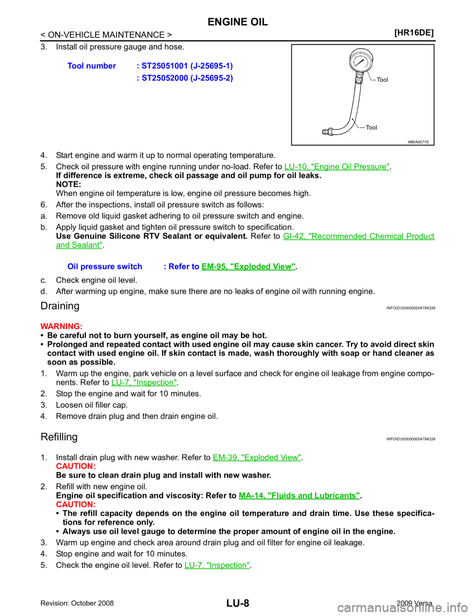
Tool number : ST25051001 (J-25695-1)
: ST25052000 (J-25695-2) Exploded View " .
Page 3765 of 4331
MA-22< SERVICE INFORMATION >
ENGINE MAINTENANCE (HR16DE)
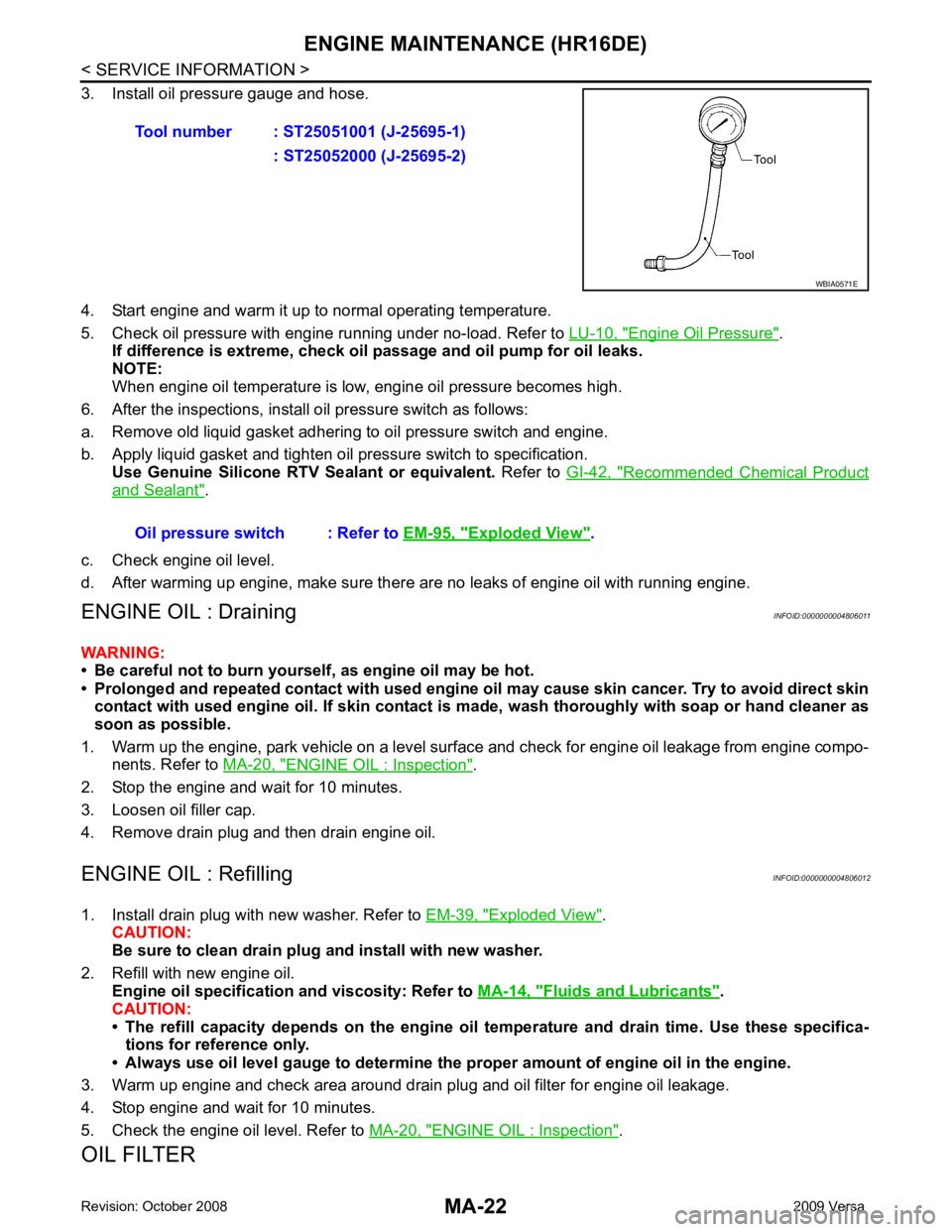
3. Install oil pressure gauge and hose.
4. Start engine and warm it up to normal operating temperature.
5. Check oil pressure with engine running under no-load. Refer to LU-10, " Engine Oil Pressure " .
If difference is extreme, check oil passage and oil pump for oil leaks.
NOTE:
When engine oil temperature is low, engine oil pressure becomes high.
6. After the inspections, install oil pressure switch as follows:
a. Remove old liquid gasket adhering to oil pressure switch and engine.
b. Apply liquid gasket and tighten oil pressure switch to specification. Use Genuine Silicone RTV Sealant or equivalent. Refer to GI-42, " Recommended Chemical Product
and Sealant " .
c. Check engine oil level.
d. After warming up engine, make sure there are no leaks of engine oil with running engine.
ENGINE OIL : Draining INFOID:0000000004806011
WARNING:
• Be careful not to burn yoursel f, as engine oil may be hot.
• Prolonged and repeated contact with used engine oil may cause ski n cancer. Try to avoid direct skin
contact with used engine oil. If skin contact is made, wash thoroughly with soap or hand cleaner as
soon as possible.
1. Warm up the engine, park vehicle on a level surface and check for engine oil leakage from engine compo- nents. Refer to MA-20, " ENGINE OIL : Inspection " .
2. Stop the engine and wait for 10 minutes.
3. Loosen oil filler cap.
4. Remove drain plug and then drain engine oil.
ENGINE OIL : Refilling INFOID:0000000004806012
1. Install drain plug with new washer. Refer to EM-39, " Exploded View " .
CAUTION:
Be sure to clean drain plug and install with new washer.
2. Refill with new engine oil. Engine oil specification and viscosity: Refer to MA-14, " Fluids and Lubricants " .
CAUTION:
• The refill capacity depends on the engine oi l temperature and drain time. Use these specifica-
tions for reference only.
• Always use oil level gauge to determine the pr oper amount of engine oil in the engine.
3. Warm up engine and check area around drain plug and oil filter for engine oil leakage.
4. Stop engine and wait for 10 minutes.
5. Check the engine oil level. Refer to MA-20, " ENGINE OIL : Inspection " .
OIL FILTER Tool number : ST25051001 (J-25695-1)
: ST25052000 (J-25695-2) WBIA0571E
Oil pressure switch : Refer to
EM-95, " Exploded View " .
Page 3810 of 4331
Removal and Installa-
tion " .
REMOVAL
1. Drain gear oil. Refer to MT-10, " Draining " (RS5F91R),
MT-52, " Changing M/T Oil " (RS6F94R).
2. Drain clutch fluid and remove clutch tube from CSC. Refer to CL-12, " Removal and Installation " .
CAUTION:
Do not depress clutch pedal during removal procedure.
3. Remove the engine and transaxle as an assembly from the vehicle. Refer to EM-88, " Removal and Instal-
lation " (HR16DE),
EM-195, " Removal and Installation " (MR18DE).
4. Remove the transaxle to engine and engine to transaxle bolts.
5. Separate the transaxle assembly from the engine.
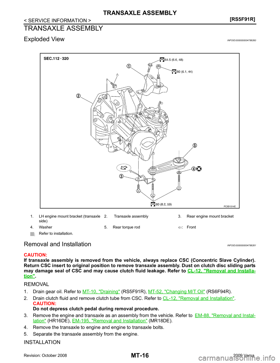
INSTALLATION 1. LH engine mount bracket (transaxle
side) 2. Transaxle assembly 3. Rear engine mount bracket
4. Washer 5. Rear torque rod ⇐: Front
: Refer to installation.
Page 3852 of 4331
Changing M/T Oil " .
2. Drain clutch fluid and remove clutch tube from CSC. Refer to CL-10, " Removal and Installation " .
CAUTION:
Do not depress clutch pedal during removal procedure.
3. Remove engine and transaxle assembly. Refer to EM-195, " Removal and Installation " .
4. Remove starter motor. Refer to SC-20, " Removal and Installation MR18DE " .
5. Remove transaxle assembly to engine bolts.
6. Separate transaxle assembly from engine.
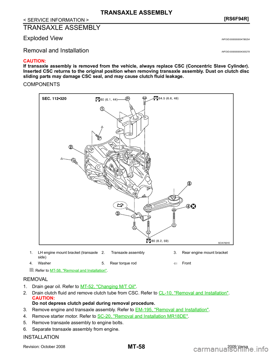
INSTALLATION 1. LH engine mount bracket (transaxle
side) 2. Transaxle assembly 3. Rear engine mount bracket
4. Washer 5. Rear torque rod ⇐Front
: Refer to MT-58, " Removal and Installation " .
Page 3972 of 4331
REFRIGERANT LINES
MTC-87
< SERVICE INFORMATION >
C
D E
F
G H
I
K L
M A
B MTC
N
O P
Moving the electronic leak detector probe slower
and closer to the suspected leak area will improve
the chances of finding a leak.
Checking System for Leaks Using the Fluorescent Leak Detector INFOID:0000000004307101
1. Check A/C system for leaks using the UV lamp and safety goggles J-42220 in a low sunlight area (area
without windows preferable). Illuminate all components, fittings and lines. The dye will appear as a bright
green/yellow area at the point of leakage. Fluoresc ent dye observed at the evaporator drain opening indi-
cates an evaporator core assembly (tubes , core or expansion valve) leak.
2. If the suspected area is difficult to see, use an adjustable mirror or wipe the area with a clean shop rag or
cloth, with the UV lamp for dye residue.
3. After the leak is repaired, remove any residual dye using dye cleaner J-43872 to prevent future misdiag- nosis.
4. Perform a system performance check and verify the leak repair with an approved electronic refrigerant leak detector.
NOTE:
Other gases in the work area or substances on the A/C components, for example, anti-freeze, windshield
washer fluid, solvents and oils, may falsely trigger the l eak detector. Make sure the surfaces to be checked are
clean.
Clean with a dry cloth or blow off with shop air.
Do not allow the sensor tip of the detector to contact with any substance. This can also cause false readings
and may damage the detector.
Dye Injection INFOID:0000000004307102
(This procedure is only necessary when recharging t he system or when the compressor has seized and was
replaced.)
1. Check A/C system static (at rest) pressure. Pres sure must be at least 345 kPa (3.45 bar, 3.52 kg/cm2
, 50
psi).
2. Pour one bottle (1/4 ounce / 7.4 cc) of the A/C refrigerant dye into the injector tool J-41459.
3. Connect the injector tool to the A/C low-pressure side service fitting.
4. Start engine and switch A/C ON.
5. When the A/C operating (compressor running), inject one bottle (1/4 ounce / 7.4 cc) of fluorescent dye
through the low-pressure service valve using dye inje ctor tool J-41459 (refer to the manufacture’s operat-
ing instructions).
6. With the engine still running, disconnect the injector tool from the service fitting.
CAUTION:
Be careful the A/C system or replacing a componen t, pour the dye directly into the open system
connection and proceed wi th the service procedures.
7. Operate the A/C system for a minimum of 20 minutes to mix the dye with the system oil. Depending on the
leak size, operating conditions and location of the leak , it may take from minutes to days for the dye to
penetrate a leak and become visible.
Electronic Refrigerant Leak Detector INFOID:0000000004307103
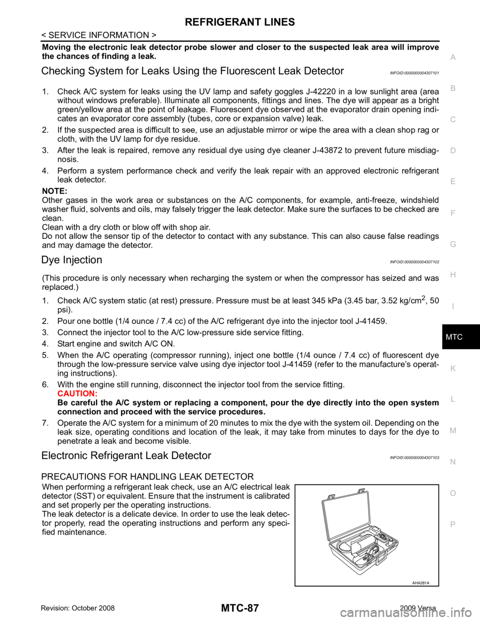
PRECAUTIONS FOR HANDLING LEAK DETECTOR When performing a refrigerant leak c heck, use an A/C electrical leak
detector (SST) or equivalent. Ensure that the instrument is calibrated
and set properly per the operating instructions.
The leak detector is a delicate device. In order to use the leak detec-
tor properly, read the operating instructions and perform any speci-
fied maintenance. AHA281A
Page 4311 of 4331
WW
N
O P
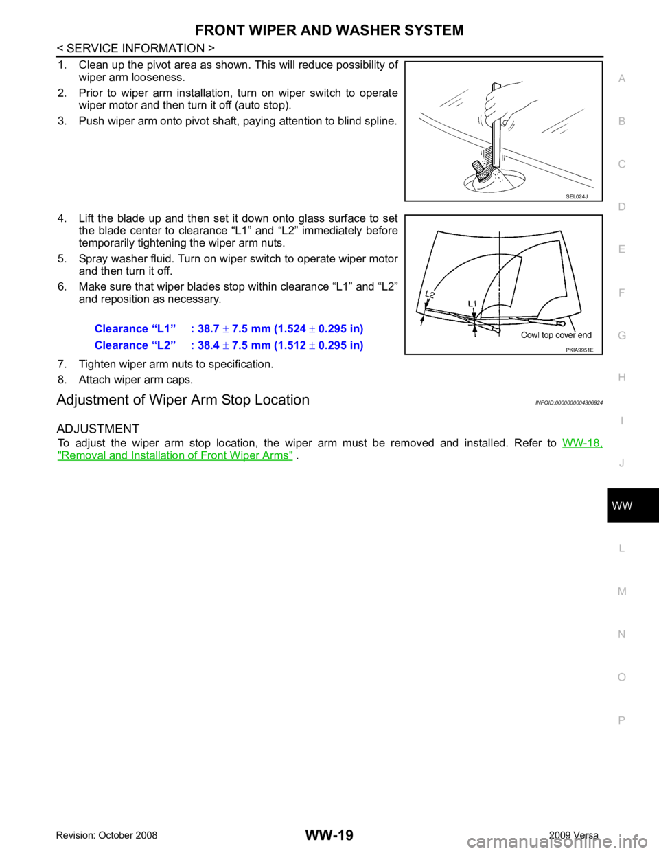
1. Clean up the pivot area as shown. This will reduce possibility of
wiper arm looseness.
2. Prior to wiper arm installation, turn on wiper switch to operate wiper motor and then turn it off (auto stop).
3. Push wiper arm onto pivot shaft, paying attention to blind spline.
4. Lift the blade up and then set it down onto glass surface to set the blade center to clearance “L1” and “L2” immediately before
temporarily tightening the wiper arm nuts.
5. Spray washer fluid. Turn on wiper switch to operate wiper motor and then turn it off.
6. Make sure that wiper blades stop within clearance “L1” and “L2” and reposition as necessary.
7. Tighten wiper arm nuts to specification.
8. Attach wiper arm caps.
Adjustment of Wiper Arm Stop Location INFOID:0000000004306924
ADJUSTMENT To adjust the wiper arm stop location, the wiper arm must be removed and installed. Refer to WW-18," Removal and Installation of Front Wiper Arms " .
Page 4315 of 4331
WW
N
O P
Removal and Installation of
Front Wiper and Washer Switch INFOID:0000000004306930
REMOVAL 1. Remove the steering column cover. Refer to IP-11 .
2. Disconnect the wiper and washer switch connector.
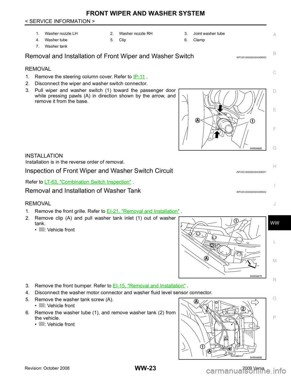
3. Pull wiper and washer switch (1) toward the passenger door while pressing pawls (A) in direction shown by the arrow, and
remove it from the base.
INSTALLATION Installation is in the reverse order of removal.
Inspection of Front Wiper and Washer Switch Circuit INFOID:0000000004306931
Refer to LT-63, " Combination Switch Inspection " .
Removal and Installation of Washer Tank INFOID:0000000004306932
REMOVAL 1. Remove the front grille. Refer to EI-21, " Removal and Installation " .
2. Remove clip (A) and pull washer tank inlet (1) out of washer tank.
• : Vehicle front
3. Remove the front bumper. Refer to EI-15, " Removal and Installation " .
4. Disconnect the washer motor connector and washer fluid level sensor connector.
5. Remove the washer tank screw (A). • : Vehicle front
6. Remove the washer tube (1), and remove washer tank (2) from the vehicle.
• : Vehicle front 1. Washer nozzle LH 2. Washer nozzle RH 3. Joint washer tube
4. Washer tube 5. Clip 6. Clamp
7. Washer tank