battery NISSAN TIIDA 2009 Service Owner's Manual
[x] Cancel search | Manufacturer: NISSAN, Model Year: 2009, Model line: TIIDA, Model: NISSAN TIIDA 2009Pages: 4331, PDF Size: 58.04 MB
Page 158 of 4331
AT
N
O P
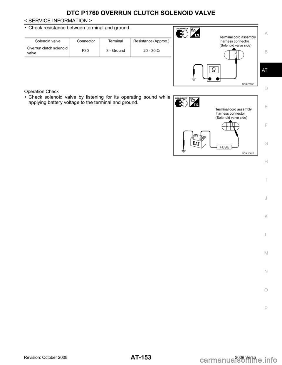
• Check resistance between terminal and ground.
Operation Check • Check solenoid valve by listening for its operating sound while applying battery voltage to the terminal and ground. Solenoid valve Connector Terminal Resistance (Approx.)
Overrun clutch solenoid
valve F30 3 - Ground 20 - 30
Ω
Page 170 of 4331
AT
N
O P
Diagnosis Procedure
INFOID:0000000004305456OK >> GO TO 8.
NG >> GO TO 2. Wiring Diagram - AT - MAIN " and
AT-164, " Wiring Diagram - AT -
PT/SEN " .
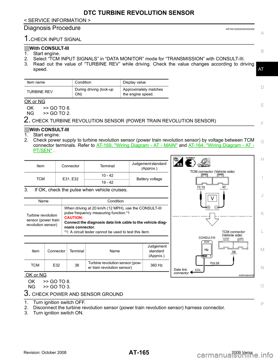
3. If OK, check the pulse when vehicle cruises.
OK or NG OK >> GO TO 8.
NG >> GO TO 3. Item Connector Terminal
Judgement standard
(Approx.)
TCM E31, E32 10 - 42
Battery voltage
19 - 42
Name Condition
Turbine revolution
sensor (power train
revolution sensor) When driving at 20 km/h (12 MPH), use the CONSULT-III
pulse frequency measuring function.*1
CAUTION:
Connect the diagnosis data link cable to the vehicle diag-
nosis connector.
*1: A circuit tester cannot be used to test this item.
Item Connector Terminal Name Judgement
standard
(Approx.)
TCM E32 38 Turbine revolution sensor (pow-
er train revolution sensor) 360 Hz B
Page 171 of 4331
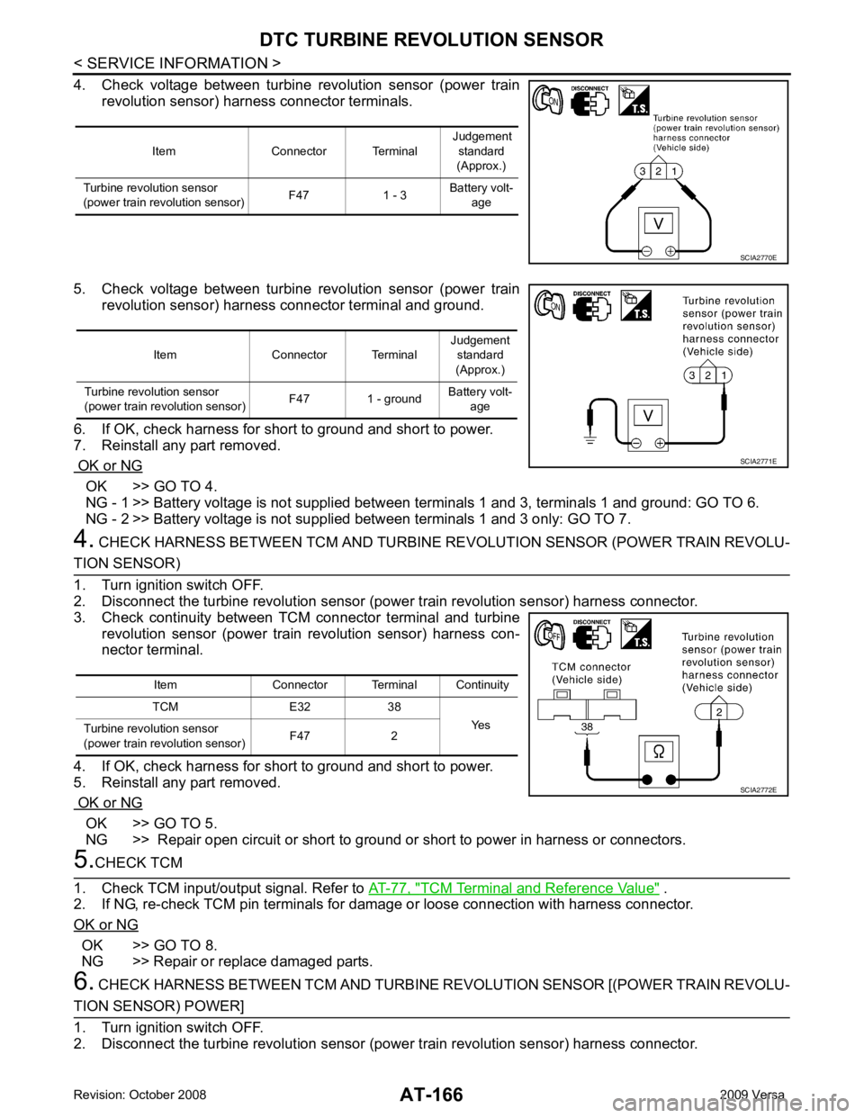
OK >> GO TO 4.
NG - 1 >> Battery voltage is not supplied betw een terminals 1 and 3, terminals 1 and ground: GO TO 6.
NG - 2 >> Battery voltage is not supp lied between terminals 1 and 3 only: GO TO 7.
4. CHECK HARNESS BETWEEN TCM AND TURBINE RE VOLUTION SENSOR (POWER TRAIN REVOLU- OK >> GO TO 5.
NG >> Repair open circuit or short to ground or short to power in harness or connectors. TCM Terminal and Reference Value " .
2. If NG, re-check TCM pin terminals for damage or loose connection with harness connector.
OK or NG OK >> GO TO 8.
NG >> Repair or replace damaged parts.
6. CHECK HARNESS BETWEEN TCM AND TURBINE REVOLUTION SENSOR [(POWER TRAIN REVOLU-
Page 175 of 4331
AT-170< SERVICE INFORMATION >
MAIN POWER SUPPLY AND GROUND CIRCUIT
Diagnosis Procedure INFOID:00000000043054631.
CHECK TCM POWER SOURCE
1. Turn ignition switch ON. (Do not start engine.)
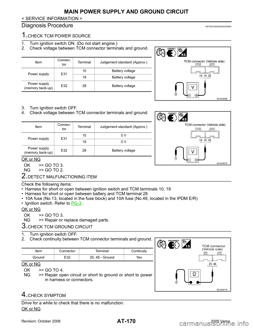
2. Check voltage between TCM connector terminals and ground.
3. Turn ignition switch OFF.
4. Check voltage between TCM connector terminals and ground.
OK or NG OK >> GO TO 3.
NG >> GO TO 2. 2.
DETECT MALFUNCTIONING ITEM
Check the following items:
• Harness for short or open between ignition switch and TCM terminals 10, 19
• Harness for short or open between battery and TCM terminal 28
• 10A fuse (No.13, located in the fuse block) and 10A fuse (No.49, located in the IPDM E/R)
• Ignition switch. Refer to PG-3 .
OK or NG OK >> GO TO 3.
NG >> Repair or replace damaged parts. 3.
CHECK TCM GROUND CIRCUIT
1. Turn ignition switch OFF.
2. Check continuity between TCM connector terminals and ground.
OK or NG OK >> GO TO 4.
NG >> Repair open circuit or short to ground or short to power in harness or connectors. 4.
CHECK SYMPTOM
Drive for a while to check that there is no malfunction.
OK or NG Item
Connec-
tor Terminal Judgement standard (Approx.)
Power supply E31 10 Battery voltage
19 Battery voltage
Power supply
(memory back-up) E32 28 Battery voltage SCIA2656E
Item
Connec-
tor Terminal Judgement standard (Approx.)
Power supply E31 10 0 V
19 0 V
Power supply
(memory back-up) E32 28 Battery voltage SCIA2657E
Item Connector Terminal Continuity
Ground E32 25, 48 - Ground Yes SCIA2671E
Page 177 of 4331

CONSULT-III Function (TRANSMISSION) " .
Is a malfunction in the CAN communication indicated in the results? YES >> Check CAN communication line. Refer to
AT-88 .
NO (With CONSULT-III) >>GO TO 2.
NO (Without CONSULT-III) >>GO TO 3. Item name Condition Display value
PN POSI SW When setting selector lever
to “N” or “P” position. ON
When setting selector lever to other positions. OFF
R POSITION SW When setting selector lever to “R” position. ON
When setting selector lever to other positions. OFF
D POSITION SW When setting selector lever to “D” position. ON
When setting selector lever to other positions. OFF
2 POSITION SW When setting selector lever to “2” position. ON
When setting selector lever to other positions. OFF
1 POSITION SW When setting selector lever to “1” position. ON
When setting selector lever to other positions. OFF
OVERDRIVE SW When overdrive control switch is depressed. ON
When overdrive control switch is released. OFF
CLOSED THL/SW Released accelerator pedal. ON
Depressed accelerator pedal. OFF
W/O THRL/P-SW Fully depressed accelerator pedal. ON
Released accelerator pedal. OFF Terminal Wire color Item Condition
Judgement standard
(Approx.)
26 Y PNP switch “1” posi-
tion
andWhen setting selector lever to “1” position. Battery voltage
When setting selector lever to other positions. 0 V
27 G PNP switch “2” posi-
tion When setting selector lever to “2” position. Battery voltage
When setting selector lever to other positions. 0 V
34 LG PNP switch “D” posi-
tion When setting selector lever to “D” position. Battery voltage
When setting selector lever to other positions. 0 V
35 SB PNP switch “R” posi-
tion When setting selector lever to “R” position. Battery voltage
When setting selector lever to other positions. 0 V
36 R PNP switch “N” or “P”
position When setting selector le
ver to “N” or “P” posi-
tions. Battery voltage
When setting selector lever to other positions. 0 V
Page 178 of 4331
PNP, OD SWITCH AND CLOSED THRO
TTLE, WIDE OPEN THROTTLE POSI-
TION SIGNAL CIRCUIT
AT-173
< SERVICE INFORMATION >
D
E
F
G H
I
J
K L
M A
B AT
N
O P 2.
CHECK PNP SWITCH CIRCUIT
With CONSULT-III
1. Turn ignition switch ON. (Do not start engine.)
2. Select “TCM INPUT SIGNALS” in “DATA MONI TOR” mode for “TRANSMISSION” with CONSULT-III.
3. Read out “P·N”, “R”, “D”, “2” and “1” position switches moving selector lever to each position.
OK or NG OK >> GO TO 4.
NG >> Check PNP switch circuit. Refer to AT-91 .
3.
CHECK PNP SWITCH CIRCUIT
Without CONSULT-III
1. Turn ignition switch ON. (Do not start engine.)
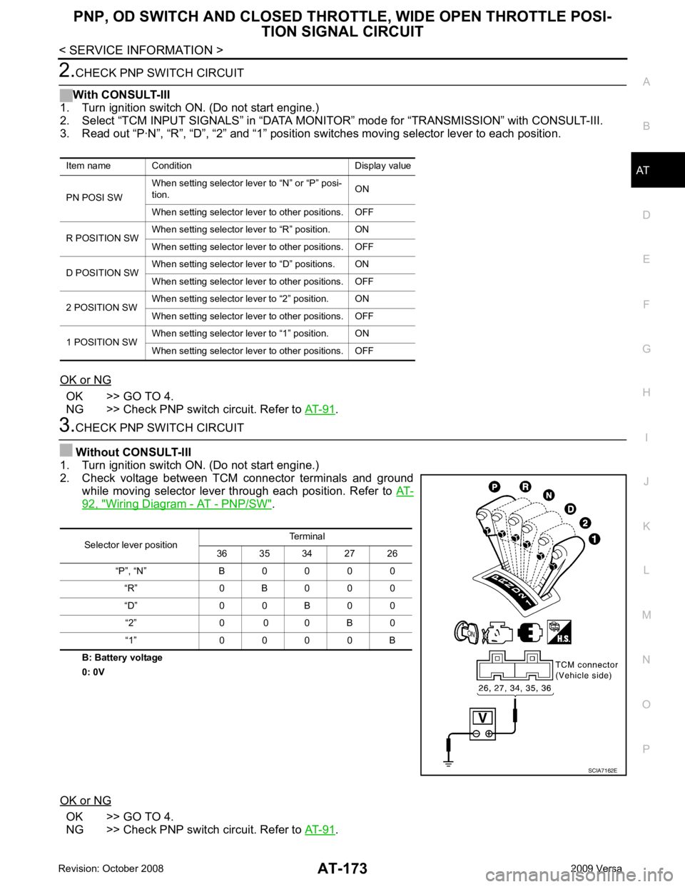
2. Check voltage between TCM connector terminals and ground while moving selector lever through each position. Refer to AT-92, " Wiring Diagram - AT - PNP/SW " .
B: Battery voltage
0: 0V
OK or NG OK >> GO TO 4.
NG >> Check PNP switch circuit. Refer to AT-91 .
Item name Condition Display value
PN POSI SW When setting selector le
ver to “N” or “P” posi-
tion. ON
When setting selector lever to other positions. OFF
R POSITION SW When setting selector lever to “R” position. ON
When setting selector lever to other positions. OFF
D POSITION SW When setting selector lever to “D” positions. ON
When setting selector lever to other positions. OFF
2 POSITION SW When setting selector lever to “2” position. ON
When setting selector lever to other positions. OFF
1 POSITION SW When setting selector lever to “1” position. ON
When setting selector lever to other positions. OFF Selector lever position
Terminal
36 35 34 27 26
“P”, “N” B 0 0 0 0 “R” 0 B 0 0 0
“D” 0 0 B 0 0 “2” 0 0 0 B 0
“1” 0 0 0 0 B SCIA7162E
Page 180 of 4331
AT
N
O P
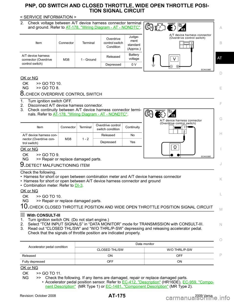
2. Check voltage between A/T device harness connector terminal
and ground. Refer to AT-178, " Wiring Diagram - AT - NONDTC " .
OK or NG OK >> GO TO 10.
NG >> GO TO 8. Wiring Diagram - AT - NONDTC " .
OK or NG OK >> GO TO 9.
NG >> Repair or replace damaged parts. .
OK or NG OK >> GO TO 10.
NG >> Repair or replace damaged parts. OK >> GO TO 11.
NG >> Check the following. If any items are damaged, repair or replace damaged parts. • Accelerator pedal position sensor. Refer to EC-412, " Description " (HR16DE),
EC-959, " Compo-
nent Description " (MR Type 1) or
EC-1481, " Component Description " (MR Type 2).
Item Connector Terminal
Overdrive
control switch Condition Judge-
ment
standard
(Approx.)
A/T device harness
connector (Overdrive
control switch) M38 1 - Ground
Released
Battery
voltage
Depressed 0 V
Page 187 of 4331
AT-182< SERVICE INFORMATION >
TROUBLE DIAGNOSIS FOR SYMPTOMS
OD OFF indicator lamp does not come on for about 2 seconds when turning ignition switch to ON.
DIAGNOSTIC PROCEDURE 1.
CHECK CAN COMMUNICATION LINE
Perform self-diagnosis. Refer to AT-79, " CONSULT-III Function (TRANSMISSION) " .
Is a malfunction in CAN communication indicated in the results? YES >> Check CAN communication line. Refer to
AT-88 .
NO >> GO TO 2. 2.
CHECK TCM POWER SOURCE
1. Turn ignition switch ON. (Do not start engine.)
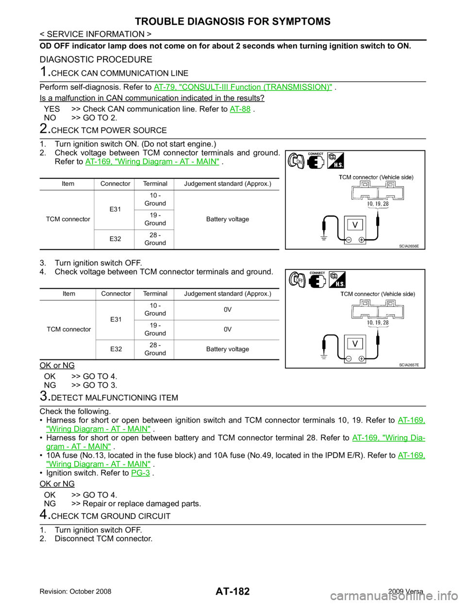
2. Check voltage between TCM connector terminals and ground.
Refer to AT-169, " Wiring Diagram - AT - MAIN " .
3. Turn ignition switch OFF.
4. Check voltage between TCM connector terminals and ground.
OK or NG OK >> GO TO 4.
NG >> GO TO 3. 3.
DETECT MALFUNCTIONING ITEM
Check the following.
• Harness for short or open between ignition switch and TCM connector terminals 10, 19. Refer to AT-169," Wiring Diagram - AT - MAIN " .
• Harness for short or open between battery and TCM connector terminal 28. Refer to AT-169, " Wiring Dia-
gram - AT - MAIN " .
• 10A fuse (No.13, located in the fuse block) and 10A fuse (No.49, located in the IPDM E/R). Refer to AT-169," Wiring Diagram - AT - MAIN " .
• Ignition switch. Refer to PG-3 .
OK or NG OK >> GO TO 4.
NG >> Repair or replace damaged parts. 4.
CHECK TCM GROUND CIRCUIT
1. Turn ignition switch OFF.
2. Disconnect TCM connector. Item Connector Terminal Judgement standard (Approx.)
TCM connector E3110 -
Ground
Battery voltage
19 -
Ground
E32 28 -
Ground SCIA2656E
Item Connector Terminal Judgement standard (Approx.)
TCM connector E3110 -
Ground 0V
19 -
Ground 0V
E32 28 -
Ground Battery voltage SCIA2657E
Page 204 of 4331
TROUBLE DIAGNOSIS FOR SYMPTOMS
AT-199
< SERVICE INFORMATION >
D
E
F
G H
I
J
K L
M A
B AT
N
O P
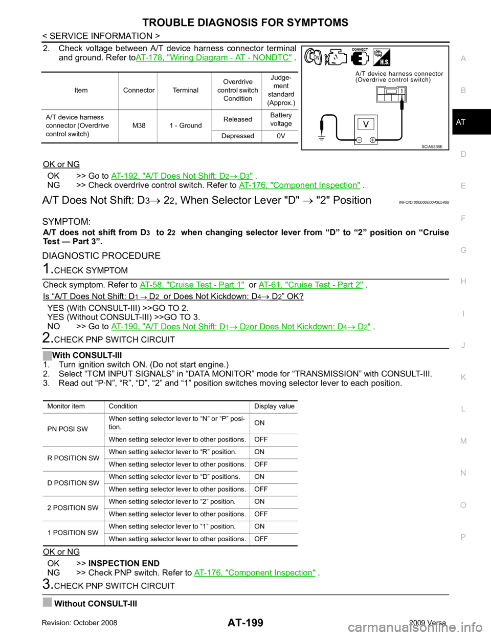
2. Check voltage between A/T device harness connector terminal
and ground. Refer to AT-178, " Wiring Diagram - AT - NONDTC " .
OK or NG OK >> Go to
AT-192, " A/T Does Not Shift: D 2 → D 3 " .
NG >> Check overdrive control switch. Refer to AT-176, " Component Inspection " .
A/T Does Not Shift: D 3→ 22, When Selector Lever "D" → "2" Position INFOID:0000000004305488
SYMPTOM: A/T does not shift from D 3 to 2 2 when changing selector lever from “D” to “2” position on “Cruise
Test — Part 3”.
DIAGNOSTIC PROCEDURE 1.
CHECK SYMPTOM
Check symptom. Refer to AT-58, " Cruise Test - Part 1 " or
AT-61, " Cruise Test - Part 2 " .
Is “ A/T Does Not Shift: D 1 → D 2 or Does Not Kickdown: D 4 → D 2 ” OK?
YES (With CONSULT-III) >>GO TO 2.
YES (Without CONSULT-III) >>GO TO 3.
NO >> Go to AT-190, " A/T Does Not Shift: D 1 → D 2 or Does Not Kickdown: D 4 → D 2 " .
2.
CHECK PNP SWITCH CIRCUIT
With CONSULT-III
1. Turn ignition switch ON. (Do not start engine.)
2. Select “TCM INPUT SIGNALS” in “DATA MONI TOR” mode for “TRANSMISSION” with CONSULT-III.
3. Read out “P·N”, “R”, “D”, “2” and “1” position switches moving selector lever to each position.
OK or NG OK >>
INSPECTION END
NG >> Check PNP switch. Refer to AT-176, " Component Inspection " .
3.
CHECK PNP SWITCH CIRCUIT
Without CONSULT-III Item Connector Terminal
Overdrive
control switch Condition Judge-
ment
standard
(Approx.)
A/T device harness
connector (Overdrive
control switch) M38 1 - Ground
Released
Battery
voltage
Depressed 0V SCIA5336E
Monitor item Condition Display value
PN POSI SW When setting selector le
ver to “N” or “P” posi-
tion. ON
When setting selector lever to other positions. OFF
R POSITION SW When setting selector lever to “R” position. ON
When setting selector lever to other positions. OFF
D POSITION SW When setting selector lever to “D” positions. ON
When setting selector lever to other positions. OFF
2 POSITION SW When setting selector lever to “2” position. ON
When setting selector lever to other positions. OFF
1 POSITION SW When setting selector lever to “1” position. ON
When setting selector lever to other positions. OFF
Page 205 of 4331
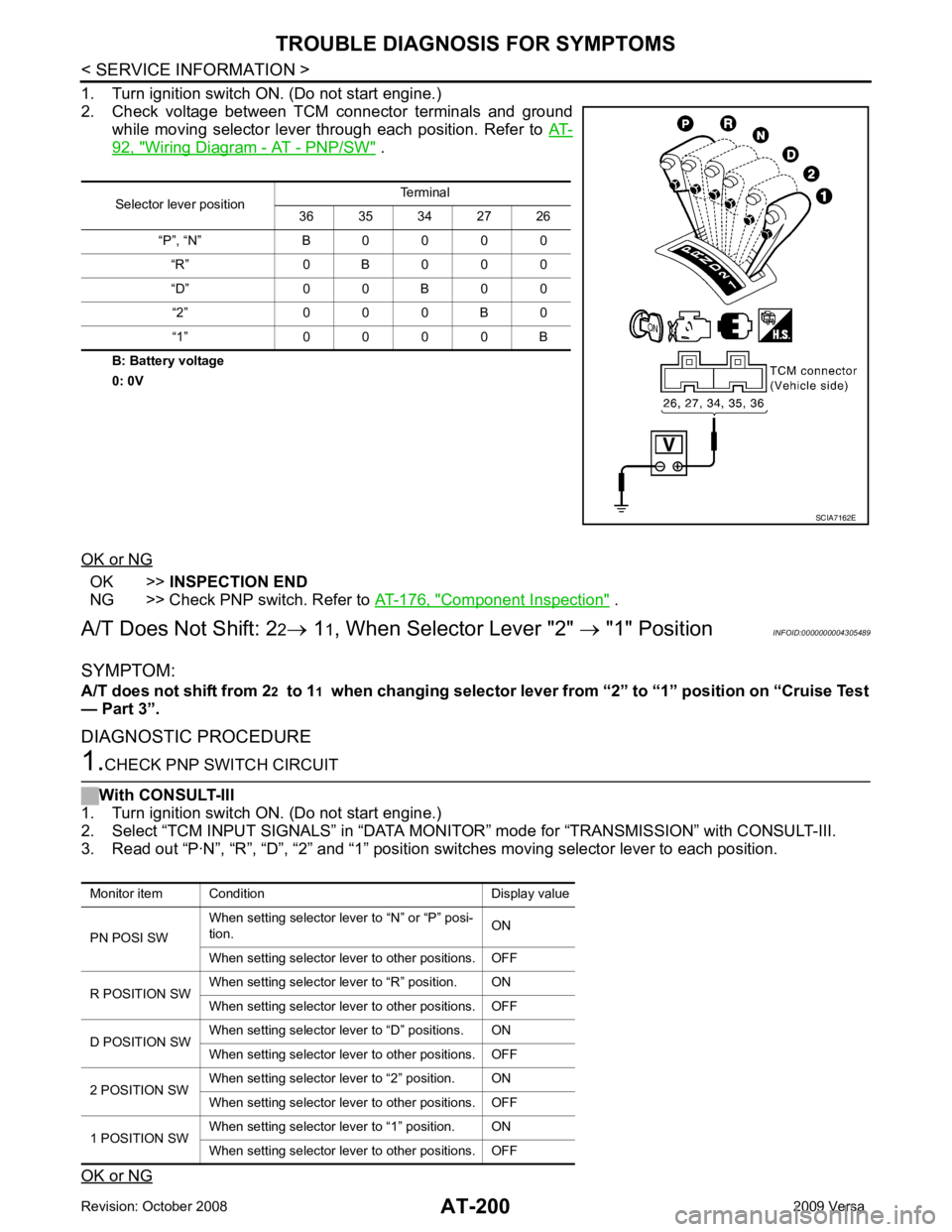
AT-200< SERVICE INFORMATION >
TROUBLE DIAGNOSIS FOR SYMPTOMS
1. Turn ignition switch ON. (Do not start engine.)
2. Check voltage between TCM connector terminals and ground while moving selector lever through each position. Refer to AT-92, " Wiring Diagram - AT - PNP/SW " .
B: Battery voltage
0: 0V
OK or NG OK >>
INSPECTION END
NG >> Check PNP switch. Refer to AT-176, " Component Inspection " .
A/T Does Not Shift: 2 2→ 11, When Selector Lever "2" → "1" Position INFOID:0000000004305489
SYMPTOM:
A/T does not shift from 2 2 to 1 1 when changing selector lever from “2” to “1” position on “Cruise Test
— Part 3”.
DIAGNOSTIC PROCEDURE 1.
CHECK PNP SWITCH CIRCUIT
With CONSULT-III
1. Turn ignition switch ON. (Do not start engine.)
2. Select “TCM INPUT SIGNALS” in “DATA MONITO R” mode for “TRANSMISSION” with CONSULT-III.
3. Read out “P·N”, “R”, “D”, “2” and “1” position switches moving selector lever to each position.
OK or NG Selector lever position
Terminal
36 35 34 27 26
“P”, “N” B 0 0 0 0 “R” 0 B 0 0 0
“D” 0 0 B 0 0 “2” 0 0 0 B 0
“1” 0 0 0 0 B SCIA7162E
Monitor item Condition Display value
PN POSI SW When setting selector le
ver to “N” or “P” posi-
tion. ON
When setting selector lever to other positions. OFF
R POSITION SW When setting selector lever to “R” position. ON
When setting selector lever to other positions. OFF
D POSITION SW When setting selector lever to “D” positions. ON
When setting selector lever to other positions. OFF
2 POSITION SW When setting selector lever to “2” position. ON
When setting selector lever to other positions. OFF
1 POSITION SW When setting selector lever to “1” position. ON
When setting selector lever to other positions. OFF