belt NISSAN TIIDA 2009 Service Owner's Manual
[x] Cancel search | Manufacturer: NISSAN, Model Year: 2009, Model line: TIIDA, Model: NISSAN TIIDA 2009Pages: 4331, PDF Size: 58.04 MB
Page 916 of 4331
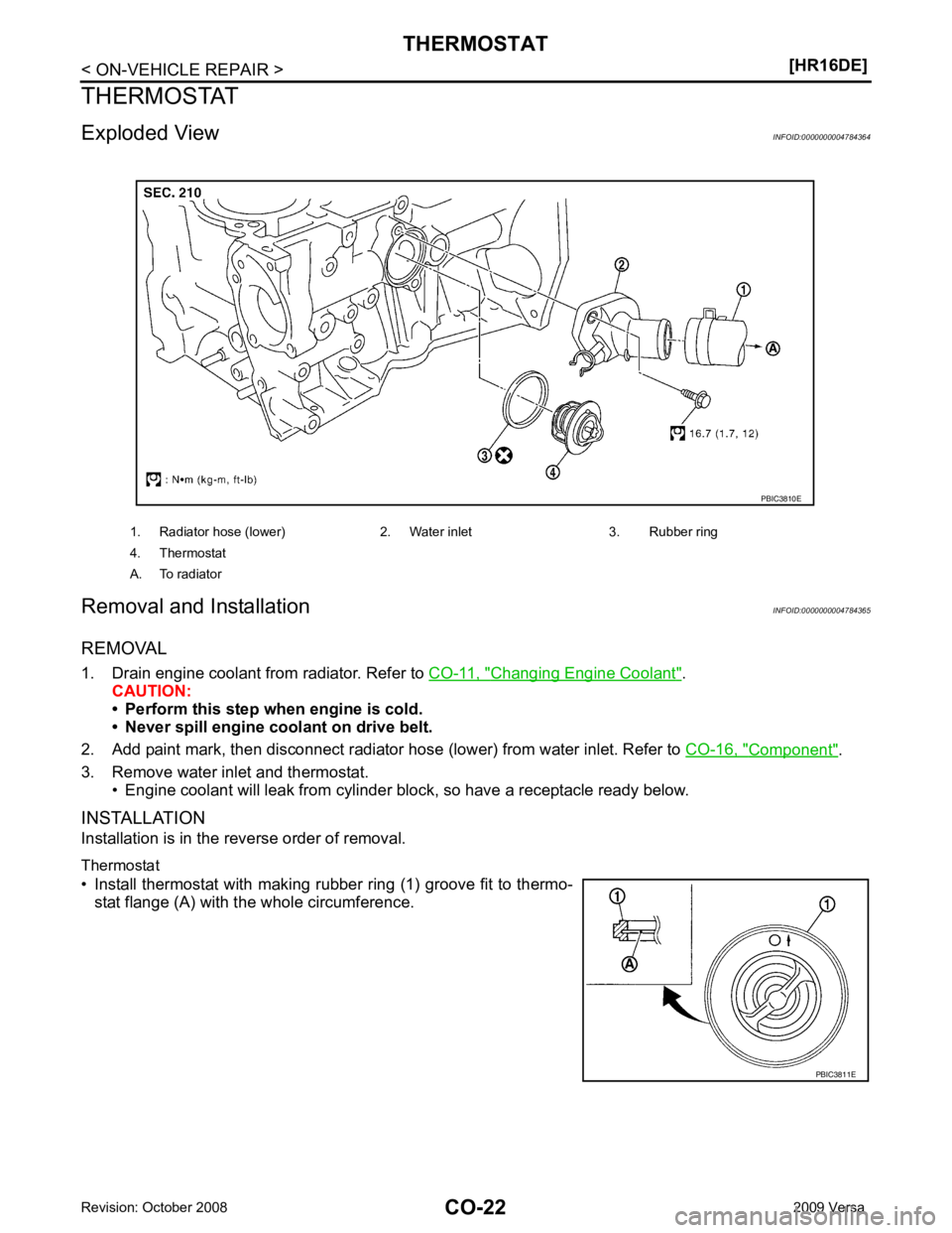
Changing Engine Coolant " .
CAUTION:
• Perform this step when engine is cold.
• Never spill engine coolant on drive belt.
2. Add paint mark, then disconnect radiator hose (lower) from water inlet. Refer to CO-16, " Component " .
3. Remove water inlet and thermostat. • Engine coolant will leak from cylinder block, so have a receptacle ready below.
INSTALLATION
Installation is in the reverse order of removal.
Thermostat
• Install thermostat with making rubber ring (1) groove fit to thermo- stat flange (A) with the whole circumference. 1. Radiator hose (lower) 2. Water inlet 3. Rubber ring
4. Thermostat
A. To radiator PBIC3811E
Page 918 of 4331
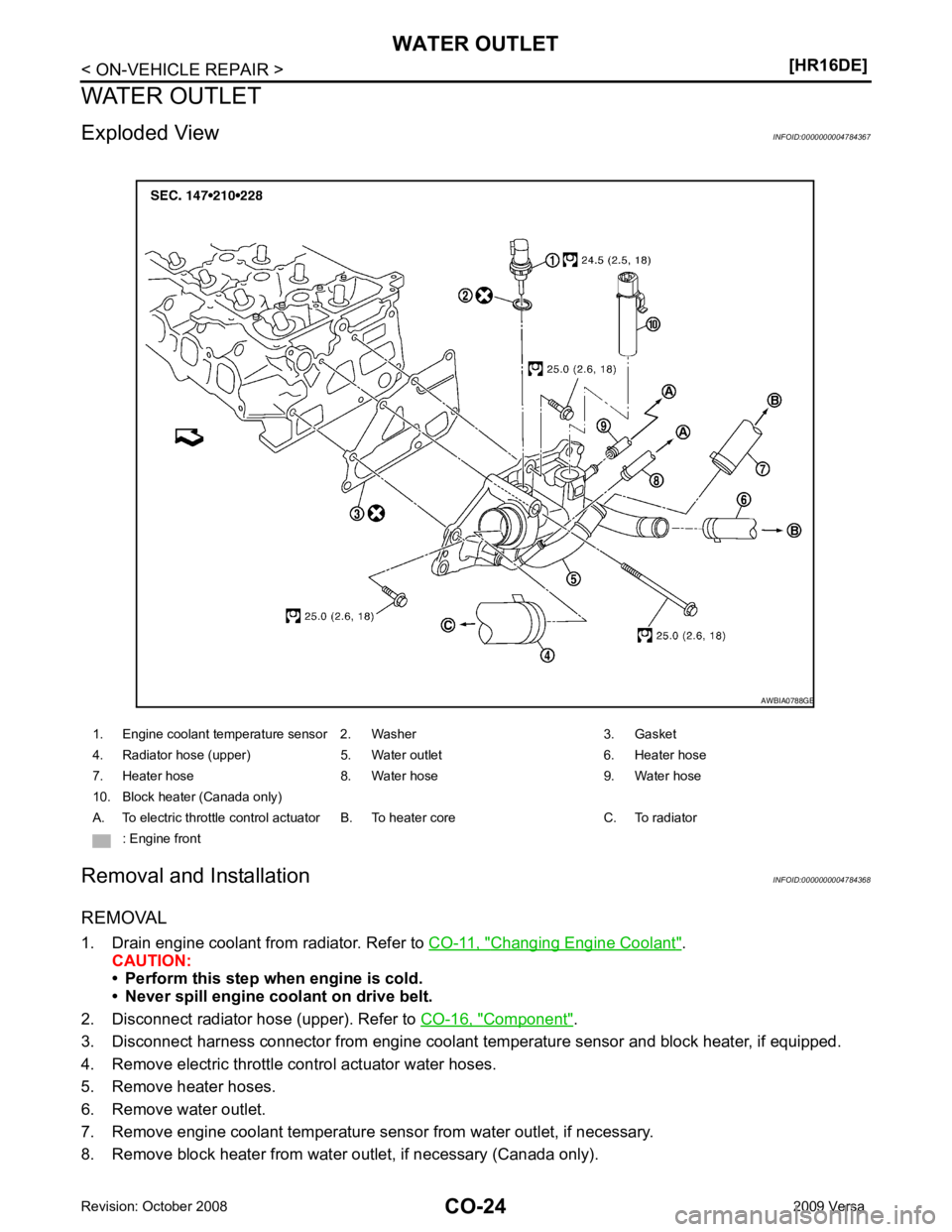
Changing Engine Coolant " .
CAUTION:
• Perform this step when engine is cold.
• Never spill engine coolant on drive belt.
2. Disconnect radiator hose (upper). Refer to CO-16, " Component " .
3. Disconnect harness connector from engine coolant temperature sensor and block heater, if equipped.
4. Remove electric throttle control actuator water hoses.
5. Remove heater hoses.
6. Remove water outlet.
7. Remove engine coolant temperature sens or from water outlet, if necessary.
8. Remove block heater from water outlet, if necessary (Canada only). 1. Engine coolant temperature sensor 2. Washer 3. Gasket
4. Radiator hose (upper) 5. Water outlet 6. Heater hose
7. Heater hose 8. Water hose 9. Water hose
10. Block heater (Canada only)
A. To electric throttle control actuator B. To heater core C. To radiator : Engine front
Page 929 of 4331
![NISSAN TIIDA 2009 Service Owners Manual ENGINE COOLANT
CO-35
< SERVICE INFORMATION >
[MR18DE] C
D E
F
G H
I
J
K L
M A CO
NP
O
ENGINE COOLANT
Inspection INFOID:0000000004305234
LEVEL CHECK • Check if the reservoir tank engine coolant level](/img/5/57398/w960_57398-928.png "NISSAN TIIDA 2009 Service Owners Manual ENGINE COOLANT
CO-35
< SERVICE INFORMATION >
[MR18DE] C
D E
F
G H
I
J
K L
M A CO
NP
O
ENGINE COOLANT
Inspection INFOID:0000000004305234
LEVEL CHECK • Check if the reservoir tank engine coolant level")
ENGINE COOLANT
CO-35
< SERVICE INFORMATION >
[MR18DE] C
D E
F
G H
I
J
K L
M A CO
NP
O
ENGINE COOLANT
Inspection INFOID:0000000004305234
LEVEL CHECK • Check if the reservoir tank engine coolant level is within the “MIN” to “MAX” range when engine is cool.
• Adjust the engine coolant level as necessary.
CHECKING COOLING SYSTEM FOR LEAKS To check for leaks, apply pressure to the cooling system using suit-
able tool and Tool.
WARNING:
Never remove the radiator cap wh en the engine is hot. Serious
burns could occur from high pressure coolant escaping from
the radiator.
CAUTION:
Higher pressure than specified may cause radiator damage.
Changing Engine Coolant INFOID:0000000004673021
WARNING:
• To avoid being scalded, do not change engine coolant when engine is hot.
• Wrap a thick cloth around radiator cap and carefully remove the cap. First, turn the cap a quarter of a
turn to release built-up pressure. Then turn the cap all the way.
CAUTION:
• Do not spill engine coolant on drive belt.
DRAINING ENGINE COOLANT 1. Open radiator drain plug (1) at the bottom of radiator, and then remove radiator cap.
• Front
When draining all of engine coolant in the system, open
water drain plug on cylinder block. Refer to EM-200 .
CAUTION:
• Perform this step when engine is cold.
• Do not spill engine coolant on drive belt.
2. Remove reservoir tank as necessary, and drain engi ne coolant and clean reservoir tank before installing.
Refer to CO-38, " Component " .
3. Check drained engine coolant for contaminants such as rust, corrosion or discoloration. If contaminated, flush the engine cooling system. SMA412B
Tool number : EG17650301 (J-33984-A)
Testing pressure : 157 kPa (1.6 kg/cm 2
, 23 psi) WBIA0568E
PBIC3799E
Page 933 of 4331
![NISSAN TIIDA 2009 Service Owners Manual RADIATOR
CO-39
< SERVICE INFORMATION >
[MR18DE] C
D E
F
G H
I
J
K L
M A CO
NP
O
Do not remove radiator cap when the engine is
hot. Serious burns could occur from high-pressure
engine c](/img/5/57398/w960_57398-932.png "NISSAN TIIDA 2009 Service Owners Manual RADIATOR
CO-39
< SERVICE INFORMATION >
[MR18DE] C
D E
F
G H
I
J
K L
M A CO
NP
O
Do not remove radiator cap when the engine is
hot. Serious burns could occur from high-pressure
engine c")
RADIATOR
CO-39
< SERVICE INFORMATION >
[MR18DE] C
D E
F
G H
I
J
K L
M A CO
NP
O
Do not remove radiator cap when the engine is
hot. Serious burns could occur from high-pressure
engine coolant escaping from radiator. Wrap a thick cl oth around the cap. Slowly turn it a quarter of a
turn to release built-up pressure. Carefully remove radiator cap by turning it all the way.
REMOVAL 1. Drain engine coolant from radiator. Refer to CO-35, " Changing Engine Coolant " .
CAUTION:
• Perform this step when engine is cold.
• Do not spill engine coolant on drive belt.
2. Remove engine undercover.
3. Remove air duct (inlet). Refer to EM-139 .
4. Remove reservoir tank as follows:
a. Disconnect reservoir tank hose.
b. Release the tab (A) in the direction shown by the arrow ( ).
c. Lift up while removing the reservoir tank hose, and remove it.
5. Disconnect harness connector from fan motor, and move harness aside.
6. Disconnect CVT or A/T fluid cooler hoses if equipped. • Install plug to avoid leakage of CVT or A/T fluid if equipped.
7. Remove radiator hoses (upper and lower).
8. Remove radiator core support cover. Refer to BL-19 .
9. Remove radiator core support (upper) bolts, bolts of stationary part on the radiator core support side and clip. Lift radiator from
radiator (upper) mount part of radiator core support (upper) (2).
10. Move radiator assembly (1) to the rearward direction of vehicle, and then lift it upward to remove.
CAUTION:
Do not damage or scratch A/C condenser if equipped and
radiator core when removing.
INSTALLATION Installation is in the reverse order of removal.
CAUTION:
Do not damage or scratch A/C condenser if eq uipped and radiator core when installing.
INSPECTION AFTER INSTALLATION • Check for leaks of engine coolant. Refer to CO-35, " Inspection " .
• Start and warm up engine. Visually check for leaks of engine coolant and CVT or A/T fluid if equipped. Refer
to CVT-196 or
AT-17 . PBIC3800E
PBIC3805E
Page 936 of 4331
Changing Engine Coolant " .
CAUTION:
• Perform this step when engine is cold.
• Do not spill engine coolant on drive belt.
2. Remove air duct (inlet). Refer to EM-139, " Component " .
3. Remove reservoir tank. Refer to CO-38, " Component " .
4. Disconnect radiator hose (upper) at radiator side. Refer to CO-38, " Component " .
5. Disconnect harness connectors from fan motor, and move harness aside.
6. Remove cooling fan assembly. CAUTION:
Be careful not to damage or scratch the radiator core.
INSTALLATION
Installation is in the reverse order of removal.
• Cooling fans are controlled by ECM. For details, refer to EC-886, " System Description " .
CAUTION:
Be careful not to damage or scratch the radiator core.
Disassembly and Assembly INFOID:0000000004305243
DISASSEMBLY
1. Remove cooling fan from fan motor.
2. Remove fan motor from fan shroud.
INSPECTION AFTER DISASSEMBLY
Inspect cooling fan for crack or unusual bend.
• If anything is found, replace cooling fan.
ASSEMBLY
Assembly is in the reverse order of disassembly.
Page 937 of 4331
CO
NP
O
WATER PUMP
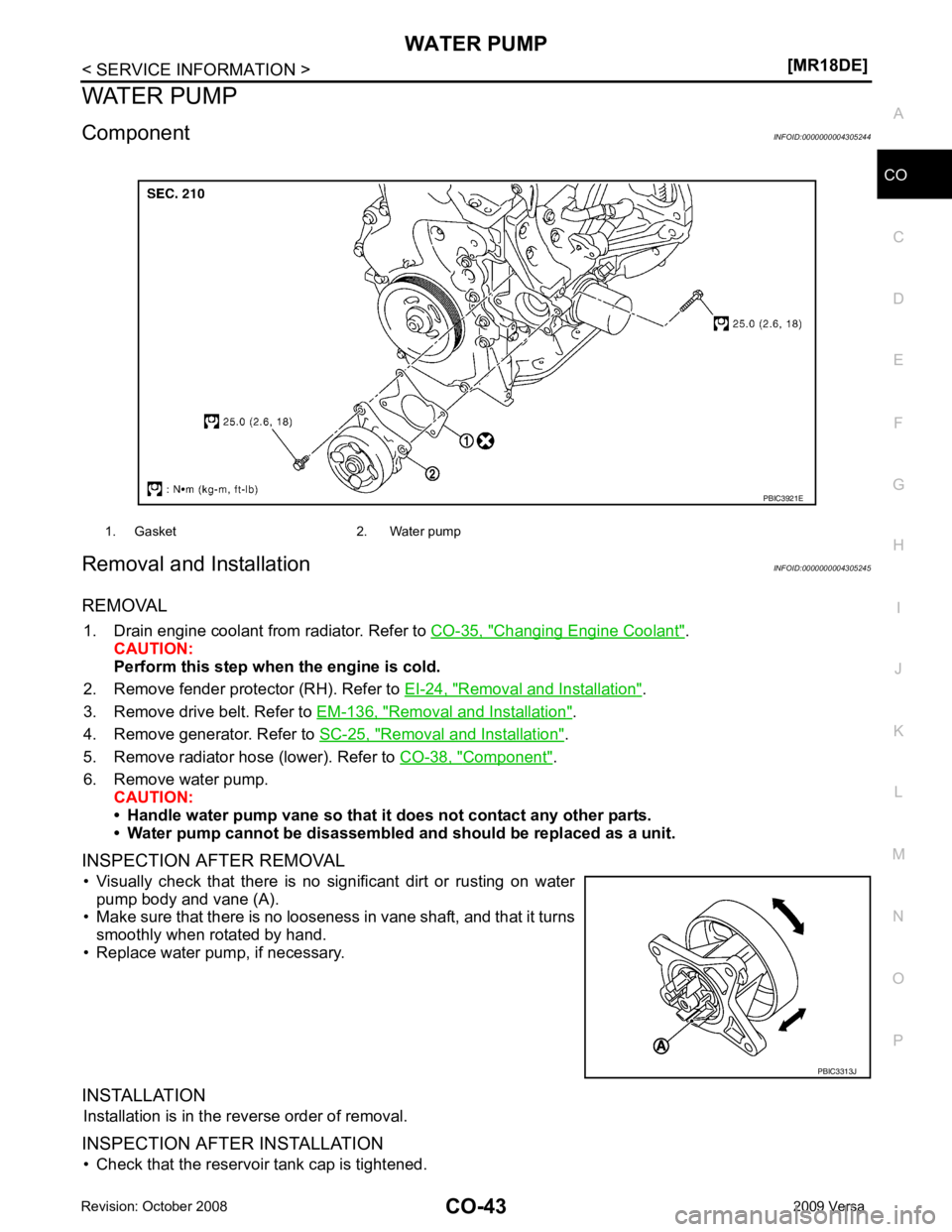
Component INFOID:0000000004305244
Removal and Installation INFOID:0000000004305245
REMOVAL 1. Drain engine coolant from radiator. Refer to CO-35, " Changing Engine Coolant " .
CAUTION:
Perform this step when the engine is cold.
2. Remove fender protector (RH). Refer to EI-24, " Removal and Installation " .
3. Remove drive belt. Refer to EM-136, " Removal and Installation " .
4. Remove generator. Refer to SC-25, " Removal and Installation " .
5. Remove radiator hose (lower). Refer to CO-38, " Component " .
6. Remove water pump. CAUTION:
• Handle water pump vane so that it does not contact any other parts.
• Water pump cannot be disassembled and should be replaced as a unit.
INSPECTION AFTER REMOVAL • Visually check that there is no significant dirt or rusting on water pump body and vane (A).
• Make sure that there is no looseness in vane shaft, and that it turns
smoothly when rotated by hand.
• Replace water pump, if necessary.
INSTALLATION Installation is in the reverse order of removal.
INSPECTION AFTER INSTALLATION • Check that the reservoir tank cap is tightened. 1. Gasket 2. Water pump
PBIC3313J
Page 939 of 4331
CO
NP
O
THERMOSTAT
Component INFOID:0000000004305246
Removal and Installation INFOID:0000000004305247
REMOVAL 1. Drain engine coolant from radiator. Refer to CO-35, " Changing Engine Coolant " .
CAUTION:
• Perform this step when engine is cold.
• Never spill engine coolant on drive belt.
2. Remove the air duct (inlet). Refer to EM-139, " Component " .
3. Remove the radiator hose (lower) from the engine. Refer to CO-38, " Component " .
4. Remove water inlet.
5. Remove thermostat.
6. Remove water pump, if necessary. Refer to CO-43 .
7. Remove thermostat housing, if necessary.
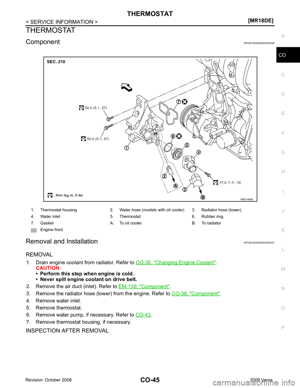
INSPECTION AFTER REMOVAL 1. Thermostat housing 2. Water hose (models with oil cooler) 3. Radiator hose (lower)
4. Water inlet 5. Thermostat 6. Rubber ring
7. Gasket A. To oil cooler B. To radiator Engine front
Page 941 of 4331
CO
NP
O
WATER OUTLET AND WATER CONTROL VALVE
Component INFOID:0000000004305248
Removal and Installation INFOID:0000000004305249
REMOVAL 1. Drain engine coolant from radiator. Refer to CO-35, " Changing Engine Coolant " .
CAUTION:
• Perform this step when engine is cold.
• Never spill engine coolant on drive belt.
2. Remove air cleaner and air duct. Refer to EM-139, " Component " .
3. Remove radiator hose (lower) from engine. Refer to CO-38, " Component " .
4. Remove heater hoses and water hoses.
5. Remove water outlet.
6. Remove water control valve.
7. Remove engine coolant temperature sensor from the water outlet, if necessary. CAUTION:
• Handle carefully to avoid any shock to engine coolant temperature sensor.
• Replace the gasket with a new one.
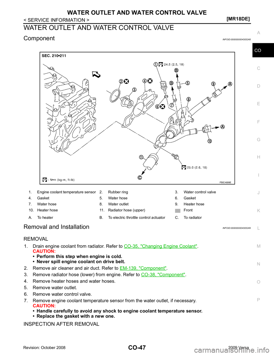
INSPECTION AFTER REMOVAL 1. Engine coolant temperature sensor 2. Rubber ring 3. Water control valve
4. Gasket 5. Water hose 6. Gasket
7. Water hose 8. Water outlet 9. Heater hose
10. Heater hose 11. Radiator hose (upper) Front
A. To heater B. To electric throttle control actuator C. To radiator
Page 945 of 4331

CVT
N
O P
CONTENTS
CVT
RE0F08A
SERVICE INFORMATION .. ..........................
9
INDEX FOR DTC ............................................ .....9
Alphabetical Index ............................................... ......9
DTC No. Index .................................................... ......9
PRECAUTIONS .............................................. ....11
Precaution for Supplemental Restraint System
(SRS) "AIR BAG" and "SEAT BELT PRE-TEN-
SIONER" ............................................................. ....
11
Precaution Necessary fo r Steering Wheel Rota-
tion After Battery Disconnect ............................... ....
11
Precaution for On Board Diagnosis (OBD) System
of CVT and Engine .............................................. ....
12
Service After Replacing TCM and Transaxle As-
sembly ................................................................. ....
12
Removal and Installation Procedure for CVT Unit
Connector ............................................................ ....
13
Precaution ........................................................... ....14
Service Notice or Precaution ............................... ....15
PREPARATION .............................................. ....16
Special Service Tool ........................................... ....16
Commercial Service Tool .................................... ....16
CVT FLUID ..................................................... ....17
Checking CVT Fluid ............................................ ....17
Changing CVT Fluid ............................................ ....18
CVT Fluid Cooler Cleanin g .....................................18
CVT SYSTEM ... .............................................. ....22
Cross-Sectional View - RE0F08A ....................... ....22
Control System .................................................... ....23
Hydraulic Control System ........................................24
TCM Function ...................................................... ....24
CAN Communication ........................................... ....25
Input/Output Signal of TCM ................................. ....26
Line Pressure and Secondary Pressure Control . ....26
Shift Control ........................................................ ....27
Lock-up and Select Control ................................. ....28 Control Valve .......................................................
....29
ON BOARD DIAGNOSTIC (OBD) SYSTEM .... 30
Introduction .......................................................... ....30
OBD-II Function for CVT System ........................ ....30
One or Two Trip Detection Logic of OBD-II ......... ....30
OBD-II Diagnostic Trouble Code (DTC) .............. ....30
Malfunction Indicator Lamp (MIL) ............................31
TROUBLE DIAGNOSIS .................................... 33
DTC Inspection Priority Chart .............................. ....33
Fail-Safe .............................................................. ....33
How to Perform Trouble Diagnosis for Quick and
Accurate Repair ................................................... ....
34
CVT Electrical Parts Location .............................. ....39
Circuit Diagram .................................................... ....40
Inspections before Trouble Diagnosis ................. ....40
Road Test ............................................................ ....44
Check before Engine Is Started ........................... ....45
Check at Idle ........................................................ ....45
Cruise Test .......................................................... ....47
Vehicle Speed When Shifting Gears ................... ....49
TCM Terminal and Refere nce Value .......................49
CONSULT-III Function (TRANSMISSION) .......... ....51
Diagnosis Procedure withou t CONSULT-III ............59
DTC U1000 CAN COMMUNICATION LINE ..... 60
Description ........................................................... ....60
On Board Diagnosis Logic ................................... ....60
Possible Cause .................................................... ....60
DTC Confirmation Procedure .............................. ....60
Wiring Diagram - CVT - CAN ............................... ....61
Diagnosis Procedure ........................................... ....62
DTC U1010 TRANSMISSION CONTROL
MODULE (CAN) ................................................ 63
Description ........................................................... ....63
On Board Diagnosis Logic ................................... ....63
Possible Cause .................................................... ....63
DTC Confirmation Procedure .............................. ....63
Diagnosis Procedure ........................................... ....63
Page 953 of 4331
CVT
N
O P
SERVICE INFORMATION
INDEX FOR DTC
Alphabetical Index INFOID:0000000004666851
NOTE:
If DTC “U1000 CAN COMM CIRCUIT” is displayed with other DTCs, first perform the trouble diagnosis
for “DTC U1000 CAN COMMUNICATION LINE”. Refer to CVT-60 .
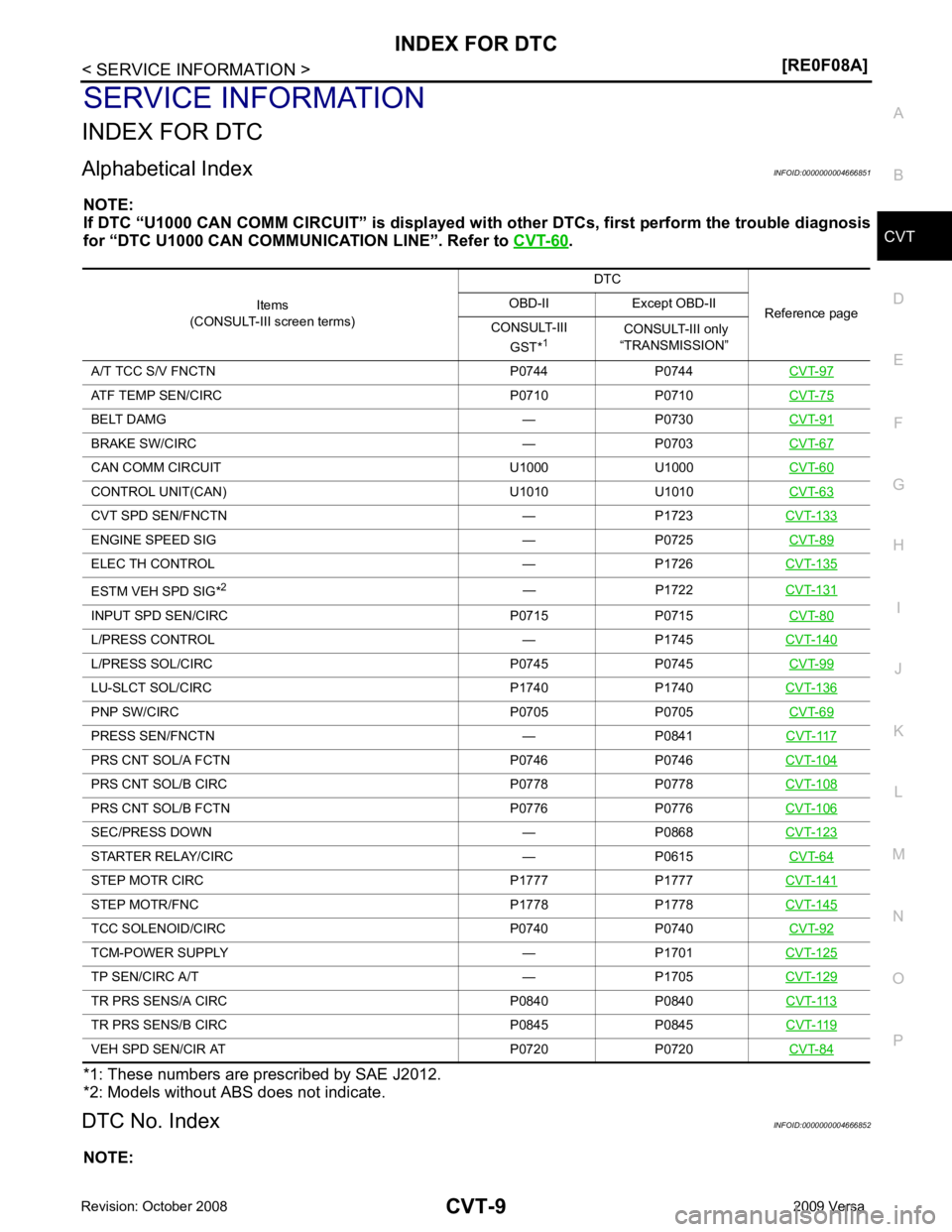
*1: These numbers are prescribed by SAE J2012.
*2: Models without ABS does not indicate.
DTC No. Index INFOID:0000000004666852
NOTE: Items
(CONSULT-III screen terms) DTC
Reference page
OBD-II Except OBD-II
CONSULT-III GST* 1 CONSULT-III only
“TRANSMISSION”
A/T TCC S/V FNCTN P0744 P0744 CVT-97ATF TEMP SEN/CIRC P0710 P0710
CVT-75BELT DAMG — P0730
CVT-91BRAKE SW/CIRC — P0703
CVT-67CAN COMM CIRCU
IT U1000 U1000 CVT-60CONTROL UNIT(CAN) U1010 U1010
CVT-63CVT SPD SEN/FNCTN — P1723
CVT-133ENGINE SPEED SIG — P0725
CVT-89ELEC TH CONTROL — P1726
CVT-135ESTM VEH SPD SIG*
2
— P1722CVT-131INPUT SPD SEN/CIRC P0715 P0715
CVT-80L/PRESS CONTROL — P1745
CVT-140L/PRESS SOL/CIRC P0745 P0745
CVT-99LU-SLCT SOL/CIRC P1740 P1740
CVT-136PNP SW/CIRC P0705 P0705
CVT-69PRESS SEN/FNCTN — P0841
CVT-117PRS CNT SOL/A FCTN P0746 P0746
CVT-104PRS CNT SOL/B CIRC P0778 P0778
CVT-108PRS CNT SOL/B FCTN P0776 P0776
CVT-106SEC/PRESS DOWN — P0868
CVT-123STARTER RELAY/CIRC — P0615
CVT-64STEP MOTR CIRC P1777 P1777
CVT-141STEP MOTR/FNC P1778 P1778
CVT-145TCC SOLENOID/CIRC P0740 P0740
CVT-92TCM-POWER SUPPLY — P1701
CVT-125TP SEN/CIRC A/T — P1705
CVT-129TR PRS SENS/A CIRC P0840 P0840
CVT-113TR PRS SENS/B CIRC P0845 P0845
CVT-119VEH SPD SEN/CIR AT P0720 P0720
CVT-84