NISSAN TIIDA 2009 Service Repair Manual
Manufacturer: NISSAN, Model Year: 2009, Model line: TIIDA, Model: NISSAN TIIDA 2009Pages: 4331, PDF Size: 58.04 MB
Page 3931 of 4331
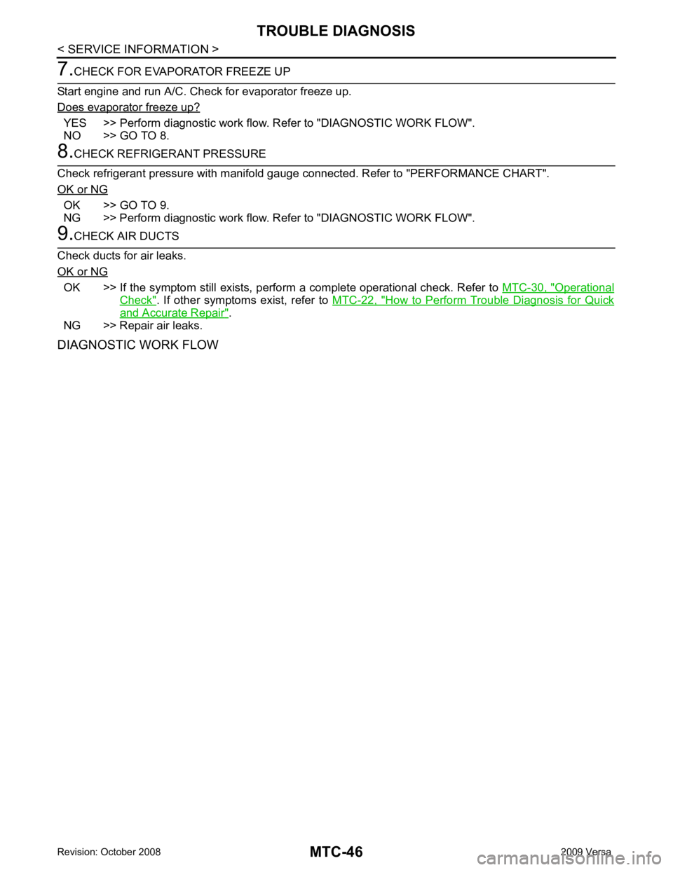
YES >> Perform diagnostic work flow. Refer to "DIAGNOSTIC WORK FLOW".
NO >> GO TO 8. OK >> GO TO 9.
NG >> Perform diagnostic work flow. Refer to "DIAGNOSTIC WORK FLOW". OK >> If the symptom still exists, perform
a complete operational check. Refer to MTC-30, " Operational
Check " . If other symptoms exist, refer to
MTC-22, " How to Perform Trouble Diagnosis for Quick
and Accurate Repair " .
NG >> Repair air leaks.
DIAGNOSTIC WORK FLOW
Page 3932 of 4331
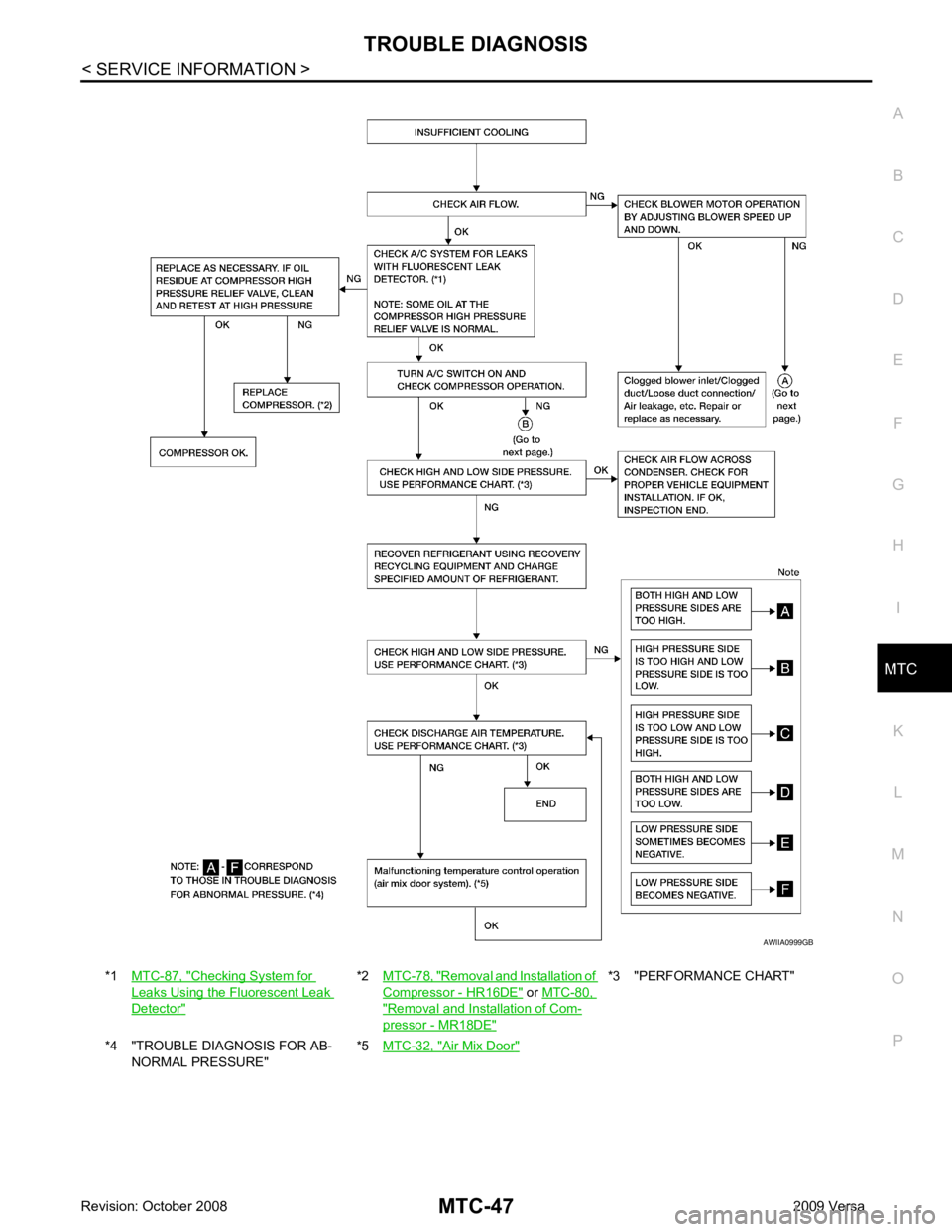
MTC
N
O P
*1
MTC-87, " Checking System for
Leaks Using the Fluorescent Leak
Detector " *2
MTC-78, " Removal and Installation of
Compressor - HR16DE " or
MTC-80, " Removal and Installation of Com-
pressor - MR18DE " *3 "PERFORMANCE CHART"
*4 "TROUBLE DIAGNOSIS FOR AB- NORMAL PRESSURE" *5
MTC-32, " Air Mix Door "
Page 3933 of 4331
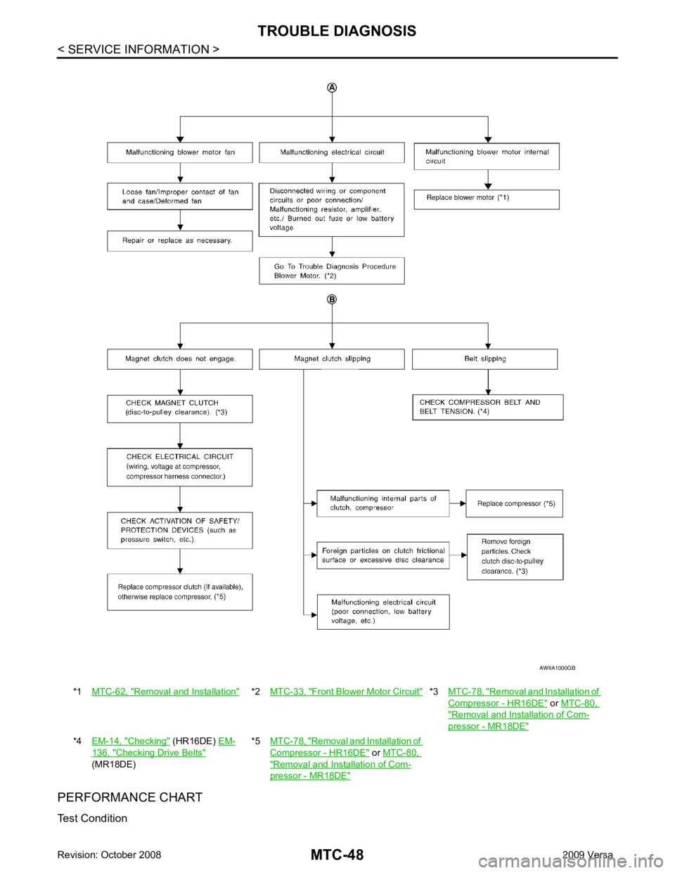
Removal and Installation " *2
MTC-33, " Front Blower Motor Circuit " *3
MTC-78, " Removal and Installation of
Compressor - HR16DE " or
MTC-80, " Removal and Installation of Com-
pressor - MR18DE "
*4
EM-14, " Checking " (HR16DE)
EM- 136, " Checking Drive Belts "
(MR18DE) *5
MTC-78, " Removal and Installation of
Compressor - HR16DE " or
MTC-80, " Removal and Installation of Com-
pressor - MR18DE "
Page 3934 of 4331

MTC
N
O P
Testing must be performed as follows:
TEST READING Recirculating-to-discharge Air Temperature Table
Ambient Air Temperature-to-operating Pressure Table
*1: With blower control dial in the "1" position
*2: With blower control dial in the "4" position.
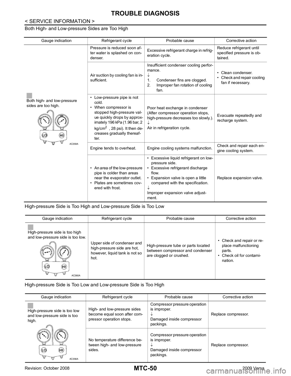
TROUBLE DIAGNOSIS FOR ABNORMAL PRESSURE Whenever system’s high and/or low side pressure(s) is /are abnormal, diagnose using a manifold gauge. The
marker above the gauge scale in the following tables indicates the standard (usual) pressure range. Since the
standard (usual) pressure, however, differs from vehicle to vehicle, refer to above table (Ambient air tempera-
ture-to-operating pressure table). Vehicle condition Indoors or in the shade (in a well-ventilated place)
Doors Closed
Door window Open
Hood Open
TEMP. Max. COLD
Mode control dial (Ventilation) set
Intake door lever (Recirculation) set
Blower speed Max. speed set
Engine speed Idle speed
Operate the air conditioning system for 10 minutes before taking measurements. Inside air (Recirculating air) at blower assembly inlet
Discharge air temperature at center ventilator
°C ( °F)
Relative humidity
% Air temperature
°C ( °F)
50 - 60 20 (68) 7.2 - 9.1 (45 - 48)
25 (77) 11.4 - 13.8 (53 - 57)
30 (86) 15.5 - 18.4 (60 - 65)
35 (95) 20.3 - 23.7 (69 - 75)
60 - 70 20 (68) 9.1 - 10.9 (48 - 52)
25 (77) 13.8 - 16.2 (57 - 61)
30 (86) 18.4 - 21.3 (65 - 70)
35 (95) 23.7 - 27.1 (75 - 81) Ambient air
High-pressure (Discharge side)
kPa (bar, kg/cm 2
, psi) Low-pressure (Suction side)
kPa (bar, kg/cm 2
, psi)
Relative humidity
% Air temperature
°C ( °F)
50 - 70 20 (68)
843 - 1,036 *1
(11.08 - 13.63, 8.6 - 10.6, 122 - 150) 159.0 - 194.0
(1.59 - 1.94, 1.62 - 1.98, 23.1 - 28.1)
25 (77) 1,094 - 1,338 *1
(10.94 - 13.38, 11.2 - 13.6, 159 - 194) 196.3 - 240.0
(1.96 - 2.40, 2.00 - 2.45, 28.5 - 34.8)
30 (86) 1,298 - 1,590 *1
(12.98 - 15.90, 13.2 - 16.2, 188 - 231) 248.0 - 302.7
(2.48 - 3.03, 2.53 - 3.09, 36.0 - 43.9)
35 (95) 1,383 - 1,688 *2
(13.83 - 16.88, 14.1 - 17.2, 201 - 245) 308.8 - 377.4
(3.09 - 3.77, 3.15 - 3.85, 44.8 - 54.7)
40 (104) 1,628 - 1,988 *2
(16.28 - 19.88, 16.6 - 20.3, 236 - 288) 377.4 - 461.2
(3.77 - 4.61, 3.85 - 4.70, 54.7 - 66.8)
Page 3935 of 4331
Page 3936 of 4331
MTC
N
O P
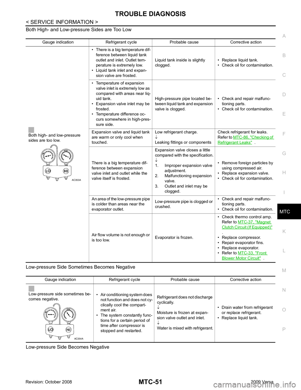
Both High- and Low-pressure Sides are Too Low
Low-pressure Side Some times Becomes Negative
Low-pressure Side Becomes Negative Gauge indication Refrigerant cycle Probable cause Corrective action
Both high- and low-pressure
sides are too low. • There is a big temperature dif-
ference between liquid tank
outlet and inlet. Outlet tem-
perature is extremely low.
• Liquid tank inlet and expan- sion valve are frosted. Liquid tank inside is slightly
clogged. • Replace liquid tank.
• Check oil for contamination.
• Temperature of expansion valve inlet is extremely low as
compared with areas near liq-
uid tank.
• Expansion valve inlet may be
frosted.
• Temperature difference oc- curs somewhere in high-pres-
sure side. High-pressure pipe located be-
tween liquid tank and expansion
valve is clogged. • Check and repair malfunc-
tioning parts.
• Check oil for contamination.
Expansion valve and liquid tank
are warm or only cool when
touched. Low refrigerant charge.
↓
Leaking fittings or components Check refrigerant for leaks.
Refer to MTC-86, " Checking of
Refrigerant Leaks " .
There is a big temperature dif-
ference between expansion
valve inlet and outlet while the
valve itself is frosted. Expansion valve closes a little
compared with the specification.
↓
1. Improper expansion valve
adjustment.
2. Malfunctioning expansion valve.
3. Outlet and inlet may be clogged. • Remove foreign particles by
using compressed air.
• Replace expansion valve.
• Check oil for contamination.
An area of the low-pressure pipe
is colder than areas near the
evaporator outlet. Low-pressure pipe is clogged or
crushed. • Check and repair malfunc-
tioning parts.
• Check oil for contamination.
Air flow volume is not enough or
is too low. Evaporator is frozen.• Check thermo control amp.
Refer to MTC-37, " Magnet
Clutch Circuit (If Equipped) "
.
• Replace compressor.
• Repair evaporator fins.
• Replace evaporator.
• Refer to MTC-33, " Front
Blower Motor Circuit " .
Page 3937 of 4331
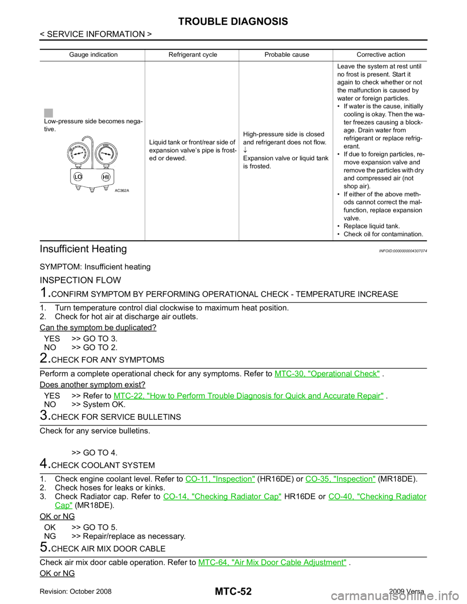
YES >> GO TO 3.
NO >> GO TO 2. Operational Check " .
Does another symptom exist? YES >> Refer to
MTC-22, " How to Perform Trouble Diagnosis for Quick and Accurate Repair " .
NO >> System OK. Inspection " (HR16DE) or
CO-35, " Inspection " (MR18DE).
2. Check hoses for leaks or kinks.
3. Check Radiator cap. Refer to CO-14, " Checking Radiator Cap " HR16DE or
CO-40, " Checking Radiator
Cap " (MR18DE).
OK or NG OK >> GO TO 5.
NG >> Repair/replace as necessary. Air Mix Door Cable Adjustment " .
OK or NG
Page 3938 of 4331
MTC
N
O P
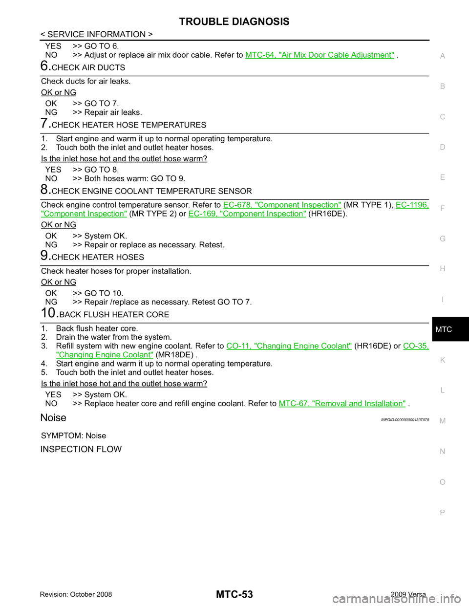
YES >> GO TO 6.
NO >> Adjust or replace air mix door cable. Refer to MTC-64, " Air Mix Door Cable Adjustment " .
OK >> GO TO 7.
NG >> Repair air leaks. YES >> GO TO 8.
NO >> Both hoses warm: GO TO 9. Component Inspection " (MR TYPE 1),
EC-1196," Component Inspection " (MR TYPE 2) or
EC-169, " Component Inspection " (HR16DE).
OK or NG OK >> System OK.
NG >> Repair or replace as necessary. Retest. OK >> GO TO 10.
NG >> Repair /replace as necessary. Retest GO TO 7. Changing Engine Coolant " (HR16DE) or
CO-35, " Changing Engine Coolant " (MR18DE) .
4. Start engine and warm it up to normal operating temperature.
5. Touch both the inlet and outlet heater hoses.
Is the inlet hose hot and the outlet hose warm? YES >> System OK.
NO >> Replace heater core and refill engine coolant. Refer to MTC-67, " Removal and Installation " .
Noise INFOID:0000000004307075
SYMPTOM: Noise
INSPECTION FLOW
Page 3939 of 4331
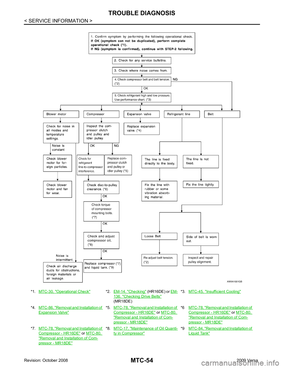
Operational Check " *2.
EM-14, " Checking " (HR16DE) or
EM- 136, " Checking Drive Belts "
(MR18DE) *3.
MTC-45, " Insufficient Cooling "
*4.
MTC-86, " Removal and Installation of
Expansion Valve " *5.
MTC-78, " Removal and Installation of
Compressor - HR16DE " or
MTC-80, " Removal and Installation of Com-
pressor - MR18DE " *6
MTC-78, " Removal and Installation of
Compressor - HR16DE " or
MTC-80, " Removal and Installation of Com-
pressor - MR18DE "
*7.
MTC-78, " Removal and Installation of
Compressor - HR16DE " or
MTC-80, " Removal and Installation of Com-
pressor - MR18DE " *8.
MTC-17, " Maintenance of Oil Quanti-
ty in Compressor " *9
MTC-84, " Removal and Installation of
Liquid Tank "
Page 3940 of 4331
MTC
N
O P
CONTROLLER
Removal and Installation INFOID:0000000004307076
REMOVAL 1. Remove cluster lid C and instrument finisher D. Refer to IP-11, " Component Parts " .
2. Remove intake door lever knob. Refer to MTC-56, " Disassembly and Assembly " .
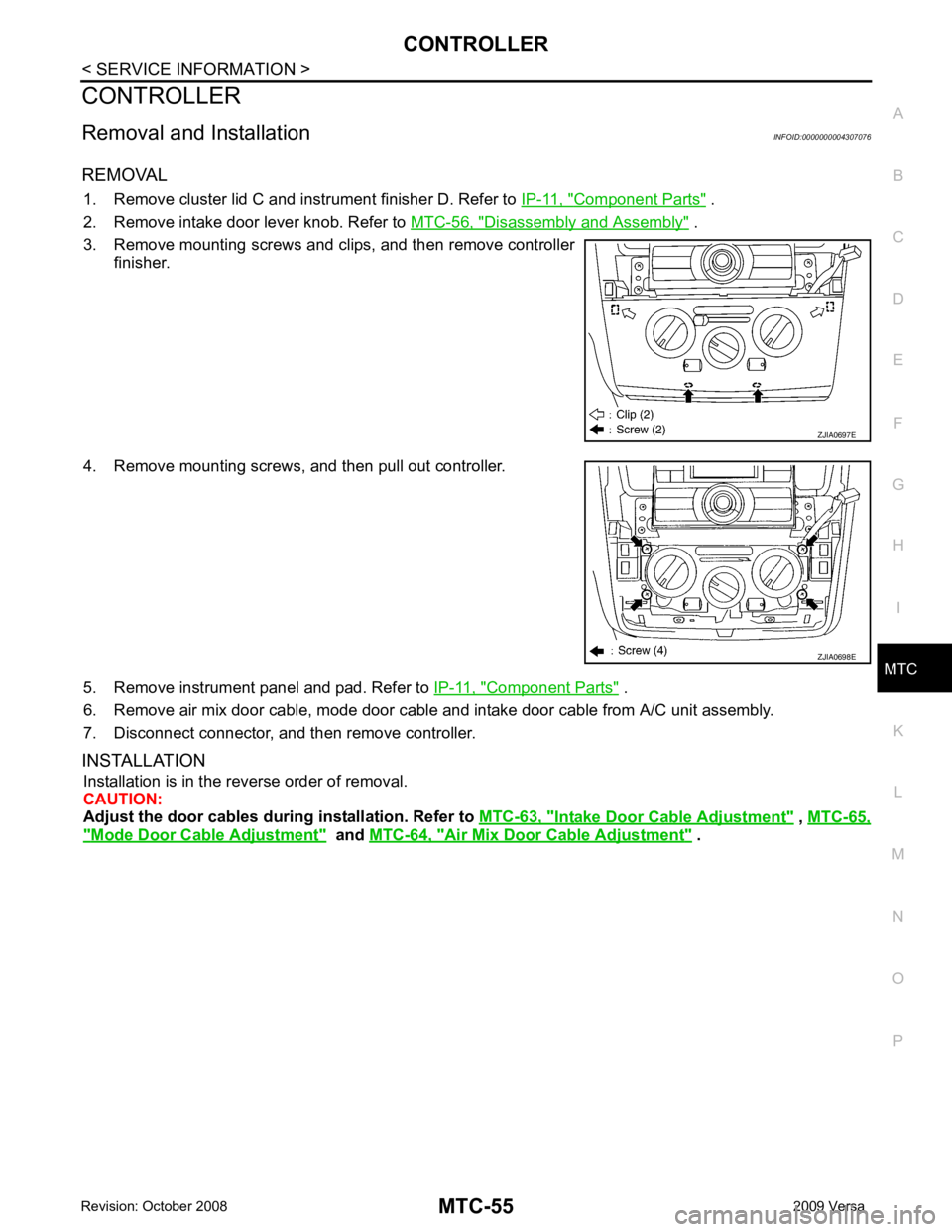
3. Remove mounting screws and clips, and then remove controller finisher.
4. Remove mounting screws, and then pull out controller.
5. Remove instrument panel and pad. Refer to IP-11, " Component Parts " .
6. Remove air mix door cable, mode door cable and intake door cable from A/C unit assembly.
7. Disconnect connector, and then remove controller.
INSTALLATION Installation is in the reverse order of removal.
CAUTION:
Adjust the door cables during installation. Refer to MTC-63, " Intake Door Cable Adjustment " ,
MTC-65, " Mode Door Cable Adjustment " and
MTC-64, " Air Mix Door Cable Adjustment " .