coolant temperature NISSAN TIIDA 2009 Service Owner's Guide
[x] Cancel search | Manufacturer: NISSAN, Model Year: 2009, Model line: TIIDA, Model: NISSAN TIIDA 2009Pages: 4331, PDF Size: 58.04 MB
Page 1445 of 4331
![NISSAN TIIDA 2009 Service Owners Guide INTAKE VALVE TIMING CONTROL
EC-89
< FUNCTION DIAGNOSIS >
[HR16DE] C
D E
F
G H
I
J
K L
M A EC
NP
O
Component Description INFOID:0000000004780038
1. Cooling fan motor harness connec-
tor 2. Crankshaft p](/img/5/57398/w960_57398-1444.png "NISSAN TIIDA 2009 Service Owners Guide INTAKE VALVE TIMING CONTROL
EC-89
< FUNCTION DIAGNOSIS >
[HR16DE] C
D E
F
G H
I
J
K L
M A EC
NP
O
Component Description INFOID:0000000004780038
1. Cooling fan motor harness connec-
tor 2. Crankshaft p")
INTAKE VALVE TIMING CONTROL
EC-89
< FUNCTION DIAGNOSIS >
[HR16DE] C
D E
F
G H
I
J
K L
M A EC
NP
O
Component Description INFOID:0000000004780038
1. Cooling fan motor harness connec-
tor 2. Crankshaft position sensor 3. Stop lamp switch
4. Brake pedal 5. Accelerator pedal position sensor harness connector6. Accelerator pedal position sensor
7. Accelerator pedal 8. Fuel level sensor unit and fuel pump harness connector (view with in-
spection hole cover removed) 9. Fuel pressure regulator
10. Fuel pump AWBIA0044ZZ
Component Reference
Camshaft position sensor (PHASE) EC-268, " Description "
Crankshaft position sensor (POS)
EC-263, " Description "
Engine coolant temperature sensor
EC-167, " Description "
Intake valve timing control solenoid valve
EC-84, " System Description "
Page 1447 of 4331
EC
NP
O
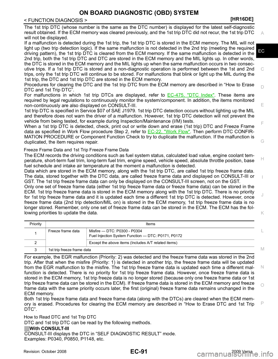
The 1st trip DTC (whose number is the same as the DT
C number) is displayed for the latest self-diagnostic
result obtained. If the ECM memory was cleared previously , and the 1st trip DTC did not recur, the 1st trip DTC
will not be displayed.
If a malfunction is detected during the 1st trip, the 1st trip DTC is stored in the ECM memory. The MIL will not
light up (two trip detection logic). If the same malfunc tion is not detected in the 2nd trip (meeting the required
driving pattern), the 1st trip DTC is cleared from the ECM memory. If the same malfunction is detected in the
2nd trip, both the 1st trip DTC and DTC are stored in t he ECM memory and the MIL lights up. In other words,
the DTC is stored in the ECM memory and the MIL light s up when the same malfunction occurs in two consec-
utive trips. If a 1st trip DTC is stored and a non-diagnostic operation is performed between the 1st and 2nd
trips, only the 1st trip DTC will continue to be stored. Fo r malfunctions that blink or light up the MIL during the
1st trip, the DTC and 1st trip DTC are stored in the ECM memory.
Procedures for clearing the DTC and the 1st trip DTC fr om the ECM memory are described in “How to Erase
DTC and 1st Trip DTC”.
For malfunctions in which 1st trip DTCs are displayed, refer to EC-475, " DTC Index " . These items are
required by legal regulations to c ontinuously monitor the system/component . In addition, the items monitored
non-continuously are also displayed on CONSULT-III.
1st trip DTC is specified in Service $07 of SAE J1979. 1st trip DTC detection occurs without lighting up the MIL
and therefore does not warn the driver of a malfunction. However, 1st trip DTC detection will not prevent the
vehicle from being tested, for example during Inspection/Maintenance (I/M) tests.
When a 1st trip DTC is detected, check, print out or write down and erase (1st trip) DTC and Freeze Frame
data as specified in Work Flow procedure Step 2, refer to EC-22, " Work Flow " . Then perform DTC CONFIR-
MATION PROCEDURE or Component Function Check to tr y to duplicate the malfunction. If the malfunction is
duplicated, the item requires repair.
Freeze Frame Data and 1st Trip Freeze Frame Data The ECM records the driving conditions such as fuel system status, calculated load value, engine coolant tem-
perature, short-term fuel trim, long-term fuel trim, engi ne speed, vehicle speed, absolute throttle position, base
fuel schedule and intake air temperature at the moment a malfunction is detected.
Data which are stored in the ECM memory, along with the 1st trip DTC, are called 1st trip freeze frame data.
The data, stored together with the DTC data, are ca lled freeze frame data and displayed on CONSULT-III or
GST. The 1st trip freeze frame data can only be di splayed on the CONSULT-III screen, not on the GST.
Only one set of freeze frame data (either 1st trip freez e frame data or freeze frame data) can be stored in the
ECM. 1st trip freeze frame data is stored in the ECM me mory along with the 1st trip DTC. There is no priority
for 1st trip freeze frame data and it is updated each time a different 1st trip DTC is detected. However, once
freeze frame data (2nd trip detection/MIL on) is stored in the ECM memory, 1st trip freeze frame data is no
longer stored. Remember, only one set of freeze frame data can be stored in the ECM. The ECM has the fol-
lowing priorities to update the data.
For example, the EGR malfunction (P riority: 2) was detected and the freeze frame data was stored in the 2nd
trip. After that when the misfire (Priority: 1) is detected in another trip, the freeze frame data will be updated
from the EGR malfunction to the misfire. The 1st trip freeze frame data is updated each time a different mal-
function is detected. There is no priority for 1st tr ip freeze frame data. However, once freeze frame data is
stored in the ECM memory, 1st trip freeze data is no longer stored (because only one freeze frame data or 1st
trip freeze frame data can be stored in the ECM). If fr eeze frame data is stored in the ECM memory and freeze
frame data with the same priority occurs later, the first (original) freeze frame data remains unchanged in the
ECM memory.
Both 1st trip freeze frame data and freeze frame dat a (along with the DTCs) are cleared when the ECM mem-
ory is erased. Procedures for clearing the ECM memory are described in “How to Erase DTC and 1st Trip
DTC”.
How to Read DTC and 1st Trip DTC DTC and 1st trip DTC can be read by the following methods.
With CONSULT-III
CONSULT-III displays the DTC in “SELF DIAGNOSTIC RESULT” mode.
Examples: P0340, P0850, P1148, etc. Priority Items
1 Freeze frame data Misfire — DTC: P0300 - P0304
Fuel Injection System Function — DTC: P0171, P0172
2 Except the above items (Includes A/T related items)
3 1st trip freeze frame data
Page 1457 of 4331

EC
NP
O
• The B counter will be cleared when the malfunction is
detected once regardless of the driving pattern.
• The B counter will be counted up when driving pattern B is satisfied without any malfunction.
• The MIL will go off when the B counter reaches 3. (*2 in “OBD SYSTEM OPERATION CHART”)
Driving pattern C means the vehicl e operation as per the following:
The following conditions should be satisfied at the same time:
Engine speed: (Engine speed in the freeze frame data) ± 375 rpm
Calculated load value: (Calculated load value in the freeze frame data) x (1 ± 0.1) [%]
Engine coolant temperature (T) condition:
• When the freeze frame data shows lower than 70 °C (158 °F), T should be lower than 70 °C (158 °F).
• When the freeze frame data shows higher than or equal to 70 °C (158 °F), T should be higher than or equal to
70 °C (158 °F).
Example:
If the stored freeze frame data is as per the following:
Engine speed: 850 rpm, Calculated load val ue: 30%, Engine coolant temperature: 80°C (176 °F)
To be satisfied with driving pattern C, the v ehicle should run under the following conditions:
Engine speed: 475 - 1,225 rpm, Calculated load value: 27 - 33%, Engine coolant temperature: more than 70°C
(158 °F)
• The C counter will be cleared when the malfunction is detected regardless of vehicle conditions above.
• The C counter will be counted up when vehicle conditions above is satisfied without the same malfunction.
• The DTC will not be displayed after C counter reaches 80.
• The 1st trip DTC will be cleared when C counter is counted once without the same malfunction after DTC is
stored in ECM.
Relationship Between MIL, DTC, 1st Tr ip DTC and Driving Patterns Except For “Misfire
Page 1462 of 4331

Monitored item Unit Description Remarks
ENG SPEED rpm • Indicates the engine speed computed from the signal
of the crankshaft position sensor (POS) and camshaft
position sensor (PHASE). • Accuracy becomes poor if engine
speed drops below the idle rpm.
• If the signal is interrupted while the engine is running, an abnormal value
may be indicated.
MAS A/F SE-B1 V • The signal voltage of the mass air flow sensor is dis-
played. • When the engine is stopped, a certain
value is indicated.
• When engine is running specification range is indicated in “SPEC”.
B/FUEL SCHDL ms • “Base fuel schedule” indicates the fuel injection pulse
width programmed into ECM, prior to any learned on
board correction. • When engine is running specification
range is indicated in “SPEC”.
A/F ALPHA-B1 % • The mean value of the air-fuel ratio feedback correc-
tion factor per cycle is indicated. • When the engine is stopped, a certain
value is indicated.
• This data also includes the data for
the air-fuel ratio learning control.
• When engine is running specification range is indicated in “SPEC”.
COOLAN TEMP/S °C or °F • The engine coolant temperature (determined by the
signal voltage of the engine coolant temperature sen-
sor) is displayed. • When the engine coolant temperature
sensor is open or short-circuited,
ECM enters fail-safe mode. The en-
gine coolant temperature determined
by the ECM is displayed.
A/F SEN1 (B1) V • The A/F signal computed from the input signal of the
air fuel ratio (A/F) se nsor 1 is displayed.
Page 1465 of 4331

EC
NP
O
Test Item
*: Leaving cooling fan OFF with CONSULT-III while engine is running may cause the engine to overheat.
DTC & SRT CONFIRMATION MODE
SRT STATUS Mode For details, refer to EC-90, " Diagnosis Description " .
SRT WORK SUPPORT Mode This mode enables a technician to drive a vehicle to set the SRT while monitoring the SRT status.
DTC WORK SUPPORT Mode TEST ITEM CONDITION JUDGMENT CHECK ITEM (REMEDY)
FUEL INJECTION • Engine: Return to the original
trouble condition
• Change the amount of fuel injec- tion using CONSULT-III. If trouble symptom disappears, see
CHECK ITEM. • Harness and connectors
• Fuel injector
• Air fuel ratio (A/F) sensor 1
IGNITION TIMING • Engine: Return to the original
trouble condition
• Timing light: Set
• Retard the ignition timing using
CONSULT-III. If trouble symptom disappears, see
CHECK ITEM. • Perform Idle Air Volume Learning.
POWER BALANCE • Engine: After warming up, idle
the engine.
• A/C switch OFF
• Selector lever: P or N position (A/ T), Neutral position (M/T)
• Cut off each fuel injector signal
one at a time using CONSULT-
III. Engine runs rough or dies.
• Harness and connectors
• Compression
• Fuel injector
• Power transistor
• Spark plug
• Ignition coil
COOLING FAN* • Ignition switch: ON
• Turn the cooling fan “LOW”, “HI”
and “OFF” using CONSULT-III. Cooling fan moves and stops.
• Harness and connectors
• IPDM E/R (Cooling fan relay)
• Cooling fan motor
ENG COOLANT
TEMP • Engine: Return to the original
trouble condition
• Change the engine coolant tem-
perature using CONSULT-III. If trouble symptom disappears, see
CHECK ITEM. • Harness and connectors
• Engine coolant temperature sen- sor
• Fuel injector
FUEL PUMP RELAY • Ignition switch: ON (Engine
stopped)
• Turn the fuel pump relay “ON”
and “OFF” using CONSULT-III
and listen to operating sound. Fuel pump relay makes the operat-
ing sound. • Harness and connectors
• Fuel pump relay
PURG VOL CONT/V • Engine: After warming up, run
engine at 1,500 rpm.
• Change the EVAP canister purge volume control solenoid
valve opening percent using
CONSULT-III. Engine speed changes according
to the opening percent. • Harness and connectors
• Solenoid valve
FUEL/T TEMP SEN • Change the fuel tank temperature using CONSULT-III.
VENT CONTROL/V • Ignition switch: ON (Engine
stopped)
• Turn solenoid valve “ON” and “OFF” using th e CONSULT-III
and listen to operating sound. Solenoid valve makes an operating
sound. • Harness and connectors
• Solenoid valve
V/T ASSIGN ANGLE • Engine: Return to the original
trouble condition
• Change intake valve timing us-
ing CONSULT-III. If trouble symptom disappears, see
CHECK ITEM. • Harness and connectors
• Intake valve timing control sole- noid valve
Page 1521 of 4331
![NISSAN TIIDA 2009 Service Owners Guide P0116 ECT SENSOR
EC-165
< COMPONENT DIAGNOSIS >
[HR16DE] C
D E
F
G H
I
J
K L
M A EC
NP
O
P0116 ECT SENSOR
Description INFOID:0000000004780447
The engine coolant temperature sensor is used to detect th](/img/5/57398/w960_57398-1520.png "NISSAN TIIDA 2009 Service Owners Guide P0116 ECT SENSOR
EC-165
< COMPONENT DIAGNOSIS >
[HR16DE] C
D E
F
G H
I
J
K L
M A EC
NP
O
P0116 ECT SENSOR
Description INFOID:0000000004780447
The engine coolant temperature sensor is used to detect th")
P0116 ECT SENSOR
EC-165
< COMPONENT DIAGNOSIS >
[HR16DE] C
D E
F
G H
I
J
K L
M A EC
NP
O
P0116 ECT SENSOR
Description INFOID:0000000004780447
The engine coolant temperature sensor is used to detect the engine
coolant temperature. The sensor modifies a voltage signal from the
ECM. The modified signal returns to the ECM as the engine coolant
temperature input. The sensor uses a thermistor which is sensitive to
the change in temperature. The electrical resistance of the ther-
mistor decreases as temperature increases.
*: These data are reference values and are measured between ECM terminal 38
(Engine coolant temperature sensor) and ground.
CAUTION:
Do not use ECM ground terminals when measuring input/output vo ltage. Doing so may result in damage to the ECM's transis-
tor. Use a ground other than ECM terminals, such as the ground.
DTC Logic INFOID:0000000004780084
DTC DETECTION LOGIC NOTE:
If DTC P0116 is displayed with P0117 or P0118, first perform the trouble diagnosis for DTC P0117,
P0118. Refer to EC-167, " DTC Logic " .
DTC CONFIRMATION PROCEDURE 1.
PRECONDITIONING
If DTC confirmation procedure has been previously conduc ted, always turn ignition switch OFF and wait at
least 10 seconds before conducting the next test.
>> GO TO 2. 2.
PERFORM DTC CONFIRMATION PROCEDURE
1. Start engine and warm it up to normal operating temperature.
2. Rev engine up to 2,000 rpm for more than 10 minutes.
3. Move the vehicle to a cool place, then stop engine and turn ignition switch OFF.
4. Check resistance between “fuel level s ensor unit and fuel pump” terminals 4 and 5. SEF594K
Engine coolant temperature
[° C ( °F)] Voltage* (V) Resistance (k
Ω)
–10 (14) 4.4 7.0 - 11.4 20 (68) 3.5 2.37 - 2.63
50 (122) 2.2 0.68 - 1.00
90 (194) 0.9 0.236 - 0.260 SEF012P
DTC No. Trouble diagnosis name DTC detecting condition Possible cause
P0116 Engine coolant temperature
sensor circuit range/perfor-
mance Engine coolant temperature signal from engine
coolant temperature sensor does not fluctuate,
even when some time has passed after starting
the engine with pre-warming up condition. • Harness or connectors
(High or low resistance in the circuit)
• Engine coolant temperature sensor
Page 1522 of 4331
YES >>
EC-166, " Diagnosis Procedure " .
NO >> INSPECTION END
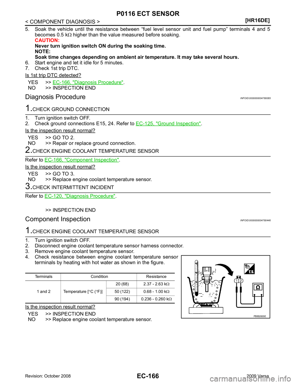
Diagnosis Procedure INFOID:0000000004780085Ground Inspection " .
Is the inspection result normal? YES >> GO TO 2.
NO >> Repair or replace ground connection. Component Inspection " .
Is the inspection result normal? YES >> GO TO 3.
NO >> Replace engine coolant temperature sensor. Diagnosis Procedure " .
>> INSPECTION END
Component Inspection INFOID:0000000004780446YES >> INSPECTION END
NO >> Replace engine coolant temperature sensor. Terminals Condition Resistance
1 and 2 Temperature [ °C ( °F)] 20 (68) 2.37 - 2.63 k
Ω
50 (122) 0.68 - 1.00 k Ω
90 (194) 0.236 - 0.260 k Ω
Page 1523 of 4331
![NISSAN TIIDA 2009 Service Owners Guide P0117, P0118 ECT SENSOR
EC-167
< COMPONENT DIAGNOSIS >
[HR16DE] C
D E
F
G H
I
J
K L
M A EC
NP
O
P0117, P0118 ECT SENSOR
Description INFOID:0000000004780087
The engine coolant temperature sensor is use](/img/5/57398/w960_57398-1522.png "NISSAN TIIDA 2009 Service Owners Guide P0117, P0118 ECT SENSOR
EC-167
< COMPONENT DIAGNOSIS >
[HR16DE] C
D E
F
G H
I
J
K L
M A EC
NP
O
P0117, P0118 ECT SENSOR
Description INFOID:0000000004780087
The engine coolant temperature sensor is use")
P0117, P0118 ECT SENSOR
EC-167
< COMPONENT DIAGNOSIS >
[HR16DE] C
D E
F
G H
I
J
K L
M A EC
NP
O
P0117, P0118 ECT SENSOR
Description INFOID:0000000004780087
The engine coolant temperature sensor is used to detect the engine
coolant temperature. The sensor modifies a voltage signal from the
ECM. The modified signal returns to the ECM as the engine coolant
temperature input. The sensor uses a thermistor which is sensitive to
the change in temperature. The electrical resistance of the ther-
mistor decreases as temperature increases.
*: These data are reference values and are measured between ECM terminal 38
(Engine coolant temperature sensor) and ground.
CAUTION:
Do not use ECM ground terminals when measuring input/output vo ltage. Doing so may result in damage to the ECM's transis-
tor. Use a ground other than ECM terminals, such as the ground.
DTC Logic INFOID:0000000004780088
DTC DETECTION LOGIC
DTC CONFIRMATION PROCEDURE 1.
PRECONDITIONING
If DTC Confirmation Procedure has been previously conduc ted, always turn ignition switch OFF and wait at
least 10 seconds before conducting the next test.
>> GO TO 2. 2.
PERFORM DTC CONFIRMATION PROCEDURE
1. Turn ignition switch ON and wait at least 5 seconds.
2. Check DTC.
Is DTC detected? YES >> Go to
EC-168, " Diagnosis Procedure " .
NO >> INSPECTION END SEF594K
Engine coolant temperature
[° C ( °F)] Voltage* (V) Resistance (k
Ω)
–10 (14) 4.4 7.0 - 11.4 20 (68) 3.5 2.37 - 2.63
50 (122) 2.2 0.68 - 1.00
90 (194) 0.9 0.236 - 0.260 SEF012P
DTC No. Trouble diagnosis name DTC detecting condition Possible Cause
P0117 Engine coolant temperature
sensor circuit low input An excessively low voltage from the sensor
is sent to ECM. • Harness or connectors
(The sensor circuit is open or shorted.)
• Engine coolant temperature sensor
P0118 Engine coolant temperature
sensor circuit high input An excessively high voltage from the sensor
is sent to ECM.
Page 1525 of 4331
EC
NP
O
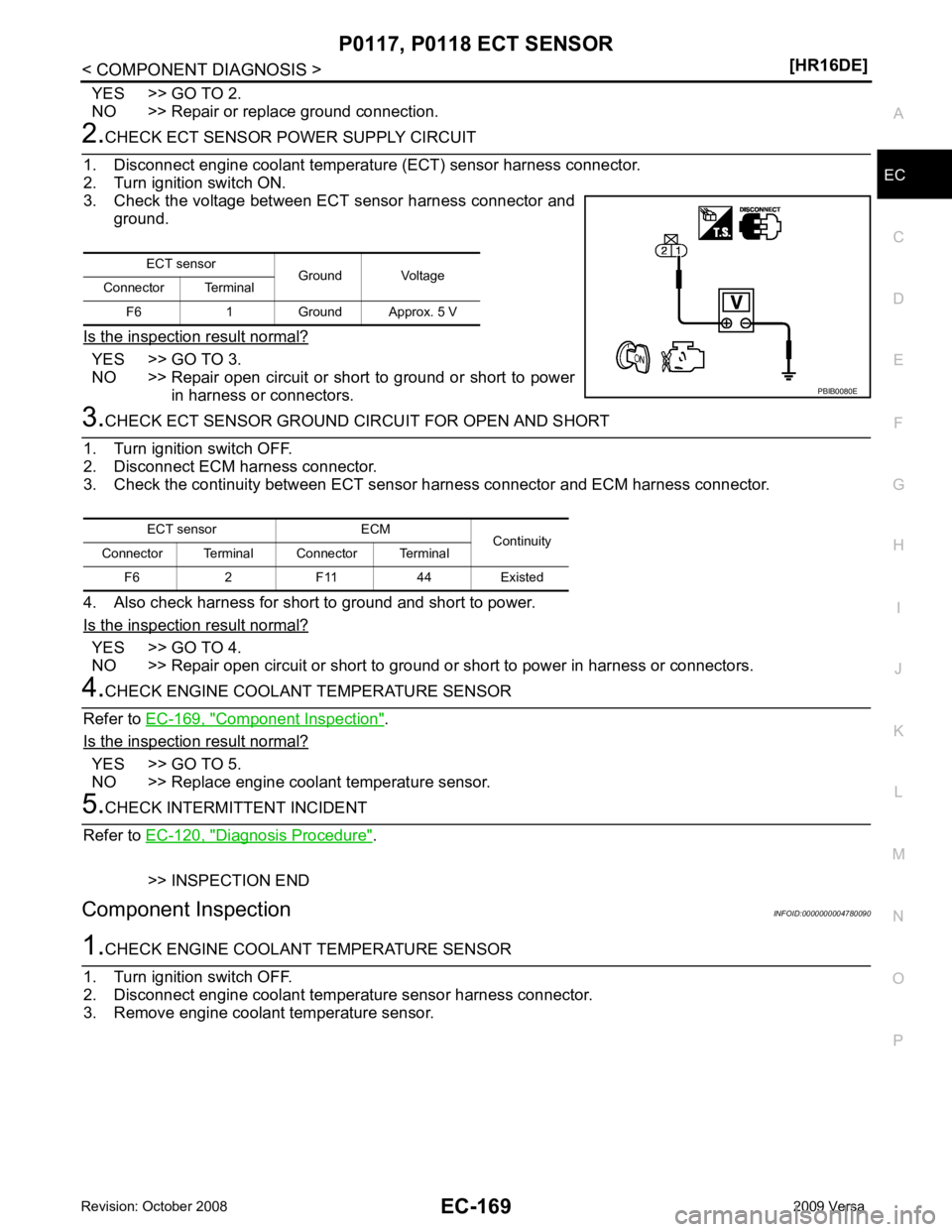
YES >> GO TO 2.
NO >> Repair or replace ground connection. YES >> GO TO 3.
NO >> Repair open circuit or short to ground or short to power
in harness or connectors. YES >> GO TO 4.
NO >> Repair open circuit or short to ground or short to power in harness or connectors. Component Inspection " .
Is the inspection result normal? YES >> GO TO 5.
NO >> Replace engine coolant temperature sensor. Diagnosis Procedure " .
>> INSPECTION END
Component Inspection INFOID:0000000004780090
Page 1526 of 4331
![NISSAN TIIDA 2009 Service Owners Guide EC-170< COMPONENT DIAGNOSIS >
[HR16DE]
P0117, P0118 ECT SENSOR
4. Check resistance between engine coolant temperature sensor terminals by heating with hot water as shown in the figure.
Is the in](/img/5/57398/w960_57398-1525.png "NISSAN TIIDA 2009 Service Owners Guide EC-170< COMPONENT DIAGNOSIS >
[HR16DE]
P0117, P0118 ECT SENSOR
4. Check resistance between engine coolant temperature sensor terminals by heating with hot water as shown in the figure.
Is the in")
EC-170< COMPONENT DIAGNOSIS >
[HR16DE]
P0117, P0118 ECT SENSOR
4. Check resistance between engine coolant temperature sensor terminals by heating with hot water as shown in the figure.
Is the inspection result normal? YES >> INSPECTION END
NO >> Replace engine coolant temperature sensor. Terminals Condition Resistance
1 and 2 Temperature [ °C ( °F)] 20 (68) 2.37 - 2.63 k
Ω
50 (122) 0.68 - 1.00 k Ω
90 (194) 0.236 - 0.260 k Ω PBIB2005E