water pump NISSAN TIIDA 2009 Service Owner's Guide
[x] Cancel search | Manufacturer: NISSAN, Model Year: 2009, Model line: TIIDA, Model: NISSAN TIIDA 2009Pages: 4331, PDF Size: 58.04 MB
Page 2962 of 4331
![NISSAN TIIDA 2009 Service Owners Guide DRIVE BELTS
EM-15
< ON-VEHICLE MAINTENANCE >
[HR16DE] C
D E
F
G H
I
J
K L
M A EM
NP
O
• When the lock nut is loosened excessively, the idle
r pulley tilts and the correct tension adju](/img/5/57398/w960_57398-2961.png "NISSAN TIIDA 2009 Service Owners Guide DRIVE BELTS
EM-15
< ON-VEHICLE MAINTENANCE >
[HR16DE] C
D E
F
G H
I
J
K L
M A EM
NP
O
• When the lock nut is loosened excessively, the idle
r pulley tilts and the correct tension adju")
DRIVE BELTS
EM-15
< ON-VEHICLE MAINTENANCE >
[HR16DE] C
D E
F
G H
I
J
K L
M A EM
NP
O
• When the lock nut is loosened excessively, the idle
r pulley tilts and the correct tension adjust-
ment cannot be performed. Never loo sen it excessively (more than 45 degrees).
• Put a matching mark on the lock nut, and check turning angle with a protractor. Never visually
check the tightening angle.
2. Adjust the belt tension by turning the adjusting bolt. CAUTION:
• When checking immediately after in stallation, first adjust it to the specified value. Then, after
turning crankshaft two turns or more, re-adjust to the specified value to avoid variation in deflec-
tion between pulleys.
• When the tension adjustment is performed, the lo ck nut should be in the condition at step“2”. If
the tension adjustment is performed when the lo ck nut is loosened more than the standard, the
idler pulley tilts and the correct tens ion adjustment cannot be performed.
3. Tighten the idler pulley lock nut.
Removal and Installation INFOID:0000000004784271
REMOVAL 1. Loosen the idler pulley lock nut (A), and then adjust the belt ten- sion by turning the adjusting bolt (B).
2. Remove drive belt.
INSTALLATION 1. Pull the idler pulley in the loosening direction, and then tempo- rarily tighten the idler pulley lock nut (A) to the following torque.
NOTE:
Do not move the lock nut from the tightened position. Proceed to step “2”.
2. Install the drive belt to each pulley. CAUTION:
• Make sure that there is no oil, grease, or coolant, etc. in pulley grooves.
• Make sure that the belt is securely inside the groove on each pulley.
3. Adjust drive belt tension by turning the adjusting bolt. Refer to EM-14, " Tension Adjustment " .
CAUTION: Idler pulley lock nut : 34.8 N·m (3.5 kg-m, 26 ft-lb)
1 : Generator
2 : Water pump
3 : Crankshaft pulley
4 : A/C compressor (with A/C models)
: Idler pulley (without A/C models)
5 : Idler pulley
6 : Drive belt PBIC3643E
1 : Generator
2 : Water pump
3 : Crankshaft pulley
4 : A/C compressor (with A/C models)
: Idler pulley (without A/C models)
5 : Idler pulley
6 : Drive belt
B : Adjusting bolt
Idler pulley lock nut : 4.4 N·m (0.45 kg-m, 39 in-lb)
(temporary tightening) PBIC3643E
Page 2997 of 4331
![NISSAN TIIDA 2009 Service Owners Guide EM-50< ON-VEHICLE REPAIR >
[HR16DE]
TIMING CHAIN
4. Remove the following parts. • Intake manifold: Refer to EM-28, " Exploded View " .
• Drive belt: Refer to EM-15, " Removal and Installation "](/img/5/57398/w960_57398-2996.png "NISSAN TIIDA 2009 Service Owners Guide EM-50< ON-VEHICLE REPAIR >
[HR16DE]
TIMING CHAIN
4. Remove the following parts. • Intake manifold: Refer to EM-28, \" Exploded View \" .
• Drive belt: Refer to EM-15, \" Removal and Installation \"")
EM-50< ON-VEHICLE REPAIR >
[HR16DE]
TIMING CHAIN
4. Remove the following parts. • Intake manifold: Refer to EM-28, " Exploded View " .
• Drive belt: Refer to EM-15, " Removal and Installation " .
• Water pump pulley: Refer to CO-20, " Exploded View " .
• Ground cable (RH)
5. Support the bottom surface of engine using a tr ansmission jack, and then remove the engine mounting
bracket and insulator (RH). Refer to EM-88, " Exploded View " .
6. Remove rocker cover. Refer to EM-46, " Exploded View " .
7. Set No. 1 cylinder at TDC of its compression stroke with the following procedure:
a. Rotate crankshaft pulley (2) clockwise and align TDC mark (without paint mark) (A) to timing indicator (1) on front cover.
b. Make sure the matching marks on each camshaft sprocket are positioned as shown.
• If not, rotate crankshaft pulley one more turn to align matching marks to the positions.
8. Remove crankshaft pulley with the following procedure:
a. Secure crankshaft pulley (1) using a suitable tool (A).
b. Loosen and pull out crankshaft pulley bolts. CAUTION:
Never remove the bolts as they are used as a supporting
point for the pulley puller.
c. Attach Tool (A) in the M 6 thread hole on crankshaft pulley, and remove crankshaft pulley. B : White paint mark (Not use for service) PBIC3673E
1 : Camshaft sprocket (EXH)
2 : Camshaft sprocket (INT)
A : Matching mark (stamp)
B : Matching mark (peripheral stamp line) PBIC3872E
PBIC3710E
B : M6 bolt
Tool number : KV11103000 ( — ) PBIC3711E
Page 3005 of 4331
Rotation " .
2. Remove front fender protector (RH). Refer to EI-24, " Removal and Installation " .
3. Drain engine oil. Refer to LU-8, " Draining " .
CAUTION:
Be sure to perform this step when engine is cold.
4. Remove the following parts. • Intake manifold: Refer to EM-28, " Exploded View " .
• Drive belt: Refer to EM-15, " Removal and Installation " .
• Water pump pulley: Refer to CO-20, " Exploded View " .
• Ground cable (RH)
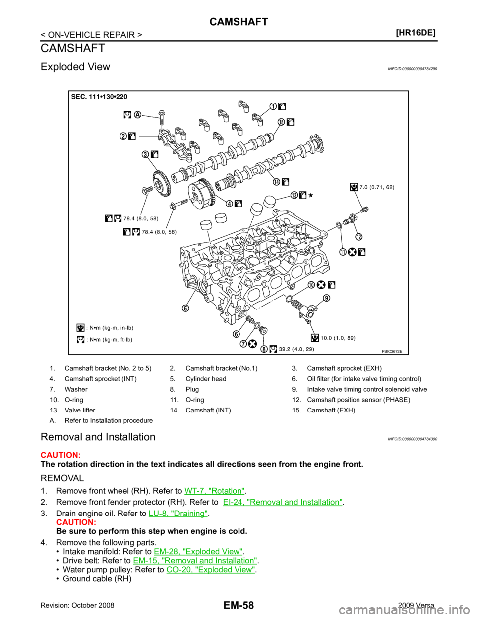
1. Camshaft bracket (No. 2 to 5) 2. Camshaft bracket (No.1) 3. Camshaft sprocket (EXH)
4. Camshaft sprocket (INT) 5. Cylinder head 6. Oil filter (for intake valve timing control)
7. Washer 8. Plug 9. Intake valve timing control solenoid valve
10. O-ring 11. O-ring 12. Camshaf t position sensor (PHASE)
13. Valve lifter 14. Camshaft (INT) 15. Camshaft (EXH)
A. Refer to Installation procedure
Page 3082 of 4331
EM
NP
O
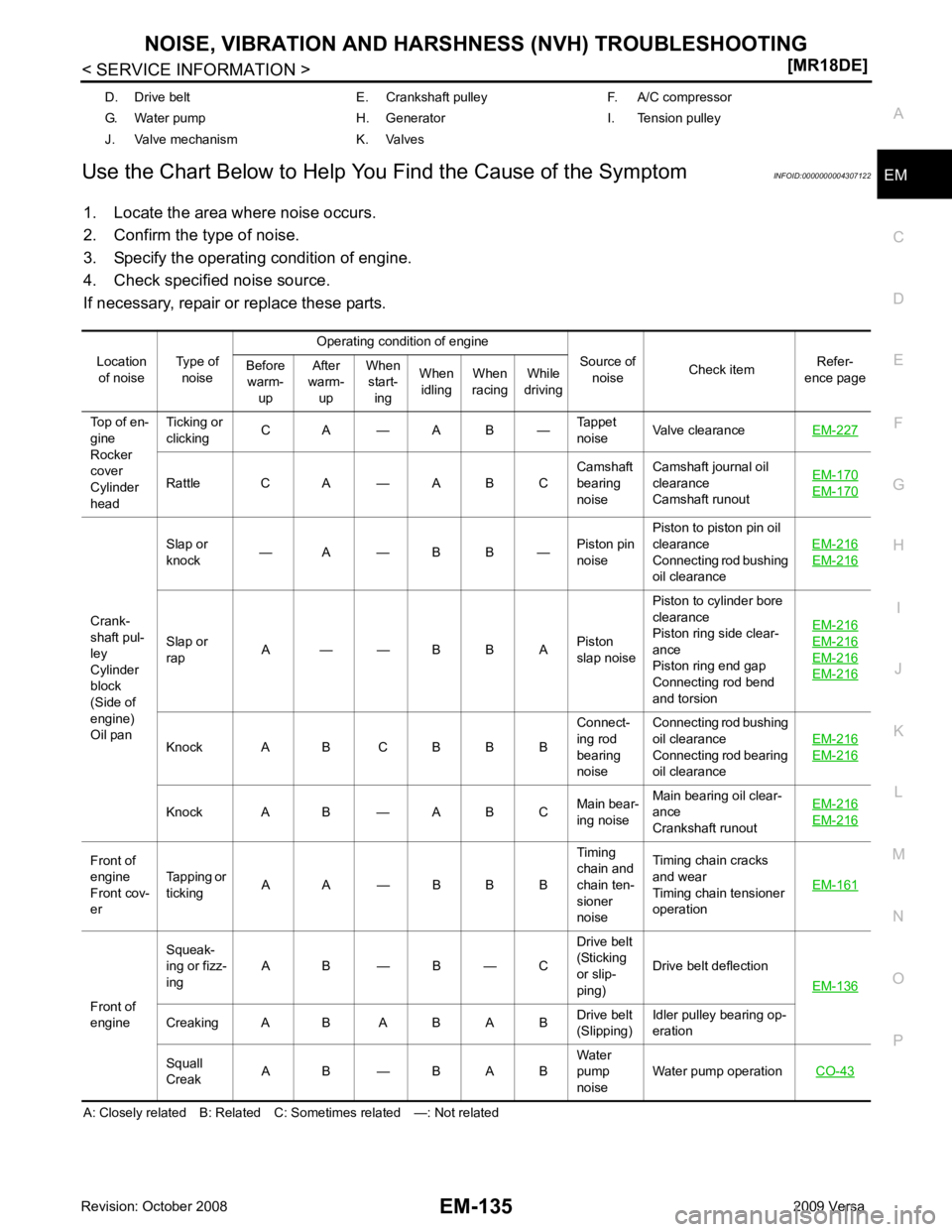
Use the Chart Below to Help You
Find the Cause of the Symptom INFOID:0000000004307122
1. Locate the area where noise occurs.
2. Confirm the type of noise.
3. Specify the operating condition of engine.
4. Check specified noise source.
If necessary, repair or replace these parts.
A: Closely related B: Related C: Sometimes related —: Not related D. Drive belt E. Crankshaft pulley F. A/C compressor
G. Water pump H. Generator I. Tension pulley
J. Valve mechanism K. Valves
Location of noise Type of
noise Operating condition of engine
Source of noise Check item
Refer-
ence page
Before
warm-
up After
warm-
up When
start-
ing When
idling When
racing While
driving
Top of en-
gine
Rocker
cover
Cylinder
head Ticking or
clicking C A — A B —
Tappet
noise Valve clearance
EM-227 Rattle C A — A B C
Camshaft
bearing
noise Camshaft journal oil
clearance
Camshaft runout EM-170 EM-170
Crank-
shaft pul-
ley
Cylinder
block
(Side of
engine)
Oil pan Slap or
knock — A — B B —
Piston pin
noise Piston to piston pin oil
clearance
Connecting rod bushing
oil clearance EM-216 EM-216
Slap or
rap A — — B B A
Piston
slap noise Piston to cylinder bore
clearance
Piston ring side clear-
ance
Piston ring end gap
Connecting rod bend
and torsion EM-216 EM-216
EM-216
EM-216
Knock A B C B B B
Connect-
ing rod
bearing
noise Connecting rod bushing
oil clearance
Connecting rod bearing
oil clearance EM-216 EM-216
Knock A B — A B C
Main bear-
ing noise Main bearing oil clear-
ance
Crankshaft runout EM-216 EM-216
Front of
engine
Front cov-
er Tapping or
ticking A A — B B B Timing
chain and
chain ten-
sioner
noise Timing chain cracks
and wear
Timing chain tensioner
operation EM-161Front of
engine Squeak-
ing or fizz-
ing A B — B — C Drive belt
(Sticking
or slip-
ping) Drive belt deflection
EM-136 Creaking A B A B A B
Drive belt
(Slipping) Idler pulley bearing op-
eration
Squall
Creak A B — B A B Water
pump
noise Water pump operation
CO-43
Page 3108 of 4331
EM
NP
O
Removal and Installation
INFOID:0000000004307143
CAUTION:
The rotating direction indicated in the text indicates all directions seen from the engine front.
REMOVAL 1. Remove front RH wheel. Refer to WT-7, " Rotation " .
2. Remove front fender protector (RH). Refer to EI-24, " Removal and Installation " .
3. Drain engine oil. Refer to LU-17, " Changing Engine Oil " .
CAUTION:
Perform this step when engine is cold.
4. Remove the following parts. • Rocker cover: Refer to EM-153, " Component " .
• Drive belt: Refer to EM-136, " Removal and Installation " .
• Water pump pulley: Refer to CO-43, " Component " .
• Ground cable (between engine bracket (RH) and radiator core support)
5. Support the bottom surface of engine using a transmission jack, and then remove the engine bracket and insulator (RH). Refer to EM-195, " Component " .
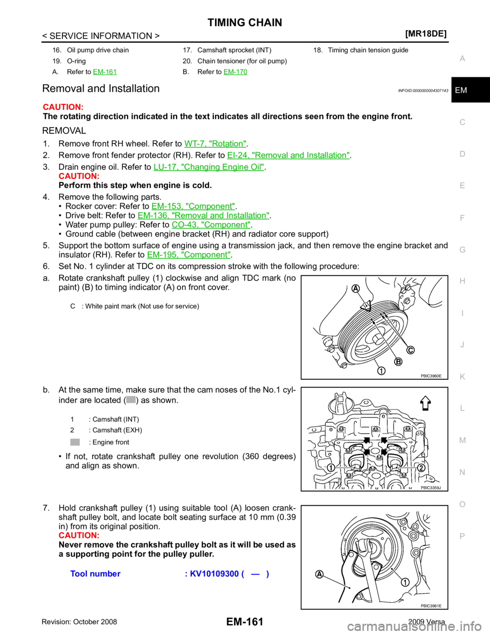
6. Set No. 1 cylinder at TDC on its compression stroke with the following procedure:
a. Rotate crankshaft pulley (1) clockwise and align TDC mark (no paint) (B) to timing indicator (A) on front cover.
b. At the same time, make sure that the cam noses of the No.1 cyl- inder are located ( ) as shown.
• If not, rotate crankshaft pulley one revolution (360 degrees) and align as shown.
7. Hold crankshaft pulley (1) using suitable tool (A) loosen crank- shaft pulley bolt, and locate bolt seating surface at 10 mm (0.39
in) from its original position.
CAUTION:
Never remove the crankshaft pulley bolt as it will be used as
a supporting point for the pulley puller.
16. Oil pump drive chain 17. Camshaft sprocket (INT) 18. Timing chain tension guide
19. O-ring 20. Chain tensioner (for oil pump)
A. Refer to EM-161 B. Refer to
EM-170 C : White paint mark (Not use for service)
Page 3759 of 4331
MA-16< SERVICE INFORMATION >
ENGINE MAINTENANCE (HR16DE)
ENGINE MAINTENANCE (HR16DE)
DRIVE BELT
DRIVE BELT : Checking INFOID:0000000004806005
• Inspection should be done only when engine is cold or over 30 minutes after the engine is stopped.
• Visually check belts for wear, damage, and cracks on inside and edges.
• Turn crankshaft pulley two time clockwise, and make sure tension on all pulleys is equal before doing the test.
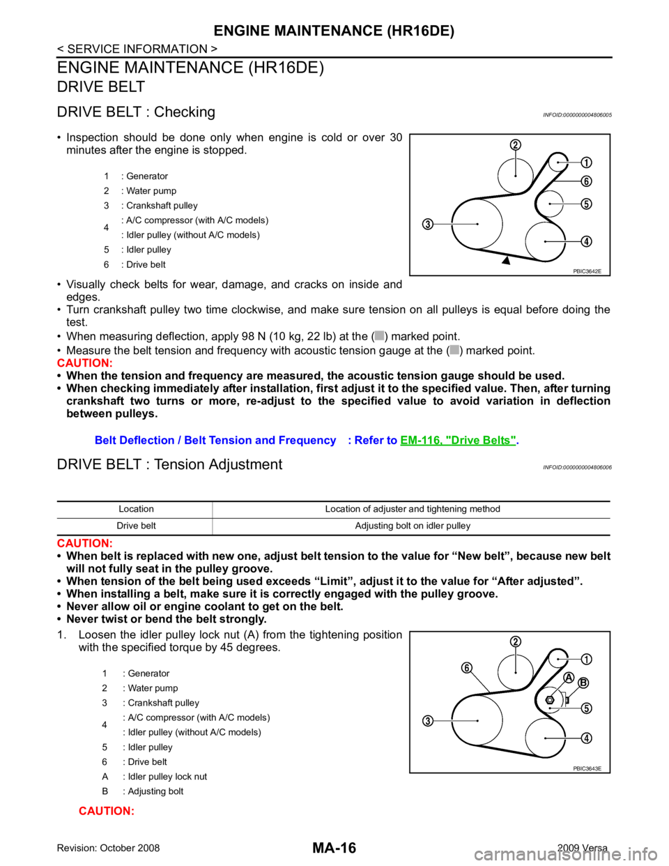
• When measuring deflection, apply 98 N (10 kg, 22 lb) at the ( ) marked point.
• Measure the belt tension and frequency with acous tic tension gauge at the ( ) marked point.
CAUTION:
• When the tension and frequency are measured, the acoustic tension gauge should be used.
• When checking immediately after installation, first ad just it to the specified value. Then, after turning
crankshaft two turns or more, re-adjust to the sp ecified value to avoid variation in deflection
between pulleys.
DRIVE BELT : Tension Adjustment INFOID:0000000004806006
CAUTION:
• When belt is replaced with new one, adjust belt tension to the value for “New belt”, because new belt
will not fully seat in the pulley groove.
• When tension of the belt being used exceeds “Limit”, adjust it to the value for “After adjusted”.
• When installing a belt, make sure it is correctly engaged with the pulley groove.
• Never allow oil or engine coolant to get on the belt.
• Never twist or bend the belt strongly.
1. Loosen the idler pulley lock nut (A) from the tightening position with the specified torque by 45 degrees.
CAUTION: 1 : Generator
2 : Water pump
3 : Crankshaft pulley
4 : A/C compressor (with A/C models)
: Idler pulley (without A/C models)
5 : Idler pulley
6 : Drive belt
Belt Deflection / Belt Tension and Frequency : Refer to EM-116, " Drive Belts " . PBIC3642E
Location Location of adjuster and tightening method
Drive belt Adjusting bolt on idler pulley
1 : Generator
2 : Water pump
3 : Crankshaft pulley
4 : A/C compressor
(with A/C models)
: Idler pulley (without A/C models)
5 : Idler pulley
6 : Drive belt
A : Idler pulley lock nut
B : Adjusting bolt PBIC3643E
Page 3769 of 4331
MA-26< SERVICE INFORMATION >
ENGINE MAINTENANCE (MR18DE)
ENGINE MAINTENANCE (MR18DE)
DRIVE BELT
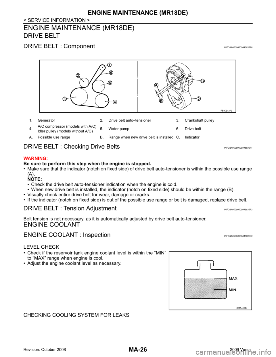
DRIVE BELT : Component INFOID:0000000004683270
DRIVE BELT : Checking Drive Belts INFOID:0000000004683271
WARNING:
Be sure to perform this step when the engine is stopped.
• Make sure that the indicator (notch on fixed side) of drive belt auto-tensioner is within the possible use range
(A).
NOTE:
• Check the drive belt auto-tensioner indication when the engine is cold.
• When new drive belt is installed, the indicator (notch on fixed side) should be within the range (B).
• Visually check entire drive belt for wear, damage or cracks.
• If the indicator (notch on fixed side) is out of t he possible use range or belt is damaged, replace drive belt.
DRIVE BELT : Tension Adjustment INFOID:0000000004683272
Belt tension is not necessary, as it is autom atically adjusted by drive belt auto-tensioner.
ENGINE COOLANT
ENGINE COOLANT : Inspection INFOID:0000000004683273
LEVEL CHECK
• Check if the reservoir tank engine coolant level is within the “MIN” to “MAX” range when engine is cool.
• Adjust the engine coolant level as necessary.
CHECKING COOLING SYSTEM FOR LEAKS 1. Generator 2. Drive belt auto–tensioner 3. Crankshaft pulley
4. A/C compressor (models with A/C)
Idler pulley (models without A/C) 5. Water pump 6. Drive belt
A. Possible use range B. Range when new drive belt is installed C. Indicator PBIC3137J
SMA412B