seats NISSAN TIIDA 2009 Service Repair Manual
[x] Cancel search | Manufacturer: NISSAN, Model Year: 2009, Model line: TIIDA, Model: NISSAN TIIDA 2009Pages: 4331, PDF Size: 58.04 MB
Page 1612 of 4331
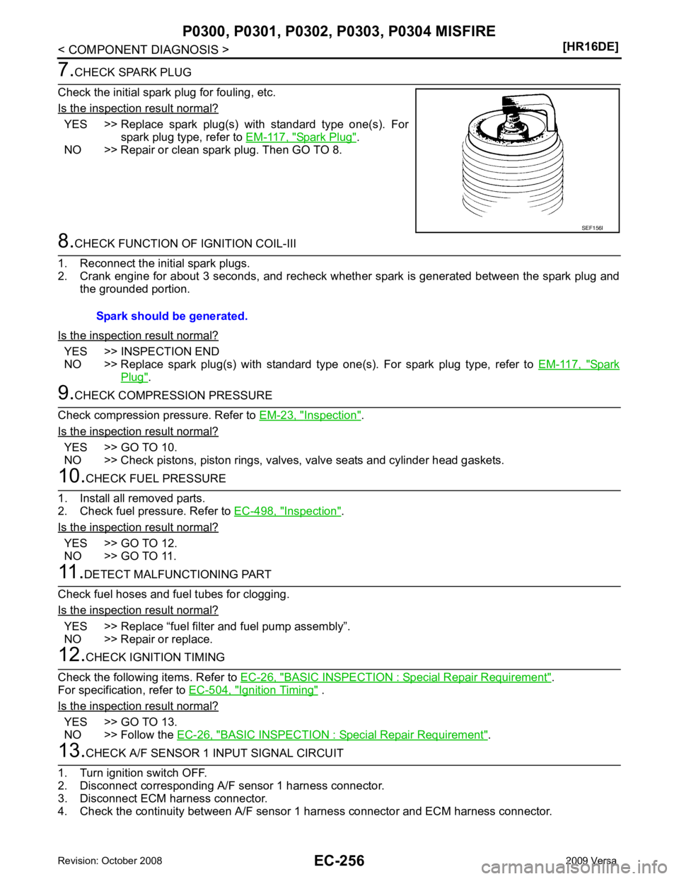
YES >> Replace spark plug(s) with standard type one(s). For
spark plug type, refer to EM-117, " Spark Plug " .
NO >> Repair or clean spark plug. Then GO TO 8. YES >> INSPECTION END
NO >> Replace spark plug(s) with standard type one(s). For spark plug type, refer to EM-117, " Spark
Plug " .
Inspection " .
Is the inspection result normal? YES >> GO TO 10.
NO >> Check pistons, piston rings, valves, valve seats and cylinder head gaskets. Inspection " .
Is the inspection result normal? YES >> GO TO 12.
NO >> GO TO 11. YES >> Replace “fuel filter and fuel pump assembly”.
NO >> Repair or replace. BASIC INSPECTION : Special Repair Requirement " .
For specification, refer to EC-504, " Ignition Timing " .
Is the inspection result normal? YES >> GO TO 13.
NO >> Follow the EC-26, " BASIC INSPECTION : Special Repair Requirement " .
Page 2124 of 4331
![NISSAN TIIDA 2009 Service Repair Manual EC-768< SERVICE INFOMATION >
[MR TYPE 1]
DTC P0300 - P0304 MULTIPLE CYLINDER
MISFIRE, NO. 1 - 4 CYLINDER MIS-
FIRE
OK or NG OK >> GO TO 7.
NG >> Check ignition coil, power transistor and their circui](/img/5/57398/w960_57398-2123.png "NISSAN TIIDA 2009 Service Repair Manual EC-768< SERVICE INFOMATION >
[MR TYPE 1]
DTC P0300 - P0304 MULTIPLE CYLINDER
MISFIRE, NO. 1 - 4 CYLINDER MIS-
FIRE
OK or NG OK >> GO TO 7.
NG >> Check ignition coil, power transistor and their circui")
EC-768< SERVICE INFOMATION >
[MR TYPE 1]
DTC P0300 - P0304 MULTIPLE CYLINDER
MISFIRE, NO. 1 - 4 CYLINDER MIS-
FIRE
OK or NG OK >> GO TO 7.
NG >> Check ignition coil, power transistor and their circuits. Refer to EC-996 .
7.
CHECK SPARK PLUG
Check the initial spark plug for fouling, etc.
OK or NG OK >> Replace spark plug(s) with standard type one(s). For
spark plug type, refer to EM-227, " Standard and Limit " .
NG >> 1. Repair or clean spark plug.
2. GO TO 8. 8.
CHECK FUNCTION OF IGNITION COIL-III
1. Reconnect the initial spark plugs.
2. Crank engine for about three seconds, and recheck whether spark is generated between the spark plug
and the grounded portion.
OK or NG OK >>
INSPECTION END
NG >> Replace spark plug(s) with standard type one(s). For spark plug type, refer to EM-227, " Standard
and Limit " .
9.
CHECK COMPRESSION PRESSURE
Check compression pressure. Refer to EM-185, " On-Vehicle Service " .
OK or NG OK >> GO TO 10.
NG >> Check pistons, piston rings, valves, valve seats and cylinder head gaskets. 10.
CHECK FUEL PRESSURE
1. Install all removed parts.
2. Release fuel pressure to zero. Refer to EC-574, " Fuel Pressure Check " .
3. Install fuel pressure gauge and check fuel pressure. Refer to EC-574, " Fuel Pressure Check " .
OK or NG OK >> GO TO 12.
NG >> GO TO 11. 11.
DETECT MALFUNCTIONING PART
Check the following.
• Fuel pump and circuit (Refer to EC-991 .)
• Fuel pressure regulator (Refer to EC-574, " Fuel Pressure Check " .)
• Fuel lines (Refer to EM-156 .)
• Fuel filter for clogging
>> Repair or replace. 12.
CHECK IGNITION TIMING
Check the following items. Refer to EC-566, " Basic Inspection " .
Spark should be generated.
SEF156I
Spark should be generated.
At idling: Approximately 350 kPa (3.57 kg/cm 2
, 51 psi)
Page 2642 of 4331
![NISSAN TIIDA 2009 Service Repair Manual EC-1286< SERVICE INFOMATION >
[MR TYPE 2]
DTC P0300 - P0304 MULTIPLE CYLINDER
MISFIRE, NO. 1 - 4 CYLINDER MIS-
FIRE
3. Crank engine for about 3 seconds, and recheck whether spark is generated between](/img/5/57398/w960_57398-2641.png "NISSAN TIIDA 2009 Service Repair Manual EC-1286< SERVICE INFOMATION >
[MR TYPE 2]
DTC P0300 - P0304 MULTIPLE CYLINDER
MISFIRE, NO. 1 - 4 CYLINDER MIS-
FIRE
3. Crank engine for about 3 seconds, and recheck whether spark is generated between")
EC-1286< SERVICE INFOMATION >
[MR TYPE 2]
DTC P0300 - P0304 MULTIPLE CYLINDER
MISFIRE, NO. 1 - 4 CYLINDER MIS-
FIRE
3. Crank engine for about 3 seconds, and recheck whether spark is generated between the spark plug and the grounded metal portion.
OK or NG OK >> GO TO 7.
NG >> Check ignition coil, power transistor and their circuits. Refer to EC-1518 .
7.
CHECK SPARK PLUG
Check the initial spark plug for fouling, etc.
OK or NG OK >> Replace spark plug(s) with standard type one(s). For
spark plug type, refer to EM-227, " Standard and Limit " .
NG >> 1. Repair or clean spark plug. 2. GO TO 8. 8.
CHECK FUNCTION OF IGNITION COIL-III
1. Reconnect the initial spark plugs.
2. Crank engine for about three seconds, and recheck whether spark is generated between the spark plug
and the grounded portion.
OK or NG OK >>
INSPECTION END
NG >> Replace spark plug(s) with standard type one(s). For spark plug type, refer to EM-227, " Standard
and Limit " .
9.
CHECK COMPRESSION PRESSURE
Check compression pressure. Refer to EM-185, " On-Vehicle Service " .
OK or NG OK >> GO TO 10.
NG >> Check pistons, piston rings, valves, valve seats and cylinder head gaskets. 10.
CHECK FUEL PRESSURE
1. Install all removed parts.
2. Release fuel pressure to zero. Refer to EC-1086, " Fuel Pressure Check " .
3. Install fuel pressure gauge and check fuel pressure. Refer to EC-1086, " Fuel Pressure Check " .
OK or NG OK >> GO TO 12.
NG >> GO TO 11. 11.
DETECT MALFUNCTIONING PART
Check the following.
• Fuel pump and circuit (Refer to EC-1513 .)
• Fuel pressure regulator (Refer to EC-1086, " Fuel Pressure Check " .)
• Fuel lines (Refer to FL-4, " Checking Fuel Line " .)
• Fuel filter for clogging
>> Repair or replace.
Spark should be generated.
SEF156I
Spark should be generated.
At idling: Approximately 350 kPa (3.57 kg/cm 2
, 51 psi)
Page 2900 of 4331

EI
N
O P
3. The trunk lid torsion bars knocking together
4. A loose license plate or bracket
Most of these incidents can be repaired by adjusting, se curing or insulating the item(s) or component(s) caus-
ing the noise.
SUNROOF/HEADLINING Noises in the sunroof/headlining area can often be traced to one of the following:
1. Sunroof lid, rail, linkage or seals making a rattle or light knocking noise
2. Sun visor shaft shaking in the holder
3. Front or rear windshield touching headliner and squeaking
Again, pressing on the components to stop the noise while duplicating the conditions can isolate most of these
incidents. Repairs usually consist of insulating with felt cloth tape.
OVERHEAD CONSOLE (FRONT AND REAR) Overhead console noises are often caused by the cons ole panel clips not being engaged correctly. Most of
these incidents are repaired by pushing up on the c onsole at the clip locations until the clips engage.
In addition look for:
1. Loose harness or harness connectors.
2. Front console map/reading lamp lens loose.
3. Loose screws at console attachment points.
SEATS When isolating seat noise it's important to note the pos ition the seat is in and the load placed on the seat when
the noise is present. These conditions should be duplic ated when verifying and isolating the cause of the
noise.
Cause of seat noise include:
1. Headrest rods and holder
2. A squeak between the seat pad cushion and frame
3. The rear seatback lock and bracket
These noises can be isolated by moving or pressing on the suspected components while duplicating the con-
ditions under which the noise occurs. Most of thes e incidents can be repaired by repositioning the component
or applying urethane tape to the contact area.
UNDERHOOD Some interior noise may be caused by components under the hood or on the engine wall. The noise is then
transmitted into the passenger compartment.
Causes of transmitted underhood noise include:
1. Any component installed on the engine wall
2. Components that pass through the engine wall
3. Engine wall mounts and connectors
4. Loose radiator pins
5. Hood bumpers out of adjustment
6. Hood striker out of adjustment
These noises can be difficult to isolate since they cannot be reached from the interior of the vehicle. The best
method is to secure, move or insulate one component at a time and test drive the vehicle. Also, engine RPM
or load can be changed to isolate the noise. Repairs c an usually be made by moving, adjusting, securing, or
insulating the component causing the noise.
Page 3033 of 4331
![NISSAN TIIDA 2009 Service Repair Manual EM-86< ON-VEHICLE REPAIR >
[HR16DE]
CYLINDER HEAD
c. Using suitable tool, press valve guide (1) from camshaft side to the dimensions as shown.
WARNING:
Cylinder head (2) contains h eat. Wear protectiv](/img/5/57398/w960_57398-3032.png "NISSAN TIIDA 2009 Service Repair Manual EM-86< ON-VEHICLE REPAIR >
[HR16DE]
CYLINDER HEAD
c. Using suitable tool, press valve guide (1) from camshaft side to the dimensions as shown.
WARNING:
Cylinder head (2) contains h eat. Wear protectiv")
EM-86< ON-VEHICLE REPAIR >
[HR16DE]
CYLINDER HEAD
c. Using suitable tool, press valve guide (1) from camshaft side to the dimensions as shown.
WARNING:
Cylinder head (2) contains h eat. Wear protective equipment
to avoid getting burned.
d. Using suitable tool (A), apply reamer finish to valve guide.
2. Install the valve seat, if necessary. CAUTION:
Replace with oversize [0.5 mm (0.020 in)] valve seat.
a. Ream cylinder head recess diameter (a) for service valve seat.
• Be sure to ream in circles concentric to valve guide center.This will enable valve to fit correctly.
b. Heat cylinder head to 110 to 130 °C (230 to 266 °F) by soaking in
heated oil (A).
c. Provide valve seats cooled well with dry ice. Force fit valve seat into cylinder head. WARNING:
• Cylinder head contains heat. Wear prot ective equipment to avoid getting burned.
• Avoid directly touching cold valve seats. Projection “H”: Refer to
EM-119, " Cylinder Head " .
PBIC3217J
Standard: Refer to
EM-119, " Cylinder Head " .
PBIC3215J
For service parts: Oversize [0.5 mm (0.020 in)]
Refer to EM-119, " Cylinder Head " .
JPBIA0188ZZ
PBIC3214J
Page 3049 of 4331
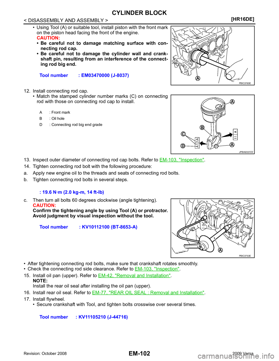
Inspection " .
14. Tighten connecting rod bolt with the following procedure:
a. Apply new engine oil to the threads and seats of connecting rod bolts.
b. Tighten connecting rod bolts in several steps.
c. Then turn all bolts 60 degrees clockwise (angle tightening). CAUTION:
Confirm the tightening angle by using Tool (A) or protractor.
Avoid judgment by visual inspection without the tool.
• After tightening connecting rod bolts, make sure that crankshaft rotates smoothly.
• Check the connecting rod side clearance. Refer to EM-103, " Inspection " .
15. Install oil pan (upper). Refer to EM-42, " Removal and Installation " .
NOTE:
Install the rear oil seal after installing the oil pan (upper).
16. Install rear oil seal. Refer to EM-77, " REAR OIL SEAL : Removal and Installation " .
17. Install flywheel. • Secure crankshaft with Tool, and tighten bolts crosswise over several times.Tool number : EM03470000 (J-8037)
Page 3140 of 4331
![NISSAN TIIDA 2009 Service Repair Manual CYLINDER HEAD
EM-193
< SERVICE INFORMATION >
[MR18DE] C
D E
F
G H
I
J
K L
M A EM
NP
O
• Check if the contact area band is continuous all around the circum-
ference.
• If not, grind to adjust valve](/img/5/57398/w960_57398-3139.png "NISSAN TIIDA 2009 Service Repair Manual CYLINDER HEAD
EM-193
< SERVICE INFORMATION >
[MR18DE] C
D E
F
G H
I
J
K L
M A EM
NP
O
• Check if the contact area band is continuous all around the circum-
ference.
• If not, grind to adjust valve")
CYLINDER HEAD
EM-193
< SERVICE INFORMATION >
[MR18DE] C
D E
F
G H
I
J
K L
M A EM
NP
O
• Check if the contact area band is continuous all around the circum-
ference.
• If not, grind to adjust valve fitti ng and check again. If the contacting
surface still has NG conditions even after the re-check, replace
valve seat.
VALVE SEAT REPLACEMENT When valve seat is removed, replace with oversized [0.5 mm (0.020 in)] valve seat.
1. Bore out old seat until it collapses. Boring shoul d not continue beyond the bottom face of the seat recess
in cylinder head. Set the machine depth stop to ensure this. Refer to EM-227, " Standard and Limit " .
2. Ream cylinder head (1) recess diameter for service valve seat.
• Be sure to ream in circles concentric to the valve guide center.This will enable valve seat to fit correctly.
3. Heat cylinder head to 110 ° to 130 °C (230 ° to 266 °F) by soaking
in heated oil (A).
4. Provide valve seats cooled well with dry ic e. Press-fit valve seat into cylinder head.
WARNING:
• Never touch cold valve seats directly.
• Cylinder head contains heat, wh en working, wear protective equipment to avoid getting burned.
5. Using valve seat cutter set or valve seat grinder, finish valve seat to the specified dimensions. For dimensions, refer to EM-227, " Standard and Limit " .
CAUTION:
When using valve seat cutter, firmly grip the cutter handle
with both hands. Then, press on the contacting surface all
around the circumference to cu t in a single drive. Improper
pressure on the cutter or cutting many different times may
result in staged valve seat.
6. Using compound, grind to adjust valve fitting.
7. Check again for normal contact. SBIA0322E
2 : Valve seat
Oversize [0.5 mm (0.020 in)] Intake : 35.200 - 35.227 mm (1.3858 - 1.3869 in)
Exhaust : 29.200 - 29.227 mm (1.1496 - 1.1507 in) PBIC3218J
PBIC3214J
SEM934C
Page 3154 of 4331
EM
NP
O
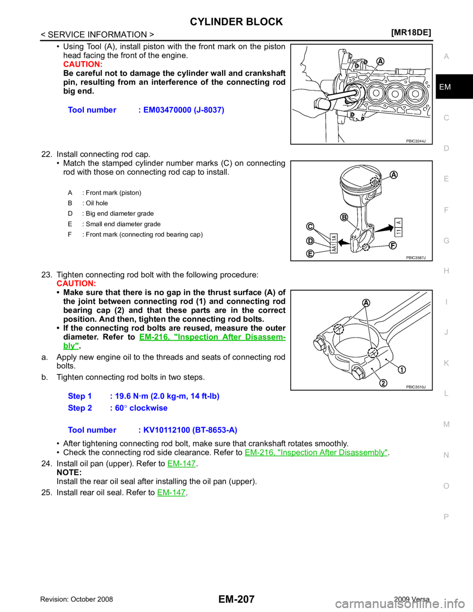
• Using Tool (A), install piston with the front mark on the piston
head facing the front of the engine.
CAUTION:
Be careful not to damage the cylinder wall and crankshaft
pin, resulting from an inte rference of the connecting rod
big end.
22. Install connecting rod cap. • Match the stamped cylinder number marks (C) on connectingrod with those on connecting rod cap to install.
23. Tighten connecting rod bolt with the following procedure: CAUTION:
• Make sure that there is no gap in the thrust surface (A) of
the joint between connecting rod (1) and connecting rod
bearing cap (2) and that these parts are in the correct
position. And then, tighten the connecting rod bolts.
• If the connecting rod bolts ar e reused, measure the outer
diameter. Refer to EM-216, " Inspection After Disassem-
bly " .
a. Apply new engine oil to the threads and seats of connecting rod bolts.
b. Tighten connecting rod bolts in two steps.
• After tightening connecting rod bolt, make sure that crankshaft rotates smoothly.
• Check the connecting rod side clearance. Refer to EM-216, " Inspection After Disassembly " .
24. Install oil pan (upper). Refer to EM-147 .
NOTE:
Install the rear oil seal after installing the oil pan (upper).
25. Install rear oil seal. Refer to EM-147 .
Tool number : EM03470000 (J-8037)
Page 3312 of 4331

GW
N
O P
Most of these incidents can be repaired by adjusting, se
curing or insulating the item(s) or component(s) caus-
ing the noise.
SUNROOF/HEADLINING Noises in the sunroof/headlining area can often be traced to one of the following:
1. Sunroof lid, rail, linkage or seals making a rattle or light knocking noise
2. Sun visor shaft shaking in the holder
3. Front or rear windshield touching headliner and squeaking
Again, pressing on the components to stop the noise while duplicating the conditions can isolate most of these
incidents. Repairs usually consist of insulating with felt cloth tape.
OVERHEAD CONSOLE (FRONT AND REAR) Overhead console noises are often caused by the cons ole panel clips not being engaged correctly. Most of
these incidents are repaired by pushing up on the c onsole at the clip locations until the clips engage.
In addition look for:
1. Loose harness or harness connectors.
2. Front console map/reading lamp lense loose.
3. Loose screws at console attachment points.
SEATS When isolating seat noise it's important to note the pos ition the seat is in and the load placed on the seat when
the noise is present. These conditions should be duplic ated when verifying and isolating the cause of the
noise.
Cause of seat noise include:
1. Headrest rods and holder
2. A squeak between the seat pad cushion and frame
3. The rear seatback lock and bracket
These noises can be isolated by moving or pressing on the suspected components while duplicating the con-
ditions under which the noise occurs. Most of thes e incidents can be repaired by repositioning the component
or applying urethane tape to the contact area.
UNDERHOOD Some interior noise may be caused by components under the hood or on the engine wall. The noise is then
transmitted into the passenger compartment.
Causes of transmitted underhood noise include:
1. Any component mounted to the engine wall
2. Components that pass through the engine wall
3. Engine wall mounts and connectors
4. Loose radiator mounting pins
5. Hood bumpers out of adjustment
6. Hood striker out of adjustment
These noises can be difficult to isolate since they cannot be reached from the interior of the vehicle. The best
method is to secure, move or insulate one component at a time and test drive the vehicle. Also, engine RPM
or load can be changed to isolate the noise. Repairs c an usually be made by moving, adjusting, securing, or
insulating the component causing the noise.
Page 3749 of 4331

Tire "
Rotation "
Rotation "
Tire Pressure Monitor-
ing System (TPMS)
t ransmitter compo-
nents Replace the TPMS transmitter grommet seal, valve core and cap when the tires
are replaced due to wear or age. WT-8 Wheel Align-
ment Inspection " and
WT-7, " Balancing
Wheels "
LOCKS, HING-
ES AND HOOD LATCH :
Lubricating Locks, Hing-
es and Hood Latch "
Item
Reference page
Warning lamps and
chimes Make sure that all warning lamps and chimes are operating properly. —
Windshield wiper and
washer Check that the wipers and washer operate properly and that the wipers do not
streak. —
Windshield defroster Check that the air comes out of the defroster outlets properly and in sufficient
quantity when operating the heater or air conditioning. —
Steering wheel Check that it has the specified play. Be sure to check for changes in the steering
condition, such as excessive play, hard steering or strange noises.
Free play: Less than 35 mm (1.38 in) —
Seats Check seat position controls such as seat adjusters, seat back recliner, etc. to
make sure they operate smoothly and that all latches lock securely in every po-
sition. Check that the head restraints move up and down smoothly and that the
locks (if equipped) hold securely in all latched positions. Check that the latches
lock securely for folding-down rear seat backs. —