height NISSAN TIIDA 2009 Service Service Manual
[x] Cancel search | Manufacturer: NISSAN, Model Year: 2009, Model line: TIIDA, Model: NISSAN TIIDA 2009Pages: 4331, PDF Size: 58.04 MB
Page 3137 of 4331
![NISSAN TIIDA 2009 Service Service Manual EM-190< SERVICE INFORMATION >
[MR18DE]
CYLINDER HEAD
3. Install valve oil seal. • Install with a valve oil seal using Tool (A) to match dimensionas shown.
NOTE:
Dimension (H) is height](/img/5/57398/w960_57398-3136.png "NISSAN TIIDA 2009 Service Service Manual EM-190< SERVICE INFORMATION >
[MR18DE]
CYLINDER HEAD
3. Install valve oil seal. • Install with a valve oil seal using Tool (A) to match dimensionas shown.
NOTE:
Dimension (H) is height")
EM-190< SERVICE INFORMATION >
[MR18DE]
CYLINDER HEAD
3. Install valve oil seal. • Install with a valve oil seal using Tool (A) to match dimensionas shown.
NOTE:
Dimension (H) is height that measured before installing valve
spring (with valve spring seat).
4. Install valve. • Install larger diameter to intake side.
5. Install valve spring (with valve spring seat). • Install smaller pitch (valve spring seat side) to cylinder head
side (B).
• Confirm identification color (A) of valve spring.
6. Install valve spring retainer.
7. Install valve collet. • Compress valve spring using Tool (A). Install valve collet with a magnet hand.
CAUTION:
When working, be careful not to damage valve lifter holes.
• Tap valve stem edge lightly with a plastic hammer after instal- lation to check its installed condition.
8. Install valve lifter. • Install it in the original position.
9. Install spark plug using suitable tool.
Inspection After Disassembly INFOID:0000000004307155
VALVE DIMENSIONS
• Check dimensions of each valve. For dimensions, refer to EM-227, " Standard and Limit " .
• If dimensions are out of the standard, replace valve.
VALVE GUIDE CLEARANCE
Valve Stem Diameter Tool number : KV10115600 (J-38958)
Height (H) : 15.1 - 15.7 mm (0.594 - 0.618 in) PBIC3211J
1 : Valve spring seat (Do not remove from valve spring.)
Intake : White
Exhaust : Orange PBIC3462J
Tool number : KV101092S0 (J-26336 B)
PBIC3209J
Page 3141 of 4331
![NISSAN TIIDA 2009 Service Service Manual EM-194< SERVICE INFORMATION >
[MR18DE]
CYLINDER HEAD
VALVE SPRING SQUARENESS
• Set try square along the side of valve spring and rotate the spring. Measure the maximum clearance between the to](/img/5/57398/w960_57398-3140.png "NISSAN TIIDA 2009 Service Service Manual EM-194< SERVICE INFORMATION >
[MR18DE]
CYLINDER HEAD
VALVE SPRING SQUARENESS
• Set try square along the side of valve spring and rotate the spring. Measure the maximum clearance between the to")
EM-194< SERVICE INFORMATION >
[MR18DE]
CYLINDER HEAD
VALVE SPRING SQUARENESS
• Set try square along the side of valve spring and rotate the spring. Measure the maximum clearance between the top of valve spring
and try square.
CAUTION:
Never remove valve spring seat from valve spring.
• If it exceeds the limit, replace valve spring (with valve spring seat).
VALVE SPRING DIMENSIONS AND VALVE SPRING PRESSURE LOAD
• Check valve spring pressure with valve spring seat installed at the specified spring height.
CAUTION:
Never remove valve spring seat from valve spring.
Standard:
• If the installation load or load with valve open is out of the standard, replace valve spring (with valve spring seat). Limit: 1.9 mm (0.075 in) PBIC0080E
SEM113
Items Intake Exhaust
Free height 44.90 - 45.10 mm (1.7677 - 1.7755 in) 45.74 - 45.94 mm (1.8007 - 1.8086 in)
Installation height 35.30 mm (1.390 in) 35.30 mm (1.390 in)
Installation load 153 - 173 N (15.6 - 17.6 kg, 34 - 39 lb) 139 - 157 N (14.2 - 16 kg, 31 - 35 lb)
Height during valve open 26.36 mm (1.0377 in) 27.80 mm (1.0944 in)
Load with valve open 335 - 377 N (34.2 - 38.5 kg, 75 - 85 lb) 266 - 297 N (27.1 - 30.3 kg, 60 - 67 lb)
Identification color White Orange
Page 3171 of 4331
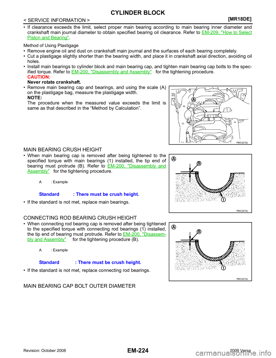
How to Select
Piston and Bearing " .
Method of Using Plastigage
• Remove engine oil and dust on crankshaft main journal and the surfaces of each bearing completely.
• Cut a plastigage slightly shorter than the bearing width, and place it in crankshaft axial direction, avoiding oil
holes.
• Install main bearings to cylinder block and main bearing cap, and tighten main bearing cap bolts to the spec- ified torque. Refer to EM-200, " Disassembly and Assembly " for the tightening procedure.
CAUTION:
Never rotate crankshaft.
• Remove main bearing cap and bearings, and using the scale (A) on the plastigage bag, measure the plastigage width.
NOTE:
The procedure when the measured value exceeds the limit is
same as that described in the “Method by Calculation”.
MAIN BEARING CRUSH HEIGHT
• When main bearing cap is removed after being tightened to the specified torque with main bearings (1) installed, the tip end of
bearing must protrude (B). Refer to EM-200, " Disassembly and
Assembly " for the tightening procedure.
• If the standard is not met, replace main bearings.
CONNECTING ROD BEARING CRUSH HEIGHT
• When connecting rod bearing cap is removed after being tightened to the specified torque with connecting rod bearings (1) installed,
the tip end of bearing must protrude. Refer to EM-200, " Disassem-
bly and Assembly " for the tightening procedure (B).
• If the standard is not met, replace connecting rod bearings.
MAIN BEARING CAP BOLT OUTER DIAMETER
Page 3174 of 4331

EM
NP
O
SERVICE DATA AND SPECIFICATIONS (SDS)
Standard and Limit INFOID:0000000004307162
GENERAL SPECIFICATIONS
DRIVE BELT
WATER CONTROL VALVE
EXHAUST MANIFOLD Unit: mm (in)
THERMOSTAT
SPARK PLUG Unit: mm (in)
CYLINDER HEAD Unit: mm (in)
Engine type
MR18DE
Cylinder arrangement In-line 4
Displacement cm3
(cu in) 1,797 (109.65)
Bore and stroke mm (in) 84.0 x 81.1 (3.307 x 3.192)
Valve arrangement DOHC
Firing order 1-3-4-2
Number of piston rings Compression 2
Oil 1
Compression ratio 9.9
Compression pressure
kPa (bar, kg/cm 2
, psi) / 250 rpm Standard 1,500 (15.0, 15.3, 217.6)
Minimum 1,200 (12.0, 12.2, 174)
Differential limit between cylinders 100 (1.0, 1.0, 15) Tension of drive belt Auto adjustment by auto-tensioner
Valve opening temperature 93.5 - 96.5
°C (200 - 206 °F)
Full-open valve lift amount 8 mm/ 108 °C (0.315 in/ 226 °F)
Valve closing temperature More than 90 °C (194 °F) Items
Limit
Surface distortion Each exhaust port 0.3 (0.012)
Entire part 0.7 (0.028) Valve opening temperature 80.5 - 83.5
°C (177 - 182 °F)
Full-open valve lift amount 8 mm/ 95 °C (0.315 in/ 203 °F)
Valve closing temperature More than 77 °C (171 °F) Make
DENSO
Standard type FXE20HR11
Spark plug gap Nominal: 1.1 (0.043)Items Standard Limit
Head surface distortion — 0.1 (0.004)
Normal cylinder head height (H) 130.9 (5.15) —
Page 3177 of 4331
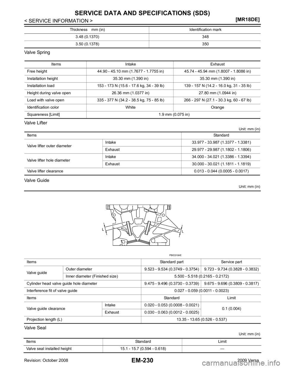
Items Intake Exhaust
Free height 44.90 - 45.10 mm (1.7677 - 1.7755 in) 45.74 - 45.94 mm (1.8007 - 1.8086 in)
Installation height 35.30 mm (1.390 in) 35.30 mm (1.390 in)
Installation load 153 - 173 N (15.6 - 17.6 kg, 34 - 39 lb) 139 - 157 N (14.2 - 16.0 kg, 31 - 35 lb)
Height during valve open 26.36 mm (1.0377 in) 27.80 mm (1.0944 in)
Load with valve open 335 - 377 N (34.2 - 38.5 kg, 75 - 85 lb) 266 - 297 N (27.1 - 30.3 kg, 60 - 67 lb)
Identification color White Orange
Squareness [Limit] 1.9 mm (0.075 in) Items
Standard
Valve lifter outer diameter Intake 33.977 - 33.987 (1.3377 - 1.3381)
Exhaust 29.977 - 29.987 (1.1802 - 1.1806)
Valve lifter hole diameter Intake 34.000 - 34.021 (1.3386 - 1.3394)
Exhaust 30.000 - 30.021 (1.1811 - 1.1819)
Valve lifter clearance 0.013 - 0.044 (0.0005 - 0.0017)Items
Standard part Service part
Valve guide Outer diameter 9.523 - 9.534 (0.3749 - 0.3754) 9.723 - 9.734 (0.3828 - 0.3832)
Inner diameter (Finished size) 5.500 - 5.518 (0.2165 - 0.2172)
Cylinder head valve guide hole diameter 9.475 - 9.496 (0.3730 - 0.3739) 9.675 - 9.696 (0.3809 - 0.3817)
Interference fit of valve guide 0.027 - 0.059 (0.0011 - 0.0023)
Items Standard Limit
Valve guide clearance Intake 0.020 - 0.053 (0.0008 - 0.0021)
0.1 (0.004)
Exhaust 0.030 - 0.063 (0.0012 - 0.0025)
Projection length (L) 13.35 - 13.65 (0.526 - 0.537)
Page 3178 of 4331
![NISSAN TIIDA 2009 Service Service Manual SERVICE DATA AND SPECIFICATIONS (SDS)
EM-231
< SERVICE INFORMATION >
[MR18DE] C
D E
F
G H
I
J
K L
M A EM
NP
O
Valve Seat
Unit: mm (in)
*: Diameter made by intersection point of conic angles ( α1) an](/img/5/57398/w960_57398-3177.png "NISSAN TIIDA 2009 Service Service Manual SERVICE DATA AND SPECIFICATIONS (SDS)
EM-231
< SERVICE INFORMATION >
[MR18DE] C
D E
F
G H
I
J
K L
M A EM
NP
O
Valve Seat
Unit: mm (in)
*: Diameter made by intersection point of conic angles ( α1) an")
SERVICE DATA AND SPECIFICATIONS (SDS)
EM-231
< SERVICE INFORMATION >
[MR18DE] C
D E
F
G H
I
J
K L
M A EM
NP
O
Valve Seat
Unit: mm (in)
*: Diameter made by intersection point of conic angles ( α1) and ( α2)
* 2
: Diameter made by intersection point of conic angles ( α2) and α3)
* 3
: Machining data
CAMSHAFT AND CAMSHAFT BEARING Unit: mm (in)
Items Standard Oversize [0.5 (0.02)] (Service)
Cylinder head seat recess diameter (D) Intake 34.700 - 34.727 (1.3661 - 1.3672) 35.200 - 35.227 (1.3858 - 1.3869)
Exhaust 28.700 - 28.727 (1.1299 - 1.1310) 29.200 - 29.227 (1.1496 - 1.1507)
Valve seat outer diameter (d) Intake 34.808 - 34.824 (1.3704 - 1.3710) 35.308 - 35.324 (1.3901 - 1.3907)
Exhaust 28.808 - 28.824 (1.1342 - 1.1348) 29.308 - 29.324 (1.1539 - 1.1545)
Valve seat interference fit 0.081 - 0.124 (0.0032 - 0.0049)
Diameter (d1)* 1 Intake 31.8 (1.252)
Exhaust 25.3 (0.996)
Diameter (d2)* 2 Intake 33.1 - 33.6 (1.303 - 1.323)
Exhaust 26.9 - 27.4 (1.059 - 1.079)
Angle ( α1) Intake 60
°
Exhaust 45 °
Angle ( α2) 88°45 ′ - 90 °15 ′
Angle ( α3) 120°
Contacting width (W)* 3Intake 1.0 - 1.4 (0.039 - 0.055)
Exhaust 1.2 - 1.6 (0.047 - 0.063)
Height (h) Intake 5.9 - 6.0 (0.232 - 0.236) 5.03 - 5.13 (0.1980 - 0.2020)
Exhaust 5.9 - 6.0 (0.232 - 0.236) 4.95 - 5.05 (0.1949 - 0.1988)
Depth (H) Intake 6.04 (0.2378)
Exhaust 6.05 (0.2382) PBIC2745E
Items Standard Limit
Camshaft journal oil clearance No. 1 0.045 - 0.086 (0.0018 - 0.0034)
0.15 (0.0059)
No. 2, 3, 4, 5 0.030 - 0.071 (0.0012 - 0.0028)
Camshaft bracket inner diameter No. 1 28.000 - 28.021 (1.1024 - 1.1032) —
No. 2, 3, 4, 5 25.000 - 25.021 (0.9843 - 0.9851) —
Camshaft journal diameter No. 1 27.935 - 27.955 (1.0998 - 1.1006) —
No. 2, 3, 4, 5 24.950 - 24.970 (0.9823 - 0.9381) —
Camshaft end play 0.075 - 0.153 (0.0030 - 0.0060) 0.24 (0.0094)
Page 3179 of 4331
![NISSAN TIIDA 2009 Service Service Manual EM-232< SERVICE INFORMATION >
[MR18DE]
SERVICE DATA AND SPECIFICATIONS (SDS)
*: Total indicator reading
CYLINDER BLOCK Unit: mm (in)
Camshaft cam height (A)
Intake 44.605 - 44.795 (1.7560 - 1.7635) 44](/img/5/57398/w960_57398-3178.png "NISSAN TIIDA 2009 Service Service Manual EM-232< SERVICE INFORMATION >
[MR18DE]
SERVICE DATA AND SPECIFICATIONS (SDS)
*: Total indicator reading
CYLINDER BLOCK Unit: mm (in)
Camshaft cam height (A)
Intake 44.605 - 44.795 (1.7560 - 1.7635) 44")
EM-232< SERVICE INFORMATION >
[MR18DE]
SERVICE DATA AND SPECIFICATIONS (SDS)
*: Total indicator reading
CYLINDER BLOCK Unit: mm (in)
Camshaft cam height (A)
Intake 44.605 - 44.795 (1.7560 - 1.7635) 44.405 (1.7482)
Exhaust 43.175 - 43.365 (1.6997 - 1.7072) 42.975 (1.6919)
Camshaft flange 3.877 - 3.925 (0.1526 - 0.1545) —
Camshaft runout [TIR*] Less than 0.02 mm (0.0008) 0.05 (0.0020)
Camshaft sprocket runout [TIR*] — 0.15 (0.0059) SEM671
Top surface distortion Limit 0.1 (0.004)
Cylinder bore Inner diameter Standard Grade No. 1 84.000 - 84.010 (3.3071 - 3.3075)
Grade No. 2 84.010 - 84.020 (3.3075 - 3.3079) PBIC4017E
Page 3180 of 4331
![NISSAN TIIDA 2009 Service Service Manual SERVICE DATA AND SPECIFICATIONS (SDS)
EM-233
< SERVICE INFORMATION >
[MR18DE] C
D E
F
G H
I
J
K L
M A EM
NP
O
PISTON, PISTON RING AND PISTON PIN
Available Piston Unit: mm (in)
Piston Ring Unit: mm (in](/img/5/57398/w960_57398-3179.png "NISSAN TIIDA 2009 Service Service Manual SERVICE DATA AND SPECIFICATIONS (SDS)
EM-233
< SERVICE INFORMATION >
[MR18DE] C
D E
F
G H
I
J
K L
M A EM
NP
O
PISTON, PISTON RING AND PISTON PIN
Available Piston Unit: mm (in)
Piston Ring Unit: mm (in")
SERVICE DATA AND SPECIFICATIONS (SDS)
EM-233
< SERVICE INFORMATION >
[MR18DE] C
D E
F
G H
I
J
K L
M A EM
NP
O
PISTON, PISTON RING AND PISTON PIN
Available Piston Unit: mm (in)
Piston Ring Unit: mm (in)
Piston Pin Out-of-round [Difference between (X) and (Y)]
Limit 0.015 (0.0006)
Taper [Difference between (A) and (C)] 0.01 (0.0004)
Main bearing housing inner diameter grade Grade No. A
Grade No. B
Grade No. C
Grade No. D
Grade No. E
Grade No. F
Grade No. G
Grade No. H
Grade No. J
Grade No. K
Grade No. L
Grade No. M
Grade No. N
Grade No. P
Grade No. R
Grade No. S
Grade No. T
Grade No. U
Grade No. V
Grade No. W 55.997 - 55.998 (2.2046 - 2.2046)
55.998 - 55.999 (2.2046 - 2.2047)
55.999 - 56.000 (2.2047 - 2.2047)
56.000 - 56.001 (2.2047 - 2.2048)
56.001 - 56.002 (2.2048 - 2.2048)
56.002 - 56.003 (2.2048 - 2.2048)
56.003 - 56.004 (2.2048 - 2.2049)
56.004 - 56.005 (2.2049 - 2.2049)
56.005 - 56.006 (2.2049 - 2.2050)
56.006 - 56.007 (2.2050 - 2.2050)
56.007 - 56.008 (2.2050 - 2.2050)
56.008 - 56.009 (2.2050 - 2.2051)
56.009 - 56.010 (2.2051 - 2.2051) 56.010 - 56.011 (2.2051 - 2.2052)
56.011 - 56.012 (2.2052 - 2.2052)
56.012 - 56.013 (2.2052 - 2.2052)
56.013 - 56.014 (2.2052 - 2.2053)
56.014 - 56.015 (2.2053 - 2.2053)
56.015 - 56.016 (2.2053 - 2.2053)
56.016 - 56.017 (2.2053 - 2.2054) Piston skirt diameter (A) Standard
Grade No. 1 83.970 - 83.980 (3.3059 - 3.3063)
Grade No. 2 83.980 - 83.990 (3.3063 - 3.3067)
Piston height (H) dimension 39.9 (1.571)
Piston pin hole diameter 19.993 - 19.999 (0.7871 - 0.7874)
Piston to cylinder bore clearance Standard 0.020 - 0.040 (0.0008 - 0.0016)
Limit 0.08 (0.0031) PBIC0188E
Items Standard Limit
Side clearance Top 0.04 - 0.08 (0.002 - 0.003) 0.11 (0.0043)
2nd 0.03 - 0.07 (0.001 - 0.003) 0.10 (0.0039)
Oil ring 0.015 - 0.185 (0.001 - 0.007) —
End gap Top 0.20 - 0.30 (0.008 - 0.012) 0.51 (0.020)
2nd 0.50 - 0.65 (0.020 - 0.026) 0.83 (0.033)
Oil (rail ring) 0.15 - 0.45 (0 .006 - 0.018) 0.78 (0.031)
Page 3194 of 4331
![NISSAN TIIDA 2009 Service Service Manual EX-10< SERVICE INFORMATION >
[MR18DE]
EXHAUST SYSTEM
• Be careful not to cut your ha nd on heat insulator edges.
CAUTION:
• Use genuine NISSAN exhaust system parts or equi valent, which a](/img/5/57398/w960_57398-3193.png "NISSAN TIIDA 2009 Service Service Manual EX-10< SERVICE INFORMATION >
[MR18DE]
EXHAUST SYSTEM
• Be careful not to cut your ha nd on heat insulator edges.
CAUTION:
• Use genuine NISSAN exhaust system parts or equi valent, which a")
EX-10< SERVICE INFORMATION >
[MR18DE]
EXHAUST SYSTEM
• Be careful not to cut your ha nd on heat insulator edges.
CAUTION:
• Use genuine NISSAN exhaust system parts or equi valent, which are specially designed for heat
resistance, corrosion resistance and shape.
REMOVAL
Remove exhaust system components using power tools.
• Remove heated oxygen sensor using Tool as needed.
CAUTION:
Be careful not to damage heated oxygen sensor.
INSTALLATION
Installation is in the reverse order of removal.
CAUTION:
• Always replace exhaust gaskets and seal bear ings with new ones when installing.
• Before installing a new heated oxygen sensor, clean and apply an ti-seize lubricant to exhaust sys-
tem threads using suitable tool.
• Discard any heated oxygen sensor which has been dropped from a height of more than 0.5 m (19.7
in) onto a hard surface such as a co ncrete floor; install a new one.
• Do not over-tighten the heated oxygen sensor. Doing so may damage the heated oxygen sensor,
resulting in the MIL coming on.
• Remove deposits from the sealing surface of each connection. Connect them securely to avoid
exhaust leakage.
• Temporarily tighten nuts on the exhaust manifold side and bolts on the vehicle side. Check each part
for unusual interference, and then ti ghten them to the specified torque.
• When installing each mounting rubb er, avoid twisting or unusual extension in up/down and right/left
directions.
Exhaust Manifold to Exhaust Front Tube
1. Securely insert seal bearing (2) into exhaust manifold (1) side in the direction shown.
• Exhaust front tube (5)
CAUTION:
Be careful not to damage seal bearing surface when install-
ing.
2. Install spring (3), tighten nut (4). • Be careful that the stud bolt nut does not interfere with the
flanged area ( ).
• Make sure the spring (3) sits properly on the flange surface by aligning it to the locator dimples.
Exhaust Front Tube to Center Muffler
1. Securely insert seal bearing (2) into exhaust front tube (1) side in the direction shown.
• Center muffler (5)
CAUTION:
Be careful not to damage seal bearing surface when install-
ing.
2. Install spring (3), tighten bolt (4). • Be careful that the stud bolt does not interfere with the flanged
area ( ).
• Make sure the spring (3) sits properly on the flange surface by
aligning it to the locator dimples.
INSPECTION AFTER INSTALLATION Tool number : KV10114400 (J-38365)
Oxygen sensor thread cleaner : — (J-43897-18)
Oxygen sensor thread cleaner : — (J-43897-12) PBIC3797E
PBIC3798E
Page 3235 of 4331

FSU
N
O P
CONTENTS
FRONT SUSPENSION
SERVICE INFORMATION .. ..........................2
PRECAUTIONS .............................................. .....2
Precaution for Supplemental Restraint System
(SRS) "AIR BAG" and "SEAT BELT PRE-TEN-
SIONER" ............................................................. ......
2
Precaution Necessary fo r Steering Wheel Rota-
tion After Battery Disconnect ............................... ......
2
Precaution for Procedure without Cowl Top Cover ......3
Cautions .............................................................. ......3
PREPARATION .............................................. .....4
Special Service Tool ........................................... ......4
Commercial Service Tool .................................... ......4
NOISE, VIBRATION AND HARSHNESS
(NVH) TROUBLESHOOTING ........................ .....6
NVH Troubleshooting Chart ................................ ......6
FRONT SUSPENSION ASSEMBLY .............. .....7 On-Vehicle Inspection and Service .....................
.....7
Wheel Alignment Inspecti on .....................................7
Component .......................................................... ....10
Removal and Installation ..................................... ....11
COIL SPRING AND STRUT .............................. 12
Removal and Installation ..................................... ....12
Disassembly and Assembly ................................. ....12
TRANSVERSE LI NK ......................................... 15
Removal and Installation ..................................... ....15
STABILIZER BAR ............................................. 16
Removal and Installation ..................................... ....16
SERVICE DATA AND SPECIFICATIONS
(SDS) ................................................................. 17
Wheel Alignment (Unladen*) ............................... ....17
Ball Joint .............................................................. ....18
Wheelarch Height (Unladen*) .............................. ....19