height NISSAN TIIDA 2009 Service Owner's Manual
[x] Cancel search | Manufacturer: NISSAN, Model Year: 2009, Model line: TIIDA, Model: NISSAN TIIDA 2009Pages: 4331, PDF Size: 58.04 MB
Page 2570 of 4331
![NISSAN TIIDA 2009 Service Owners Manual EC-1214< SERVICE INFOMATION >
[MR TYPE 2]
DTC P0130 A/F SENSOR 1
3. Check voltage between A/F sensor 1 terminal 4 and ground with CONSULT-III or tester.
OK or NG OK >> GO TO 4.
NG >> GO TO 3. 3.
DETEC](/img/5/57398/w960_57398-2569.png "NISSAN TIIDA 2009 Service Owners Manual EC-1214< SERVICE INFOMATION >
[MR TYPE 2]
DTC P0130 A/F SENSOR 1
3. Check voltage between A/F sensor 1 terminal 4 and ground with CONSULT-III or tester.
OK or NG OK >> GO TO 4.
NG >> GO TO 3. 3.
DETEC")
EC-1214< SERVICE INFOMATION >
[MR TYPE 2]
DTC P0130 A/F SENSOR 1
3. Check voltage between A/F sensor 1 terminal 4 and ground with CONSULT-III or tester.
OK or NG OK >> GO TO 4.
NG >> GO TO 3. 3.
DETECT MALFUNCTIONING PART
Check the following.
• Harness connectors E8, F8
• Harness for open or short between A/F sensor 1 and fuse
>> Repair or replace harness or connectors. 4.
CHECK A/F SENSOR 1 INPUT SIGN AL CIRCUIT FOR OPEN AND SHORT
1. Turn ignition switch OFF.
2. Disconnect ECM harness connector.
3. Check harness continuity between the following terminals. Refer to Wiring Diagram.
4. Check harness continuity between ECM terminals 49, 53 or A/F sensor 1 terminals 1, 2 and ground. Refer to Wiring Diagram.
5. Also check harness for short to power.
OK or NG OK >> GO TO 5.
NG >> Repair open circuit or short to ground or short to power in harness or connectors. 5.
CHECK INTERMITTENT INCIDENT
Perform EC-1138 .
OK or NG OK >> GO TO 6.
NG >> Repair or replace. 6.
REPLACE AIR FUEL RATIO (A/F) SENSOR 1
Replace air fuel ratio (A/F) sensor 1.
CAUTION:
• Discard any A/F sensor which has b een dropped from a height of more than 0.5 m (19.7 in) onto a
hard surface such as a concrete floor; use a new one.
• Before installing new A/F sensor, clean exhau st system threads using Oxygen Sensor Thread
Cleaner tool J-43897-18 or J-43897-12 and approved anti-seize lubricant.
>> INSPECTION END
Voltage: Battery voltage
PBIB3308E
A/F sensor 1 terminal ECM terminal
1 49
2 53
Continuity should exist.
Continuity should not exist.
Page 2576 of 4331
![NISSAN TIIDA 2009 Service Owners Manual EC-1220< SERVICE INFOMATION >
[MR TYPE 2]
DTC P0131 A/F SENSOR 1
3. Check voltage between A/F sensor 1 terminal 4 and ground with CONSULT-III or tester.
OK or NG OK >> GO TO 4.
NG >> GO TO 3. 3.
DETEC](/img/5/57398/w960_57398-2575.png "NISSAN TIIDA 2009 Service Owners Manual EC-1220< SERVICE INFOMATION >
[MR TYPE 2]
DTC P0131 A/F SENSOR 1
3. Check voltage between A/F sensor 1 terminal 4 and ground with CONSULT-III or tester.
OK or NG OK >> GO TO 4.
NG >> GO TO 3. 3.
DETEC")
EC-1220< SERVICE INFOMATION >
[MR TYPE 2]
DTC P0131 A/F SENSOR 1
3. Check voltage between A/F sensor 1 terminal 4 and ground with CONSULT-III or tester.
OK or NG OK >> GO TO 4.
NG >> GO TO 3. 3.
DETECT MALFUNCTIONING PART
Check the following.
• Harness connectors E8, F8
• Harness for open or short between A/F sensor 1 and fuse
>> Repair or replace harness or connectors. 4.
CHECK A/F SENSOR 1 INPUT SIGN AL CIRCUIT FOR OPEN AND SHORT
1. Turn ignition switch OFF.
2. Disconnect ECM harness connector.
3. Check harness continuity between the following terminals. Refer to Wiring Diagram.
4. Check harness continuity between ECM terminals 49, 53 or A/F sensor 1 terminals 1, 2 and ground. Refer to Wiring Diagram.
5. Also check harness for short to power.
OK or NG OK >> GO TO 5.
NG >> Repair open circuit or short to ground or short to power in harness or connectors. 5.
CHECK INTERMITTENT INCIDENT
Perform EC-1138 .
OK or NG OK >> GO TO 6.
NG >> Repair or replace. 6.
REPLACE AIR FUEL RATIO (A/F) SENSOR 1
Replace air fuel ratio (A/F) sensor 1.
CAUTION:
• Discard any A/F sensor which has b een dropped from a height of more than 0.5 m (19.7 in) onto a
hard surface such as a concrete floor; use a new one.
• Before installing new A/F sensor, clean exhau st system threads using Oxygen Sensor Thread
Cleaner tool J-43897-18 or J-43897-12 and approved anti-seize lubricant.
>> INSPECTION END
Voltage: Battery voltage
PBIB3308E
A/F sensor 1 terminal ECM terminal
1 49
2 53
Continuity should exist.
Continuity should not exist.
Page 2582 of 4331
![NISSAN TIIDA 2009 Service Owners Manual EC-1226< SERVICE INFOMATION >
[MR TYPE 2]
DTC P0132 A/F SENSOR 1
3. Check voltage between A/F sensor 1 terminal 4 and ground with CONSULT-III or tester.
OK or NG OK >> GO TO 4.
NG >> GO TO 3. 3.
DETEC](/img/5/57398/w960_57398-2581.png "NISSAN TIIDA 2009 Service Owners Manual EC-1226< SERVICE INFOMATION >
[MR TYPE 2]
DTC P0132 A/F SENSOR 1
3. Check voltage between A/F sensor 1 terminal 4 and ground with CONSULT-III or tester.
OK or NG OK >> GO TO 4.
NG >> GO TO 3. 3.
DETEC")
EC-1226< SERVICE INFOMATION >
[MR TYPE 2]
DTC P0132 A/F SENSOR 1
3. Check voltage between A/F sensor 1 terminal 4 and ground with CONSULT-III or tester.
OK or NG OK >> GO TO 4.
NG >> GO TO 3. 3.
DETECT MALFUNCTIONING PART
Check the following.
• Harness connectors E8, F8
• Harness for open or short between A/F sensor 1 and fuse
>> Repair or replace harness or connectors. 4.
CHECK A/F SENSOR 1 INPUT SIGN AL CIRCUIT FOR OPEN AND SHORT
1. Turn ignition switch OFF.
2. Disconnect ECM harness connector.
3. Check harness continuity between the following terminals. Refer to Wiring Diagram.
4. Check harness continuity between ECM terminals 49, 53 or A/F sensor 1 terminals 1, 2 and ground. Refer to Wiring Diagram.
5. Also check harness for short to power.
OK or NG OK >> GO TO 5.
NG >> Repair open circuit or short to ground or short to power in harness or connectors. 5.
CHECK INTERMITTENT INCIDENT
Perform EC-1138 .
OK or NG OK >> GO TO 6.
NG >> Repair or replace. 6.
REPLACE AIR FUEL RATIO (A/F) SENSOR 1
Replace air fuel ratio (A/F) sensor 1.
CAUTION:
• Discard any A/F sensor which has b een dropped from a height of more than 0.5 m (19.7 in) onto a
hard surface such as a concrete floor; use a new one.
• Before installing new A/F sensor, clean exhau st system threads using Oxygen Sensor Thread
Cleaner tool J-43897-18 or J-43897-12 and approved anti-seize lubricant.
>> INSPECTION END
Voltage: Battery voltage
PBIB3308E
A/F sensor 1 terminal ECM terminal
1 49
2 53
Continuity should exist.
Continuity should not exist.
Page 2596 of 4331
![NISSAN TIIDA 2009 Service Owners Manual EC-1240< SERVICE INFOMATION >
[MR TYPE 2]
DTC P0137 HO2S2
OK >> GO TO 6.
NG >> Replace heated oxygen sensor 2. 6.
CHECK INTERMITTENT INCIDENT
Refer to EC-1138 .
>> INSPECTION END
Component Inspection](/img/5/57398/w960_57398-2595.png "NISSAN TIIDA 2009 Service Owners Manual EC-1240< SERVICE INFOMATION >
[MR TYPE 2]
DTC P0137 HO2S2
OK >> GO TO 6.
NG >> Replace heated oxygen sensor 2. 6.
CHECK INTERMITTENT INCIDENT
Refer to EC-1138 .
>> INSPECTION END
Component Inspection")
EC-1240< SERVICE INFOMATION >
[MR TYPE 2]
DTC P0137 HO2S2
OK >> GO TO 6.
NG >> Replace heated oxygen sensor 2. 6.
CHECK INTERMITTENT INCIDENT
Refer to EC-1138 .
>> INSPECTION END
Component Inspection INFOID:0000000004500090
HEATED OXYGEN SENSOR 2 With CONSULT-III
1. Start engine and warm it up to the normal operating temperature.
2. Turn ignition switch OFF and wait at least 10 seconds.
3. Start engine and keep the engine speed between 3,500 and 4,000 rpm for at least 1 minute under no load.
4. Let engine idle for 1 minute.
5. Select “FUEL INJECTION” in “ACT IVE TEST” mode, and select “HO2S2 (B1)” as the monitor item with
CONSULT-III.
6. Check “HO2S2 (B1)” at idle speed when adjusting “FUEL INJECTION” to ±25%.
“HO2S2 (B1)” should be above 0.68V at least once when the “FUEL INJECTION” is +25%.
“HO2S2 (B1)” should be below 0.18V at least once when the “FUEL INJECTION” is −25%.
CAUTION:
• Discard any heated oxygen senso r which has been dropped from a height of more than 0.5 m
(19.7 in) onto a hard surface such as a concrete floor; use a new one.
• Before installing new oxygen sensor, clean exhaust system threads using Oxygen Sensor
Thread Cleaner tool J-43897-18 or J-43897-12 and approved anti-seize lubricant.
Without CONSULT-III
1. Start engine and warm it up to the normal operating temperature.
2. Turn ignition switch OFF and wait at least 10 seconds.
3. Start engine and keep the engine speed between 3,500 and 4,000 rpm for at least 1 minute under no load.
4. Let engine idle for 1 minute.
5. Set voltmeter probes between ECM terminal 50 (HO2S2 signal) and ground.
6. Check the voltage when revving up to 4,000 rpm under no load at least 10 times.
(Depress and release accelerator pedal as soon as possible.)
The voltage should be above 0.68V and below 0.18V at least
once during this procedure.
If the voltage can be confirmed at step 6, step 7 is not nec-
essary.
7. Keep vehicle idling for 10 minutes, then check voltage. Or check the voltage when coasting from 80 km/h (50 MPH) in D position
with OD OFF (A/T), D position (CVT) or 3rd gear position (M/T).
The voltage should be above 0.68 and below 0.18V at least
once during this procedure.
8. If NG, replace heated oxygen sensor 2. PBIB3458E
PBIB2996E
Page 2597 of 4331

EC
NP
O
CAUTION:
• Discard any heated oxygen sensor which has been dropped from a height of more than 0.5 m
(19.7 in) onto a hard surface such as a concrete floor; use a new one.
• Before installing new oxygen sensor, clean exhaust system threads using Oxygen Sensor
Thread Cleaner tool J-43897-18 or J-43897-12 and approved anti-seize lubricant.
Removal and Installation INFOID:0000000004501146
HEATED OXYGEN SENSOR 2 Refer to EM-144, " Removal and Installation " .
Page 2606 of 4331
![NISSAN TIIDA 2009 Service Owners Manual EC-1250< SERVICE INFOMATION >
[MR TYPE 2]
DTC P0138 HO2S2
6. Check “HO2S2 (B1)” at idle speed when adjusting “FUEL INJECTION” to ±25%.
“HO2S2 (B1)” should be above 0.68V at least once w](/img/5/57398/w960_57398-2605.png "NISSAN TIIDA 2009 Service Owners Manual EC-1250< SERVICE INFOMATION >
[MR TYPE 2]
DTC P0138 HO2S2
6. Check “HO2S2 (B1)” at idle speed when adjusting “FUEL INJECTION” to ±25%.
“HO2S2 (B1)” should be above 0.68V at least once w")
EC-1250< SERVICE INFOMATION >
[MR TYPE 2]
DTC P0138 HO2S2
6. Check “HO2S2 (B1)” at idle speed when adjusting “FUEL INJECTION” to ±25%.
“HO2S2 (B1)” should be above 0.68V at least once when the “FUEL INJECTION” is +25%.
“HO2S2 (B1)” should be below 0.18V at least once when the “FUEL INJECTION” is −25%.
CAUTION:
• Discard any heated oxygen senso r which has been dropped from a height of more than 0.5 m
(19.7 in) onto a hard surface such as a concrete floor; use a new one.
• Before installing new oxygen sensor, clean exhaust system threads using Oxygen Sensor
Thread Cleaner tool J-43897-18 or J-43897-12 and approved anti-seize lubricant.
Without CONSULT-III
1. Start engine and warm it up to the normal operating temperature.
2. Turn ignition switch OFF and wait at least 10 seconds.
3. Start engine and keep the engine speed between 3,500 and 4,000 rpm for at least 1 minute under no load.
4. Let engine idle for 1 minute.
5. Set voltmeter probes between ECM terminal 50 (HO2S2 signal) and ground.
6. Check the voltage when revving up to 4,000 rpm under no load at least 10 times.
(Depress and release accelerator pedal as soon as possible.)
The voltage should be above 0.68V and below 0.18V at least
once during this procedure.
If the voltage can be confirmed at step 6, step 7 is not nec-
essary.
7. Keep vehicle idling for 10 minutes, then check voltage. Or check the voltage when coasting from 80 km/h (50 MPH) in D position
with OD OFF (A/T), D position (CVT) or 3rd gear position (M/T).
The voltage should be above 0.68 and below 0.18V at least
once during this procedure.
8. If NG, replace heated oxygen sensor 2. CAUTION:
• Discard any heated oxygen senso r which has been dropped from a height of more than 0.5 m
(19.7 in) onto a hard surface such as a concrete floor; use a new one.
• Before installing new oxygen sensor, clean exhaust system threads using Oxygen Sensor
Thread Cleaner tool J-43897-18 or J-43897-12 and approved anti-seize lubricant.
Removal and Installation INFOID:0000000004501147
HEATED OXYGEN SENSOR 2
Refer to EM-144, " Removal and Installation " . PBIB3458E
PBIB2996E
Page 2612 of 4331
![NISSAN TIIDA 2009 Service Owners Manual EC-1256< SERVICE INFOMATION >
[MR TYPE 2]
DTC P0139 HO2S2
OK >> GO TO 6.
NG >> Replace heated oxygen sensor 2. 6.
CHECK INTERMITTENT INCIDENT
Refer to EC-1138 .
>> INSPECTION END
Component Inspection](/img/5/57398/w960_57398-2611.png "NISSAN TIIDA 2009 Service Owners Manual EC-1256< SERVICE INFOMATION >
[MR TYPE 2]
DTC P0139 HO2S2
OK >> GO TO 6.
NG >> Replace heated oxygen sensor 2. 6.
CHECK INTERMITTENT INCIDENT
Refer to EC-1138 .
>> INSPECTION END
Component Inspection")
EC-1256< SERVICE INFOMATION >
[MR TYPE 2]
DTC P0139 HO2S2
OK >> GO TO 6.
NG >> Replace heated oxygen sensor 2. 6.
CHECK INTERMITTENT INCIDENT
Refer to EC-1138 .
>> INSPECTION END
Component Inspection INFOID:0000000004501156
HEATED OXYGEN SENSOR 2 With CONSULT-III
1. Start engine and warm it up to the normal operating temperature.
2. Turn ignition switch OFF and wait at least 10 seconds.
3. Start engine and keep the engine speed between 3,500 and 4,000 rpm for at least 1 minute under no load.
4. Let engine idle for 1 minute.
5. Select “FUEL INJECTION” in “ACT IVE TEST” mode, and select “HO2S2 (B1)” as the monitor item with
CONSULT-III.
6. Check “HO2S2 (B1)” at idle speed when adjusting “FUEL INJECTION” to ±25%.
“HO2S2 (B1)” should be above 0.68V at least once when the “FUEL INJECTION” is +25%.
“HO2S2 (B1)” should be below 0.18V at least once when the “FUEL INJECTION” is −25%.
CAUTION:
• Discard any heated oxygen senso r which has been dropped from a height of more than 0.5 m
(19.7 in) onto a hard surface such as a concrete floor; use a new one.
• Before installing new oxygen sensor, clean exhaust system threads using Oxygen Sensor
Thread Cleaner tool J-43897-18 or J-43897-12 and approved anti-seize lubricant.
Without CONSULT-III
1. Start engine and warm it up to the normal operating temperature.
2. Turn ignition switch OFF and wait at least 10 seconds.
3. Start engine and keep the engine speed between 3,500 and 4,000 rpm for at least 1 minute under no load.
4. Let engine idle for 1 minute.
5. Set voltmeter probes between ECM terminal 50 (HO2S2 signal) and ground.
6. Check the voltage when revving up to 4,000 rpm under no load at least 10 times.
(Depress and release accelerator pedal as soon as possible.)
The voltage should be above 0.68V and below 0.18V at least
once during this procedure.
If the voltage can be confirmed at step 6, step 7 is not nec-
essary.
7. Keep vehicle idling for 10 minutes, then check voltage. Or check the voltage when coasting from 80 km/h (50 MPH) in D position
with OD OFF (A/T), D position (CVT) or 3rd gear position (M/T).
The voltage should be above 0.68 and below 0.18V at least
once during this procedure.
8. If NG, replace heated oxygen sensor 2. PBIB3458E
PBIB2996E
Page 2613 of 4331

EC
NP
O
CAUTION:
• Discard any heated oxygen sensor which has been dropped from a height of more than 0.5 m
(19.7 in) onto a hard surface such as a concrete floor; use a new one.
• Before installing new oxygen sensor, clean exhaust system threads using Oxygen Sensor
Thread Cleaner tool J-43897-18 or J-43897-12 and approved anti-seize lubricant.
Removal and Installation INFOID:0000000004501148
HEATED OXYGEN SENSOR 2 Refer to EM-144, " Removal and Installation " .
Page 2643 of 4331
![NISSAN TIIDA 2009 Service Owners Manual DTC P0300 - P0304 MULTIPLE CYLINDER
MISFIRE, NO. 1 - 4 CYLINDER MIS-
FIRE
EC-1287
< SERVICE INFOMATION >
[MR TYPE 2] C
D E
F
G H
I
J
K L
M A EC
NP
O 12.
CHECK IGNITION TIMING
Check the following item](/img/5/57398/w960_57398-2642.png "NISSAN TIIDA 2009 Service Owners Manual DTC P0300 - P0304 MULTIPLE CYLINDER
MISFIRE, NO. 1 - 4 CYLINDER MIS-
FIRE
EC-1287
< SERVICE INFOMATION >
[MR TYPE 2] C
D E
F
G H
I
J
K L
M A EC
NP
O 12.
CHECK IGNITION TIMING
Check the following item")
DTC P0300 - P0304 MULTIPLE CYLINDER
MISFIRE, NO. 1 - 4 CYLINDER MIS-
FIRE
EC-1287
< SERVICE INFOMATION >
[MR TYPE 2] C
D E
F
G H
I
J
K L
M A EC
NP
O 12.
CHECK IGNITION TIMING
Check the following items. Refer to EC-1078, " Basic Inspection " .
OK or NG OK >> GO TO 13.
NG >> Follow the EC-1078, " Basic Inspection " .
13.
CHECK AIR FUEL RATIO (A/F) SENS OR 1 CIRCUIT FOR OPEN AND SHORT
1. Turn ignition switch OFF.
2. Disconnect air fuel ratio (A/F ) sensor 1 harness connector (1).
- Air fuel ratio (A/F) sensor 1 (2)
3. Disconnect ECM harness connector.
4. Check harness continuity between the following terminals. Refer to Wiring Diagram.
5. Check harness continuity between ECM terminals 49, 53 or A/F sensor 1 terminals 1, 2 and ground.
Refer to Wiring Diagram.
6. Also check harness for short to power.
OK or NG OK >> GO TO 14.
NG >> Repair open circuit or short to ground or short to power in harness or connectors. 14.
CHECK AIR FUEL RATIO (A/F) SENSOR 1 HEATER
Refer to EC-1158, " Component Inspection " .
OK or NG OK >> GO TO 16.
NG >> GO TO 15. 15.
REPLACE AIR FUEL RATIO (A/F) SENSOR 1
Replace air fuel ratio (A/F) sensor 1.
CAUTION:
• Discard any A/F sensor which has been dropped from a height of more than 0.5 m (19.7 in) onto a
hard surface such as a concrete floor; use a new one.
• Before installing new A/F senso r, clean exhaust system threads using Oxygen Sensor Thread
Cleaner tool J-43897-18 or J-43897-12 and approved anti-seize lubricant.
>> INSPECTION END 16.
CHECK MASS AIR FLOW SENSORItems Specifications
Target idle speed A/T: 700
± 50 rpm (in P or N position)
CVT: 700 ± 50 rpm (in P or N position)
M/T: 700 ± 50 rpm (in Neutral position)
Ignition timing A/T: 13
± 5 ° BTDC (in P or N position)
CVT: 13 ± 5 ° BTDC (in Neutral position)
M/T: 13 ± 5 ° BTDC (in Neutral position) A/F sensor 1 terminal ECM terminal
1 49
2 53
Continuity should exist.
Continuity should not exist. BBIA0699E
Page 3018 of 4331
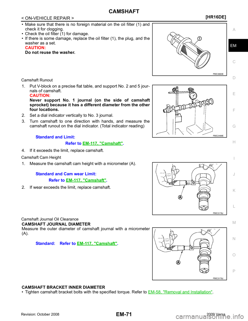
EM
NP
O
• Make sure that there is no foreign material on the oil filter (1) and
check it for clogging.
• Check the oil filter (1) for damage.
• If there is some damage, replace t he oil filter (1), the plug, and the
washer as a set.
CAUTION:
Do not reuse the washer.
Camshaft Runout 1. Put V-block on a precise flat table, and support No. 2 and 5 jour- nals of camshaft.
CAUTION:
Never support No. 1 journal (on the side of camshaft
sprocket) because it has a different diameter from the other
four locations.
2. Set a dial indicator vertically to No. 3 journal.
3. Turn camshaft to one direction with hands, and measure the camshaft runout on the dial indicator. (Total indicator reading)
4. If it exceeds the limit, replace camshaft.
Camshaft Cam Height 1. Measure the camshaft cam height with a micrometer (A).
2. If wear exceeds the limit, replace camshaft.
Camshaft Journa l Oil Clearance
CAMSHAFT JOURNAL DIAMETER
Measure the outer diameter of camshaft journal with a micrometer
(A).
CAMSHAFT BRACKET INNER DIAMETER
• Tighten camshaft bracket bolts with the specified torque. Refer to EM-58, " Removal and Installation " .Camshaft " .
Camshaft " .
Camshaft " .