height NISSAN TIIDA 2009 Service Owner's Guide
[x] Cancel search | Manufacturer: NISSAN, Model Year: 2009, Model line: TIIDA, Model: NISSAN TIIDA 2009Pages: 4331, PDF Size: 58.04 MB
Page 3023 of 4331
Exploded View " .
2. Remove valve lifters. Refer to EM-58, " Exploded View " .
3. Rotate crankshaft, and set piston whose valve oil seal is to be removed to TDC. This will prevent valve from dropping into cylinder.
CAUTION:
When rotating crankshaft, be careful to avo id scarring front cover with timing chain.
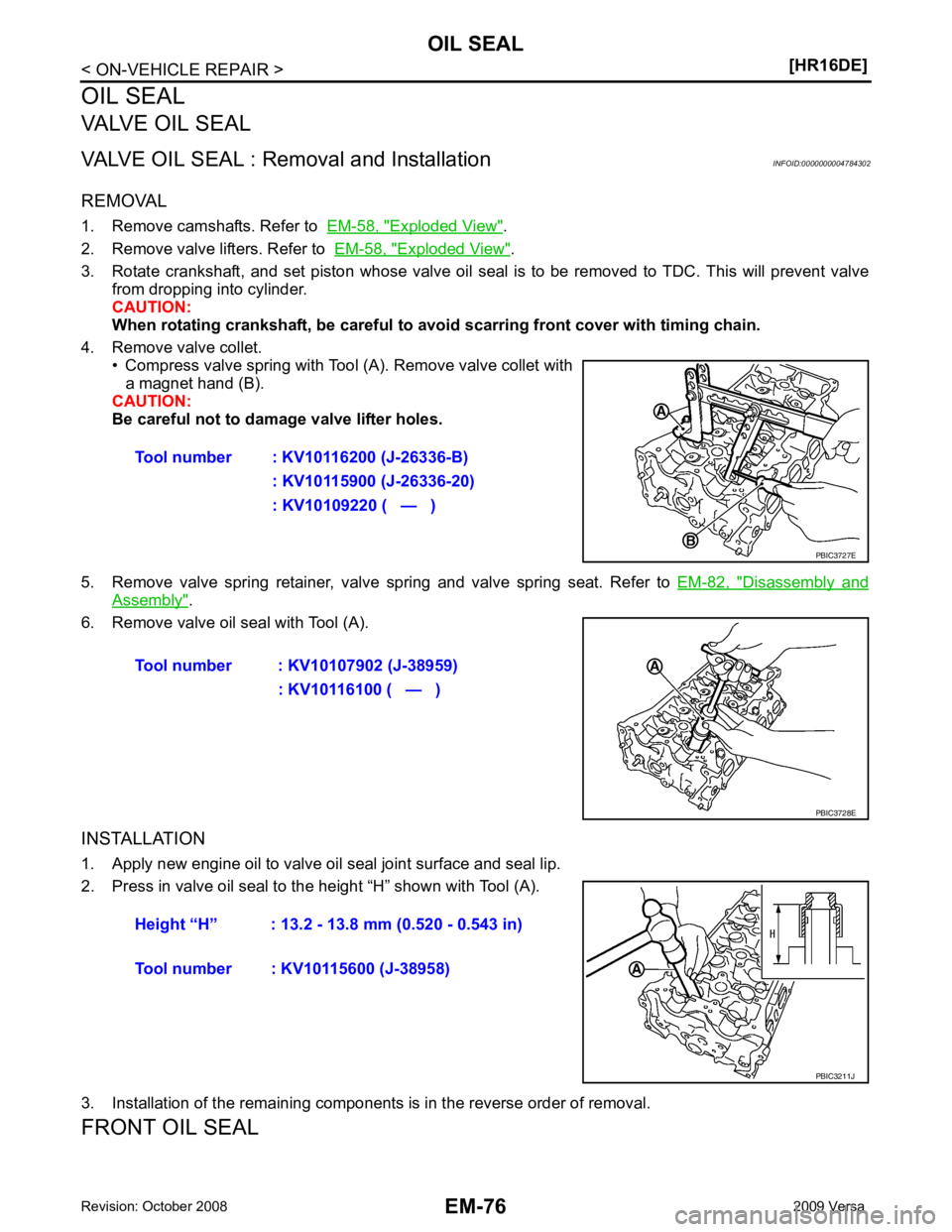
4. Remove valve collet. • Compress valve spring with Tool (A). Remove valve collet witha magnet hand (B).
CAUTION:
Be careful not to damage valve lifter holes.
5. Remove valve spring retainer, valve spring and valve spring seat. Refer to EM-82, " Disassembly and
Assembly " .
6. Remove valve oil seal with Tool (A).
INSTALLATION
1. Apply new engine oil to valve oil seal joint surface and seal lip.
2. Press in valve oil seal to the height “H” shown with Tool (A).
3. Installation of the remaining components is in the reverse order of removal.
FRONT OIL SEAL Tool number : KV10116200 (J-26336-B)
: KV10115900 (J-26336-20)
: KV10109220 ( — )
Page 3024 of 4331
EM
NP
O
FRONT OIL SEAL : Remo
val and Installation INFOID:0000000004784303
REMOVAL 1. Remove the following parts: • Front fender protector (RH): Refer to EI-24, " Removal and Installation " .
• Drive belt: Refer to EM-15, " Removal and Installation " .
• Crankshaft pulley: Refer to EM-49, " Exploded View " .
2. Remove front oil seal using a suitable tool. CAUTION:
Be careful not to damage fron t timing chain case and crankshaft.
INSTALLATION 1. Apply new engine oil to both oil seal lip and dust seal lip of new front oil seal.
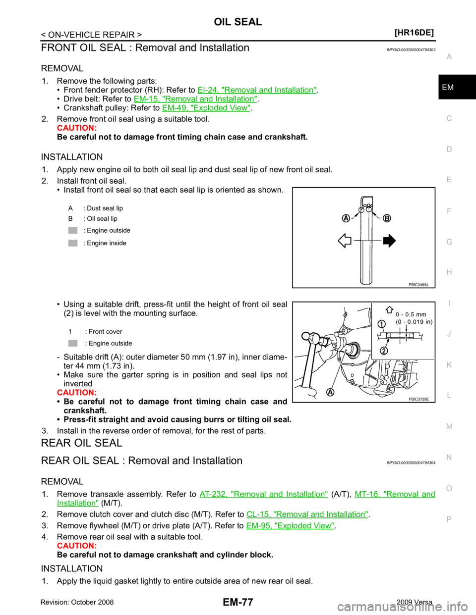
2. Install front oil seal. • Install front oil seal so that each seal lip is oriented as shown.
• Using a suitable drift, press-fit until the height of front oil seal (2) is level with the mounting surface.
- Suitable drift (A): outer diameter 50 mm (1.97 in), inner diame- ter 44 mm (1.73 in).
• Make sure the garter spring is in position and seal lips not
inverted
CAUTION:
• Be careful not to damage front timing chain case and
crankshaft.
• Press-fit straight and avoid cau sing burrs or tilting oil seal.
3. Install in the reverse order of removal, for the rest of parts.
REAR OIL SEAL
REAR OIL SEAL : Removal and Installation INFOID:0000000004784304
REMOVAL 1. Remove transaxle assembly. Refer to AT-232, " Removal and Installation " (A/T),
MT-16, " Removal and
Installation " (M/T).
2. Remove clutch cover and clutch disc (M/T). Refer to CL-15, " Removal and Installation " .
3. Remove flywheel (M/T) or drive plate (A/T). Refer to EM-95, " Exploded View " .
4. Remove rear oil seal with a suitable tool. CAUTION:
Be careful not to damage crankshaft and cylinder block.
INSTALLATION 1. Apply the liquid gasket lightly to entire outside area of new rear oil seal. A : Dust seal lip
B : Oil seal lip
: Engine outside
: Engine inside
Page 3032 of 4331
EM
NP
O
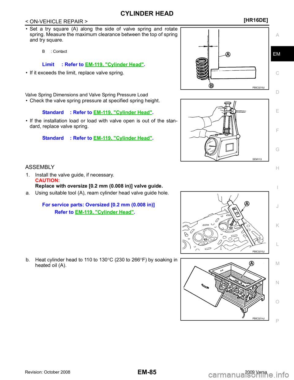
• Set a try square (A) along the side of valve spring and rotate
spring. Measure the maximum clearance between the top of spring
and try square.
• If it exceeds the limit, replace valve spring.
Valve Spring Dimensions and Valve Spring Pressure Load • Check the valve spring pressure at specified spring height.
• If the installation load or load with valve open is out of the stan- dard, replace valve spring.
ASSEMBLY 1. Install the valve guide, if necessary. CAUTION:
Replace with oversize [0.2 mm (0.008 in)] valve guide.
a. Using suitable tool (A), ream cylinder head valve guide hole.
b. Heat cylinder head to 110 to 130 °C (230 to 266 °F) by soaking in
heated oil (A). B : Contact
Limit : Refer to EM-119, " Cylinder Head " .
Cylinder Head " .
Standard : Refer to EM-119, " Cylinder Head " .
Cylinder Head " .
PBIC3214J
Page 3034 of 4331
![NISSAN TIIDA 2009 Service Owners Guide CYLINDER HEAD
EM-87
< ON-VEHICLE REPAIR >
[HR16DE] C
D E
F
G H
I
J
K L
M A EM
NP
O
d. Using suitable tool or valve seat grinder, finish seat to the speci-
fied dimensions. Refer to EM-119, " Cylinder](/img/5/57398/w960_57398-3033.png "NISSAN TIIDA 2009 Service Owners Guide CYLINDER HEAD
EM-87
< ON-VEHICLE REPAIR >
[HR16DE] C
D E
F
G H
I
J
K L
M A EM
NP
O
d. Using suitable tool or valve seat grinder, finish seat to the speci-
fied dimensions. Refer to EM-119, \" Cylinder")
CYLINDER HEAD
EM-87
< ON-VEHICLE REPAIR >
[HR16DE] C
D E
F
G H
I
J
K L
M A EM
NP
O
d. Using suitable tool or valve seat grinder, finish seat to the speci-
fied dimensions. Refer to EM-119, " Cylinder Head " .
CAUTION:
When using the valve seat cutt er, firmly grip cutter handle
with both hands. Then, press on the contacting surface all
around the circumference to cu t in a single drive. Improper
pressure on with cutter or cu tting many different times may
result in stage valve seat.
e. Using compound, grind to adjust valve fitting.
f. Check again for normal contact. Refer to EM-82, " Disassembly and Assembly " .
3. Install valve oil seal. • Install with Tool (A) to match dimension as shown.
4. Install valve spring seat.
5. Install valve. • Install larger diameter to intake side.
6. Install valve spring. NOTE:
It can be installed in either direction.
7. Install valve spring retainer.
8. Install valve collet. • Compress valve spring with Tool (A). Install valve collet with amagnet hand (B).
CAUTION:
Be careful not to damage valve lifter holes.
• Tap valve stem edge lightly with a plastic hammer after instal-
lation to check its installed condition.
9. Install valve lifter.
10. Install spark plug with a suitable tool. SEM934C
Height “H” : 13.2 - 13.8 mm (0.520 - 0.543 in)
Tool number : KV10115600 (J-38958) PBIC3211J
Tool number : KV10116200 (J-26336-B)
: KV10115900 (J-26336-20)
: KV10109220 ( — ) PBIC3727E
Page 3056 of 4331
EM
NP
O
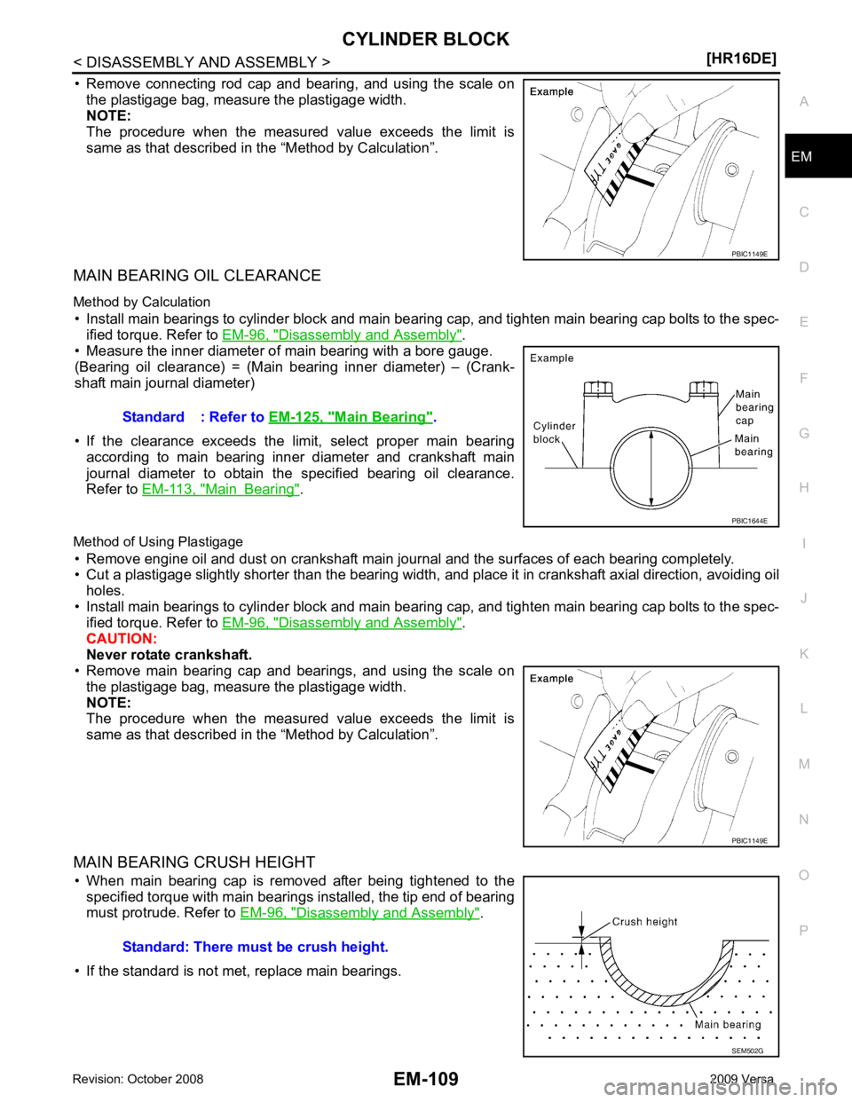
• Remove connecting rod cap and bearing, and using the scale on
the plastigage bag, measure the plastigage width.
NOTE:
The procedure when the measured value exceeds the limit is
same as that described in the “Method by Calculation”.
MAIN BEARING OIL CLEARANCE
Method by Calculation • Install main bearings to cylinder block and main bearing cap, and tighten main bearing cap bolts to the spec- ified torque. Refer to EM-96, " Disassembly and Assembly " .
• Measure the inner diameter of main bearing with a bore gauge.
(Bearing oil clearance) = (Main bearing inner diameter) – (Crank-
shaft main journal diameter)
• If the clearance exceeds the limit, select proper main bearing according to main bearing inner diameter and crankshaft main
journal diameter to obtain the specified bearing oil clearance.
Refer to EM-113, " Main Bearing " .
Method of Using Plastigage • Remove engine oil and dust on crankshaft main journal and the surfaces of each bearing completely.
• Cut a plastigage slightly shorter than the bearing width, and place it in crankshaft axial direction, avoiding oil
holes.
• Install main bearings to cylinder block and main bearing cap, and tighten main bearing cap bolts to the spec- ified torque. Refer to EM-96, " Disassembly and Assembly " .
CAUTION:
Never rotate crankshaft.
• Remove main bearing cap and bearings, and using the scale on
the plastigage bag, measure the plastigage width.
NOTE:
The procedure when the measured value exceeds the limit is
same as that described in the “Method by Calculation”.
MAIN BEARING CRUSH HEIGHT • When main bearing cap is removed after being tightened to the specified torque with main bearings installed, the tip end of bearing
must protrude. Refer to EM-96, " Disassembly and Assembly " .
• If the standard is not met, replace main bearings. Main Bearing " .
Page 3057 of 4331
![NISSAN TIIDA 2009 Service Owners Guide EM-110< DISASSEMBLY AND ASSEMBLY >
[HR16DE]
CYLINDER BLOCK
CONNECTING ROD BEARING CRUSH HEIGHT
• When connecting rod bearing cap is removed after being tightened to the specified torque with co](/img/5/57398/w960_57398-3056.png "NISSAN TIIDA 2009 Service Owners Guide EM-110< DISASSEMBLY AND ASSEMBLY >
[HR16DE]
CYLINDER BLOCK
CONNECTING ROD BEARING CRUSH HEIGHT
• When connecting rod bearing cap is removed after being tightened to the specified torque with co")
EM-110< DISASSEMBLY AND ASSEMBLY >
[HR16DE]
CYLINDER BLOCK
CONNECTING ROD BEARING CRUSH HEIGHT
• When connecting rod bearing cap is removed after being tightened to the specified torque with connecting rod bearings installed, the
tip end of bearing must protrude. Refer to EM-96, " Disassembly
and Assembly " .
• If the standard is not met, replace connecting rod bearings.
MAIN BEARING CAP BOLT OUTER DIAMETER
• Measure the outer diameters (“d 1”, “d 2”) at two positions as shown.
• If reduction appears in a position other than “d 2 ”, regard it as “d 2”.
• If it exceeds the limit (a large difference in dimensions), replace main bearing cap bolt with a new one.
CONNECTING ROD CAP BOLT OUTER DIAMETER
• Measure the outer diameter “d” at position as shown.
• If reduction appears in a position other than “d”, regard it as “d”.
• When “d” falls below the limit (when it becomes thinner), replace connecting rod cap bolt with a new one.
FLYWHEEL DEFLECTION
• Measure the deflection of flywheel contact surface to clutch with a
dial indicator.
• If measured value is out of the standard, replace flywheel. Standard: There must be crush height. PBIC1646E
Limit (“d
1”–“d 2”): 0.2 mm (0.008 in) PBIC3768E
Limit: 7.75 mm (0.3051 in)
PBIC3769E
Standard : 0.25 mm (0.0098 in) or less.
PBIC2646E
Page 3064 of 4331
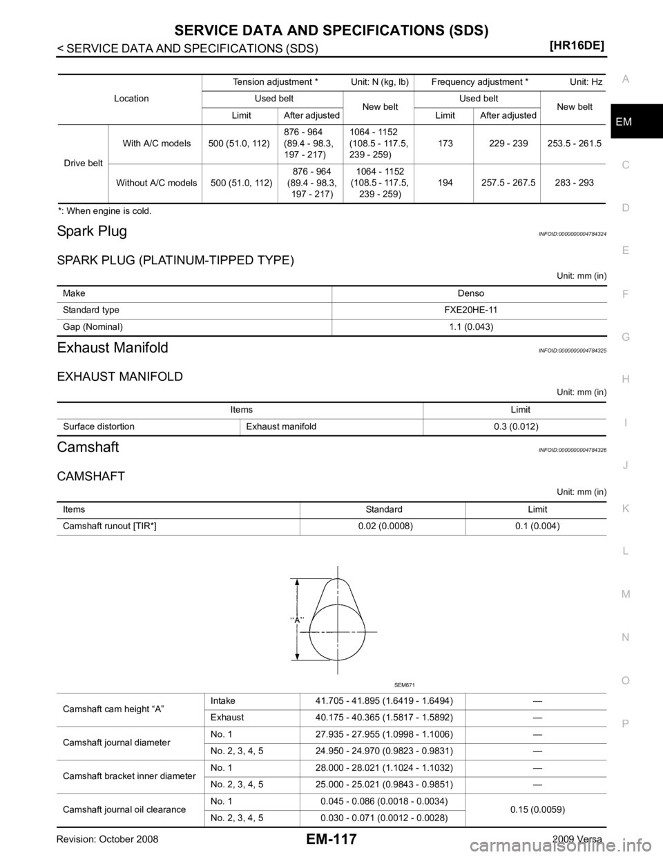
EM
NP
O
*: When engine is cold.
Spark Plug INFOID:0000000004784324
SPARK PLUG (PLATINUM-TIPPED TYPE) Unit: mm (in)
Exhaust Manifold INFOID:0000000004784325
EXHAUST MANIFOLD Unit: mm (in)
Camshaft INFOID:0000000004784326
CAMSHAFT Unit: mm (in)
Location
Tension adjustment * Unit: N (kg, lb) Frequency adjustment * Unit: Hz
Used belt New beltUsed belt
New belt
Limit After adjusted Limit After adjusted
Drive belt With A/C models 500 (51.0, 112)
876 - 964
(89.4 - 98.3,
197 - 217) 1064 - 1152
(108.5 - 117.5,
239 - 259) 173 229 - 239 253.5 - 261.5
Without A/C models 500 (51.0, 112) 876 - 964
(89.4 - 98.3, 197 - 217) 1064 - 1152
(108.5 - 117.5, 239 - 259) 194 257.5 - 267.5 283 - 293Make
Denso
Standard type FXE20HE-11
Gap (Nominal) 1.1 (0.043)Items Limit
Surface distortion Exhaust manifold 0.3 (0.012) Items
Standard Limit
Camshaft runout [TIR*] 0.02 (0.0008) 0.1 (0.004)
Camshaft cam height “A” Intake 41.705 - 41.895 (1.6419 - 1.6494) —
Exhaust 40.175 - 40.365 (1.5817 - 1.5892) —
Camshaft journal diameter No. 1 27.935 - 27.955 (1.0998 - 1.1006) —
No. 2, 3, 4, 5 24.950 - 24.970 (0.9823 - 0.9831) —
Camshaft bracket inner diameter No. 1 28.000 - 28.021 (1.1024 - 1.1032) —
No. 2, 3, 4, 5 25.000 - 25.021 (0.9843 - 0.9851) —
Camshaft journal oil clearance No. 1 0.045 - 0.086 (0.0018 - 0.0034)
0.15 (0.0059)
No. 2, 3, 4, 5 0.030 - 0.071 (0.0012 - 0.0028)
Page 3066 of 4331
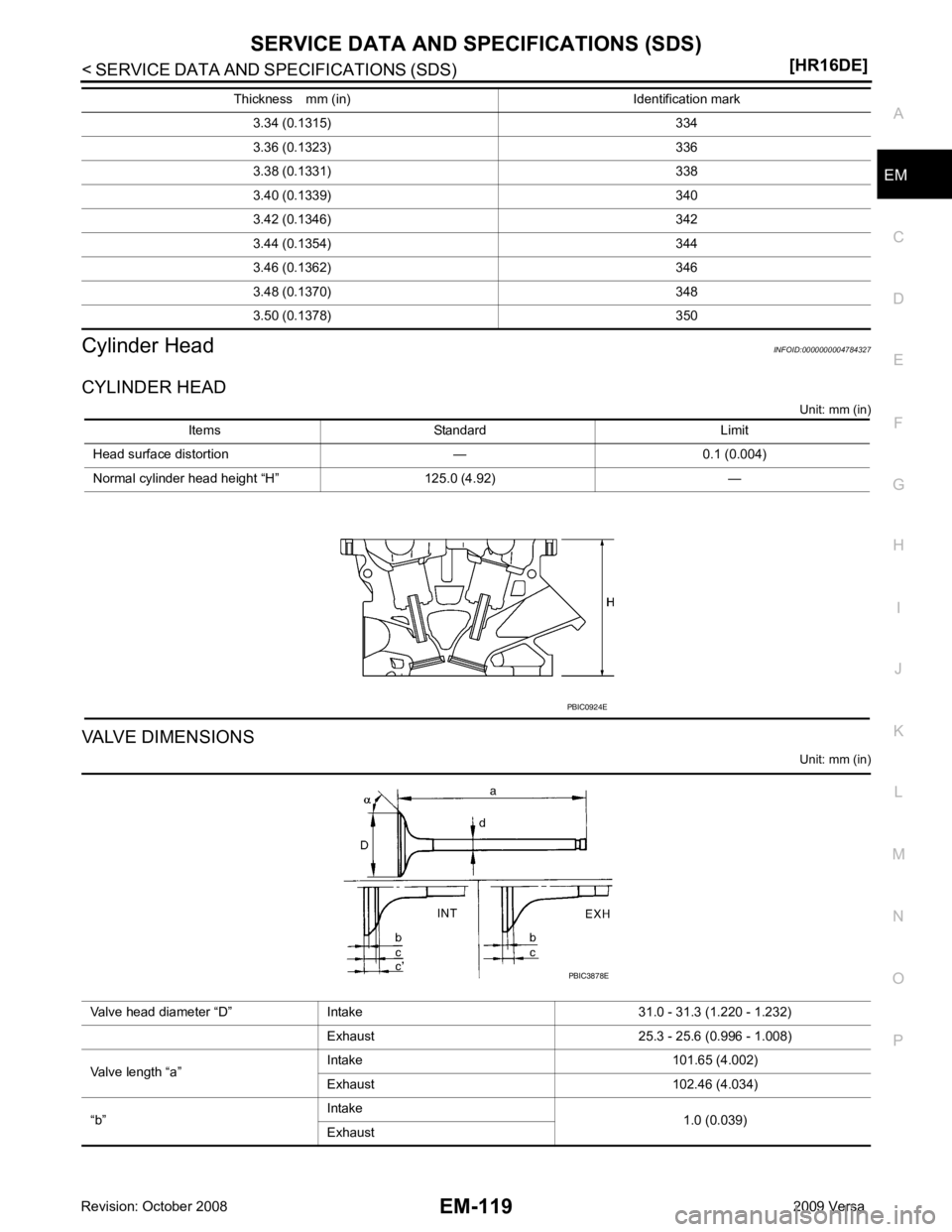
EM
NP
O
Cylinder Head
INFOID:0000000004784327
CYLINDER HEAD Unit: mm (in)
VALVE DIMENSIONS Unit: mm (in)
3.34 (0.1315) 334
3.36 (0.1323) 336
3.38 (0.1331) 338
3.40 (0.1339) 340
3.42 (0.1346) 342
3.44 (0.1354) 344
3.46 (0.1362) 346
3.48 (0.1370) 348
3.50 (0.1378) 350
Thickness mm (in) Identification mark Items Standard Limit
Head surface distortion — 0.1 (0.004)
Normal cylinder head height “H” 125.0 (4.92) —
Page 3068 of 4331
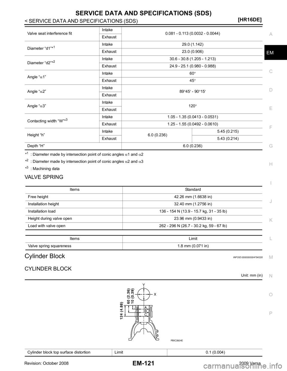
EM
NP
O
*
1
: Diameter made by intersection point of conic angles α1 and α2
* 2
: Diameter made by intersection point of conic angles α2 and α3
* 3
: Machining data
VALVE SPRING
Cylinder Block INFOID:0000000004784328
CYLINDER BLOCK Unit: mm (in)
Valve seat interference fit
Intake
0.081 - 0.113 (0.0032 - 0.0044)
Exhaust
Diameter “d1”* 1 Intake 29.0 (1.142)
Exhaust 23.0 (0.906)
Diameter “d2”* 2 Intake 30.6 - 30.8 (1.205 - 1.213)
Exhaust 24.9 - 25.1 (0.980 - 0.988)
Angle “ α1” Intake 60
°
Exhaust 45 °
Angle “ α2” Intake
89°45 ′ - 90 °15 ′
Exhaust
Angle “ α3” Intake
120°
Exhaust
Contacting width “W”* 3Intake 1.05 - 1.35 (0.0413 - 0.0531)
Exhaust 1.25 - 1.55 (0.0492 - 0.0610)
Height “h” Intake
6.0 (0.236) 5.45 (0.215)
Exhaust 5.43 (0.214)
Depth “H” 6.0 (0.236)Items Standard
Free height 42.26 mm (1.6638 in)
Installation height 32.40 mm (1.2756 in)
Installation load 136 - 154 N (13.9 - 15.7 kg, 31 - 35 lb)
Height during valve open 23.96 mm (0.9433 in)
Load with valve open 262 - 296 N (26.7 - 30.2 kg, 59 - 67 lb)
Items Limit
Valve spring squareness 1.8 mm (0.071 in) Cylinder block top surface distortion Limit 0.1 (0.004)
Page 3129 of 4331
![NISSAN TIIDA 2009 Service Owners Guide EM-182< SERVICE INFORMATION >
[MR18DE]
OIL SEAL
OIL SEAL
Removal and Installation of Valve Oil Seal INFOID:0000000004307147
REMOVAL
1. Remove camshafts. Refer to EM-170, " Component " .
2. Remove va](/img/5/57398/w960_57398-3128.png "NISSAN TIIDA 2009 Service Owners Guide EM-182< SERVICE INFORMATION >
[MR18DE]
OIL SEAL
OIL SEAL
Removal and Installation of Valve Oil Seal INFOID:0000000004307147
REMOVAL
1. Remove camshafts. Refer to EM-170, \" Component \" .
2. Remove va")
EM-182< SERVICE INFORMATION >
[MR18DE]
OIL SEAL
OIL SEAL
Removal and Installation of Valve Oil Seal INFOID:0000000004307147
REMOVAL
1. Remove camshafts. Refer to EM-170, " Component " .
2. Remove valve lifters. Refer to EM-170 .
3. Rotate crankshaft, and set piston whose valve oil seal is to be removed to TDC. This will prevent valve from dropping into cylinder.
CAUTION:
When rotating crankshaft, be careful to avo id scarring front cover with timing chain.
4. Remove valve collet. • Compress valve spring using Tool (A). Remove valve collet
with a suitable magnet hand (B).
CAUTION:
When working, be careful not to damage valve lifter holes.
5. Remove valve spring retainer, valve spring and valve spring seat.
6. Remove valve oil seal using Tool (A).
INSTALLATION
1. Apply new engine oil to valve oil seal joint surface and seal lip.
2. Press in valve oil seal to the height (H) shown using Tool (A).
3. Installation of the remaining components is in the reverse order of removal.
Removal and Installation of Front Oil Seal INFOID:0000000004307148
REMOVAL
1. Remove the following parts. • Front fender protector (RH); Refer to EI-24 .
Tool number : KV101092S0 (J-26336-B)
PBIC3727E
Tool number :KV10107902 (J-38959)
PBIC3728E
Height (H) : 15.1 - 15.7 mm (0.594 - 0.618 in)
Tool number : KV10115600 (J-38958) PBIC3211J