Cooling fan NISSAN TIIDA 2009 Service Repair Manual
[x] Cancel search | Manufacturer: NISSAN, Model Year: 2009, Model line: TIIDA, Model: NISSAN TIIDA 2009Pages: 4331, PDF Size: 58.04 MB
Page 895 of 4331

CO
N
O P
CONTENTS
ENGINE COOLING SYSTEM
HR16DE
PRECAUTION ....... ........................................
3
PRECAUTIONS .............................................. .....3
Precaution for Supplemental Restraint System
(SRS) "AIR BAG" and "SEAT BELT PRE-TEN-
SIONER" ............................................................. ......
3
Precaution Necessary fo r Steering Wheel Rota-
tion After Battery Disconnect ............................... ......
3
Precaution for Liquid Gasket ............................... ......4
PREPARATION .... ........................................5
PREPARATION .............................................. .....5
Special Service Tool ........................................... ......5
Commercial Service Tool .................................... ......5
SYMPTOM DIAGNOSIS ..... ..........................7
OVERHEATING CAUSE ANALYSIS ............. .....7
Troubleshooting Chart ..... ..........................................7
FUNCTION DIAGNOSIS .. .............................9
DESCRIPTION ............................................... .....9
Engine Cooling System ....................................... ......9
Engine Cooling System Schematic ..................... ....10
ON-VEHICLE MAINTENA NCE ....................11
ENGINE COOLANT ....................................... ....11
Inspection ............................................................ ....11
Changing Engine Coolant ................................... ....11
RADIATOR ..................................................... ....14
Checking Radiator Cap ....................................... ....14
Checking Radiator ............................................... ....14
ON-VEHICLE REPAIR .... .............................16
RADIATOR ..................................................... ....16 Component ..........................................................
....16
Removal and Installation ..................................... ....16
COOLING FAN .................................................. 18
Component (Models with A/C) ............................. ....18
Component (Models without A/C) ........................ ....18
Removal and Installation ..................................... ....19
WATER PUMP .................................................. 20
Exploded View ..................................................... ....20
Removal and Installation ..................................... ....20
Inspection ............................................................ ....21
THERMOSTAT .................................................. 22
Exploded View ..................................................... ....22
Removal and Installation ..................................... ....22
Inspection ............................................................ ....23
WATER OUTLET .............................................. 24
Exploded View ..................................................... ....24
Removal and Installation ..................................... ....24
Inspection ............................................................ ....25
DISASSEMBLY AND AS SEMBLY ..............26
COOLING FAN .................................................. 26
Disassembly and Assembly ................................. ....26
SERVICE DATA AND SPECIFICATIONS
(SDS) ............... .............................................
27
SERVICE DATA AND SPECIFICATIONS
(SDS) ................................................................. 27
Periodical Maintenance Specification .................. ....27
Radiator ............................................................... ....27
Thermostat .......................................................... ....27
MR18DE
SERVICE INFORMATION .. .........................28
PRECAUTIONS ................................................. 28
Page 901 of 4331

CO
NP
O
SYMPTOM DIAGNOSIS
OVERHEATING CAUSE ANALYSIS
Troubleshooting Chart INFOID:0000000004784346
Symptom Check items
Cooling sys-
tem parts
malfunction Poor heat transfer
Water pump malfunction Worn or loose drive belt
—
Thermostat stuck closed —
Damaged fins Dust contamination or pa-
per clogging
Physical damage
Clogged radiator cooling
tube Excess foreign material
(rust, dirt, sand, etc.)
Reduced air flow Cooling fan does not oper-
ate
Fan assembly —
High resistance to fan rota-
tion
Damaged fan blades
Damaged radiator shroud — — —
Improper engine coolant
mixture ratio — — —
Poor engine coolant quality — Engine coolant viscosity —
Insufficient engine coolant Engine coolant leaks Cooling hose
Loose clamp
Cracked hose
Water pump Poor sealing
Reservoir tank cap Loose
Poor sealing
Radiator O-ring for damage, deterio-
ration or improper fitting
Cracked radiator tank
Cracked radiator core
Reservoir tank Cracked reservoir tank
Overflowing reservoir tank Exhaust gas leaks into cool-
ing system Cylinder head deterioration
Cylinder head gasket deteri-
oration
Page 913 of 4331
CO
NP
O
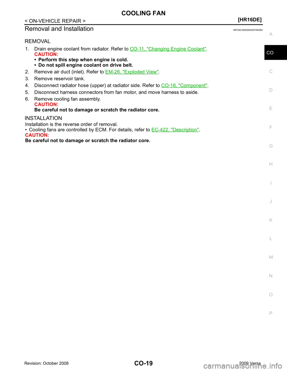
Removal and Installation
INFOID:0000000004784360
REMOVAL 1. Drain engine coolant from radiator. Refer to CO-11, " Changing Engine Coolant " .
CAUTION:
• Perform this step when engine is cold.
• Do not spill engine coolant on drive belt.
2. Remove air duct (inlet). Refer to EM-26, " Exploded View " .
3. Remove reservoir tank.
4. Disconnect radiator hose (upper) at radiator side. Refer to CO-16, " Component " .
5. Disconnect harness connectors from fan motor, and move harness to aside.
6. Remove cooling fan assembly. CAUTION:
Be careful not to damage or scratch the radiator core.
INSTALLATION Installation is the reverse order of removal.
• Cooling fans are controlled by ECM. For details, refer to EC-422, " Description " .
CAUTION:
Be careful not to damage or scratch the radiator core.
Page 934 of 4331
![NISSAN TIIDA 2009 Service Repair Manual CO-40< SERVICE INFORMATION >
[MR18DE]
RADIATOR
Checking Radiator Cap INFOID:0000000004305238
• Check valve seat of radiator cap.
- Check if valve seat is swollen to the extent that the e](/img/5/57398/w960_57398-933.png "NISSAN TIIDA 2009 Service Repair Manual CO-40< SERVICE INFORMATION >
[MR18DE]
RADIATOR
Checking Radiator Cap INFOID:0000000004305238
• Check valve seat of radiator cap.
- Check if valve seat is swollen to the extent that the e")
CO-40< SERVICE INFORMATION >
[MR18DE]
RADIATOR
Checking Radiator Cap INFOID:0000000004305238
• Check valve seat of radiator cap.
- Check if valve seat is swollen to the extent that the edge of the plunger cannot be seen when watching it vertically from the top.
- Check if valve seat has no soil and damage.
• Pull negative-pressure valve to open it, and make sure that it is completely closed when released.
- Make sure that there is no dirt or damage on the valve seat of radi-
ator cap negative-pressure valve.
- Make sure that the valve operates properly in the opening and closing conditions.
• Check radiator cap relief pressure using Tool.
- When connecting the radiator cap to the tester, apply water or coolant to the cap seal surface.
- Replace the radiator cap if ther e is an abnormality in the negative-
pressure valve, or if the open-valve pr essure is outside of the standard values.
• Replace radiator cap if there it does not comply to specifications to the above three checks.
CAUTION:
When installing radiator cap, thoroughly wipe out the radiator filler neck to remove any waxy residue
or foreign material.
Checking Radiator INFOID:0000000004305239
Check radiator for mud or clogging. If necessary, clean radiator as follows.
• Be careful not to bend or damage radiator fins.
• When radiator is cleaned without removal, remove all surrounding parts such as cooling fan, radiator shroud and horns. Then tape harness and connectors to prevent water from entering.
1. Apply water by hose to the back side of the radiator core vertically downward.
2. Apply water again to all radiator core surface once per minute.
3. Stop washing if any stains no longer flow out from radiator.
4. Blow air into the back side of radiator core vertically downward. • Use compressed air lower than 490 kPa (4.9 bar, 5 kg/cm 2
, 71 psi) and keep distance more than 30 cm
(11.8 in).
5. Blow air again into all the radiator core surfaces once per minute until no water sprays out. PBIC2816E
SMA967B
Tool number : EG17650301 (J-33984-A)
Standard: 78 – 98 kPa (0.78 - 0.98 bar, 0.8 – 1.0 kg/cm 2
, 11
– 14 psi)
Limit: 59 kPa (0.59 bar, 0.6 kg/cm 2
, 9 psi) WBIA0570E
Page 935 of 4331
![NISSAN TIIDA 2009 Service Repair Manual COOLING FAN
CO-41
< SERVICE INFORMATION >
[MR18DE] C
D E
F
G H
I
J
K L
M A CO
NP
O
COOLING FAN
Component (Models with A/C) INFOID:0000000004305240
Component (Models without A/C) INFOID:000000000430524](/img/5/57398/w960_57398-934.png "NISSAN TIIDA 2009 Service Repair Manual COOLING FAN
CO-41
< SERVICE INFORMATION >
[MR18DE] C
D E
F
G H
I
J
K L
M A CO
NP
O
COOLING FAN
Component (Models with A/C) INFOID:0000000004305240
Component (Models without A/C) INFOID:000000000430524")
COOLING FAN
CO-41
< SERVICE INFORMATION >
[MR18DE] C
D E
F
G H
I
J
K L
M A CO
NP
O
COOLING FAN
Component (Models with A/C) INFOID:0000000004305240
Component (Models without A/C) INFOID:0000000004305241
1. Fan motor cover 2. Fan motor 3. Cooling fan control module
4. Washer 5. Fan shroud 6. Washer
7. Cooling fan A. Apply on fan motor shaft Front PBIC4538E
1. Fan motor 2. Fan shroud 3. Cooling fan
A. Apply on fan motor shaft Front WBIA0786E
Page 936 of 4331
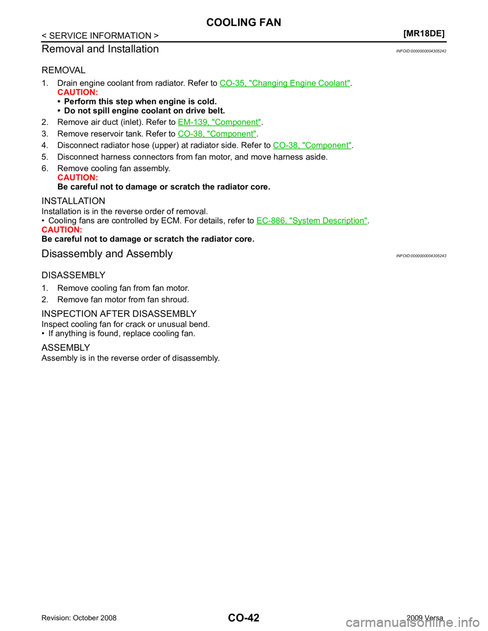
Changing Engine Coolant " .
CAUTION:
• Perform this step when engine is cold.
• Do not spill engine coolant on drive belt.
2. Remove air duct (inlet). Refer to EM-139, " Component " .
3. Remove reservoir tank. Refer to CO-38, " Component " .
4. Disconnect radiator hose (upper) at radiator side. Refer to CO-38, " Component " .
5. Disconnect harness connectors from fan motor, and move harness aside.
6. Remove cooling fan assembly. CAUTION:
Be careful not to damage or scratch the radiator core.
INSTALLATION
Installation is in the reverse order of removal.
• Cooling fans are controlled by ECM. For details, refer to EC-886, " System Description " .
CAUTION:
Be careful not to damage or scratch the radiator core.
Disassembly and Assembly INFOID:0000000004305243
DISASSEMBLY
1. Remove cooling fan from fan motor.
2. Remove fan motor from fan shroud.
INSPECTION AFTER DISASSEMBLY
Inspect cooling fan for crack or unusual bend.
• If anything is found, replace cooling fan.
ASSEMBLY
Assembly is in the reverse order of disassembly.
Page 1397 of 4331
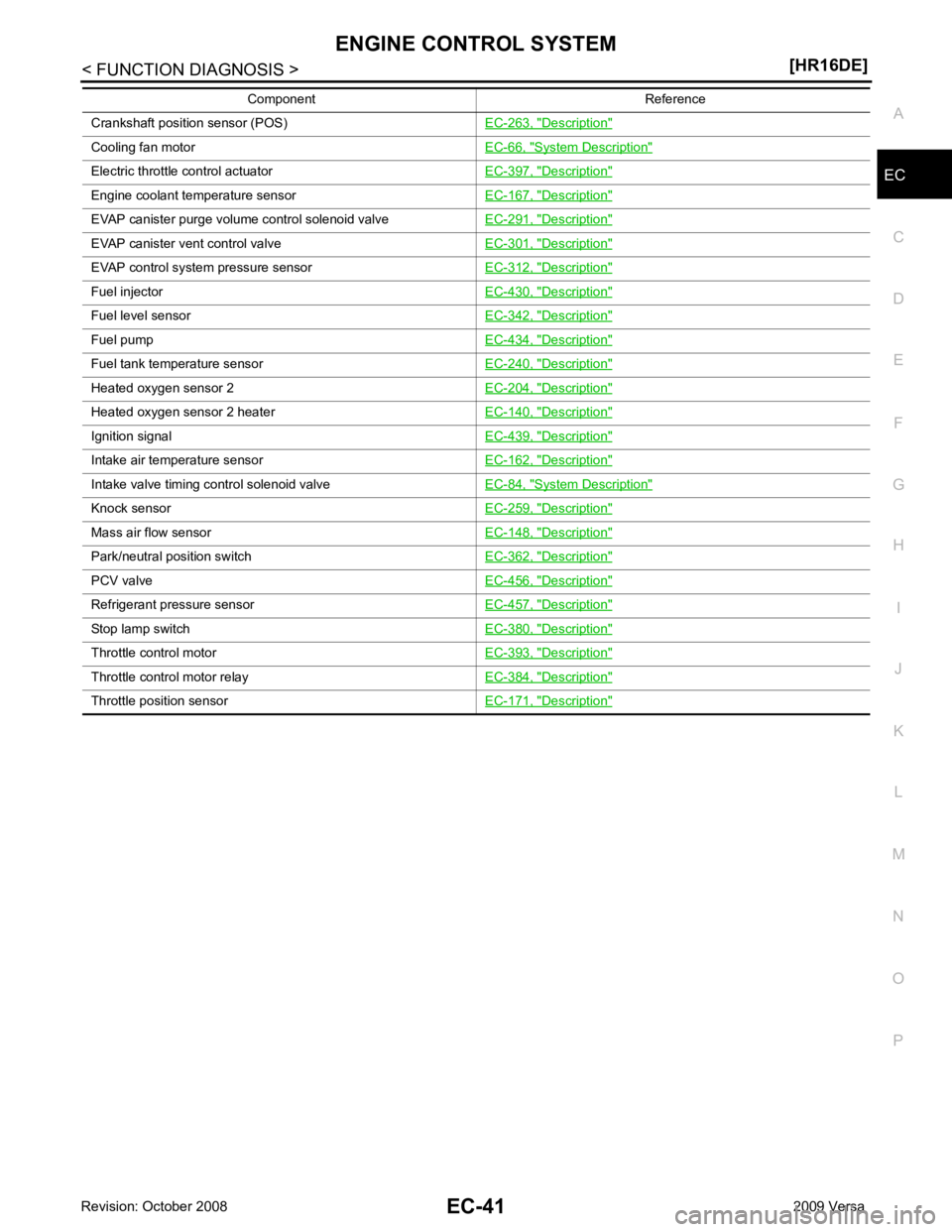
EC
NP
O
Crankshaft position sensor (POS)
EC-263, " Description "
Cooling fan motor
EC-66, " System Description "
Electric throttle control actuator
EC-397, " Description "
Engine coolant temperature sensor
EC-167, " Description "
EVAP canister purge volume control solenoid valve
EC-291, " Description "
EVAP canister vent control valve
EC-301, " Description "
EVAP control system pressure sensor
EC-312, " Description "
Fuel injector
EC-430, " Description "
Fuel level sensor
EC-342, " Description "
Fuel pump
EC-434, " Description "
Fuel tank temperature sensor
EC-240, " Description "
Heated oxygen sensor 2
EC-204, " Description "
Heated oxygen sensor 2 heater
EC-140, " Description "
Ignition signal
EC-439, " Description "
Intake air temperature sensor
EC-162, " Description "
Intake valve timing control solenoid valve
EC-84, " System Description "
Knock sensor
EC-259, " Description "
Mass air flow sensor
EC-148, " Description "
Park/neutral position switch
EC-362, " Description "
PCV valve
EC-456, " Description "
Refrigerant pressure sensor
EC-457, " Description "
Stop lamp switch
EC-380, " Description "
Throttle control motor
EC-393, " Description "
Throttle control motor relay
EC-384, " Description "
Throttle position sensor
EC-171, " Description "Component Reference
Page 1401 of 4331
![NISSAN TIIDA 2009 Service Repair Manual MULTIPORT FUEL INJECTION SYSTEM
EC-45
< FUNCTION DIAGNOSIS >
[HR16DE] C
D E
F
G H
I
J
K L
M A EC
NP
O
Component Parts Location
INFOID:0000000004780012
1. Ignition coil (with power transistor) and spa](/img/5/57398/w960_57398-1400.png "NISSAN TIIDA 2009 Service Repair Manual MULTIPORT FUEL INJECTION SYSTEM
EC-45
< FUNCTION DIAGNOSIS >
[HR16DE] C
D E
F
G H
I
J
K L
M A EC
NP
O
Component Parts Location
INFOID:0000000004780012
1. Ignition coil (with power transistor) and spa")
MULTIPORT FUEL INJECTION SYSTEM
EC-45
< FUNCTION DIAGNOSIS >
[HR16DE] C
D E
F
G H
I
J
K L
M A EC
NP
O
Component Parts Location
INFOID:0000000004780012
1. Ignition coil (with power transistor) and spark plug 2. Intake valve timing control solenoid
valve 3. Refrigerant pressure sensor
4. Knock sensor 5. Fuel injector 6. Cooling fan motor
7. Camshaft position sensor (PHASE) 8. IPDM E/R 9. ECM
10. Mass air flow sensor (with intake air temperature sensor) 11. Engine coolant temperature sensor 12. Electric throttle control actuator
(with built in throttle position sensor
and throttle control motor)
13. EVAP canister purge volume control solenoid valve PBIB2939E
Page 1405 of 4331
![NISSAN TIIDA 2009 Service Repair Manual MULTIPORT FUEL INJECTION SYSTEM
EC-49
< FUNCTION DIAGNOSIS >
[HR16DE] C
D E
F
G H
I
J
K L
M A EC
NP
O
Component Description INFOID:0000000004780013
1. Cooling fan motor harness connec-
tor 2. Cranksha](/img/5/57398/w960_57398-1404.png "NISSAN TIIDA 2009 Service Repair Manual MULTIPORT FUEL INJECTION SYSTEM
EC-49
< FUNCTION DIAGNOSIS >
[HR16DE] C
D E
F
G H
I
J
K L
M A EC
NP
O
Component Description INFOID:0000000004780013
1. Cooling fan motor harness connec-
tor 2. Cranksha")
MULTIPORT FUEL INJECTION SYSTEM
EC-49
< FUNCTION DIAGNOSIS >
[HR16DE] C
D E
F
G H
I
J
K L
M A EC
NP
O
Component Description INFOID:0000000004780013
1. Cooling fan motor harness connec-
tor 2. Crankshaft position sensor 3. Stop lamp switch
4. Brake pedal 5. Accelerator pedal position sensor harness connector6. Accelerator pedal position sensor
7. Accelerator pedal 8. Fuel level sensor unit and fuel pump harness connector (view with in-
spection hole cover removed) 9. Fuel pressure regulator
10. Fuel pump AWBIA0044ZZ
Component Reference
A/F sensor 1 EC-182, " Description "
Accelerator pedal position sensor
EC-399, " Description "
Camshaft position sensor (PHASE)
EC-268, " Description "
Crankshaft position sensor (POS)
EC-263, " Description "
Page 1408 of 4331
![NISSAN TIIDA 2009 Service Repair Manual EC-52< FUNCTION DIAGNOSIS >
[HR16DE]
ELECTRIC IGNITION SYSTEM
The knock sensor retard system is designed only for emergencies. The basic ignition timing is programmed
within the anti-k](/img/5/57398/w960_57398-1407.png "NISSAN TIIDA 2009 Service Repair Manual EC-52< FUNCTION DIAGNOSIS >
[HR16DE]
ELECTRIC IGNITION SYSTEM
The knock sensor retard system is designed only for emergencies. The basic ignition timing is programmed
within the anti-k")
EC-52< FUNCTION DIAGNOSIS >
[HR16DE]
ELECTRIC IGNITION SYSTEM
The knock sensor retard system is designed only for emergencies. The basic ignition timing is programmed
within the anti-knocking zone, if recommended fuel is used under dry conditions. The retard system does not
operate under normal driving conditions. If engine knocking occurs, the knock sensor monitors the condition.
The signal is transmitted to the ECM. The ECM retards the ignition timing to eliminate the knocking condition.
Component Parts Location INFOID:0000000004780016
1. Ignition coil (with power transistor) and spark plug 2. Intake valve timing control solenoid
valve 3. Refrigerant pressure sensor
4. Knock sensor 5. Fuel injector 6. Cooling fan motor
7. Camshaft position sensor (PHASE) 8. IPDM E/R 9. ECM
10. Mass air flow sensor (with intake air temperature sensor) 11. Engine coolant temperature sensor 12. Electric throttle control actuator
(with built in throttle position sensor
and throttle control motor)
13. EVAP canister purge volume control solenoid valve PBIB2939E