Master cylinder NISSAN TIIDA 2009 Service Repair Manual
[x] Cancel search | Manufacturer: NISSAN, Model Year: 2009, Model line: TIIDA, Model: NISSAN TIIDA 2009Pages: 4331, PDF Size: 58.04 MB
Page 801 of 4331

BR
N
O P
CONTENTS
BRAKE SYSTEM
SERVICE INFORMATION .. ..........................2
PRECAUTIONS .............................................. .....2
Precaution for Supplemental Restraint System
(SRS) "AIR BAG" and "SEAT BELT PRE-TEN-
SIONER" ............................................................. ......
2
Precaution Necessary fo r Steering Wheel Rota-
tion After Battery Disconnect ............................... ......
2
Precaution for Brake System .............................. ......3
PREPARATION .............................................. .....4
Special Service Tool ........................................... ......4
Commercial Service Tool .................................... ......4
NOISE, VIBRATION AND HARSHNESS
(NVH) TROUBLESHOOTING ........................ .....5
NVH Troubleshooting Chart ................................ ......5
BRAKE PEDAL .............................................. .....6
Inspection and Adjustment .................................. ......6
Removal and Installation ...........................................7
BRAKE FLUID .....................................................9
On Board Inspection ........................................... ......9
Drain and Refill .................................................... ......9
Bleeding Brake System ....................................... ......9
BRAKE TUBE AND HOSE ............................ ....11
Hydraulic Circuit .................................................. ....11
Front Brake Tube and Hose ................................ ....12
Rear Brake Tube and Hose ................................ ....12
Inspection After Installation ................................. ....13
DUAL PROPORTIONING VALVE ................. ....14
Removal and Installation .........................................14
Inspection ............................................................ ....14
BRAKE MASTER CY LINDER ........................ ....15
On-Board Inspection ........................................... ....15 Removal and Installation .....................................
....15
Disassembly and Assembly ................................. ....16
BRAKE BOOSTER ........................................... 20
On Board Inspection ............................................ ....20
Removal and Installation ..................................... ....21
VACUUM LINES ............................................... 23
Component .......................................................... ....23
Removal and Installation ..................................... ....23
Inspection ............................................................ ....23
FRONT DISC BRAKE ....................................... 25
On Board Inspection ............................................ ....25
Component .......................................................... ....25
Removal and Installation of Brake Pad ...................26
Removal and Installation of Brake Caliper Assem-
bly ........................................................................ ....
28
Disassembly and Assembly of Brake Caliper As-
sembly ................................................................. ....
29
Brake Burnishing Procedure ................................ ....32
REAR DRUM B RAKE ....................................... 33
Component .......................................................... ....33
Removal and Installation of Drum Brake Assembly ....34
Removal and Installation of Wheel Cylinder ........ ....37
Disassembly and Assembly of Wheel Cylinder ... ....37
SERVICE DATA AND SPECIFICATIONS
(SDS) ................................................................. 38
General Specification .......................................... ....38
Brake Pedal ......................................................... ....39
Check Valve ........................................................ ....39
Brake Booster ...................................................... ....40
Front Disc Brake .................................................. ....40
Rear Drum Brake ................................................. ....40
Page 803 of 4331
BR
N
O P
5. When the repair work is completed, return the ignition switch to the
″LOCK ″ position before connecting
the battery cables. (At this time, the steering lock mechanism will engage.)
6. Perform a self-diagnosis check of al l control units using CONSULT-III.
Precaution for Brake System INFOID:0000000004305887
• Refill using recommended brake fluid. Refer to MA-14 .
• Never reuse drained brake fluid.
• Be careful not to splash brake fluid on painted surfac e of body. If brake fluid is splashed on painted surfaces
of body immediately wipe it off with cloth and then wash it away with water.
• To clean or wash all parts of master cylinder, disc brake caliper and wheel cylinder, use new brake fluid.
• Never use mineral oils such as gasoline or kerosene. They will ruin rubber parts of the hydraulic system.
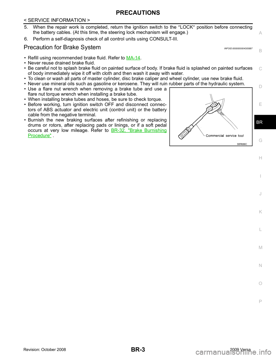
• Use a flare nut wrench when removing a brake tube and use a flare nut torque wrench when installing a brake tube.
• When installing brake tubes and hoses, be sure to check torque.
• Before working, turn igniti on switch OFF and disconnect connec-
tors of ABS actuator and electric unit (control unit) or the battery
cable from the negative terminal.
• Burnish the new braking surfaces after refinishing or replacing drums or rotors, after replacing p ads or linings, or if a soft pedal
occurs at very low mileage. Refer to BR-32, " Brake Burnishing
Procedure " .
Page 809 of 4331
BR
N
O P
BRAKE FLUID
On Board Inspection INFOID:0000000004305892
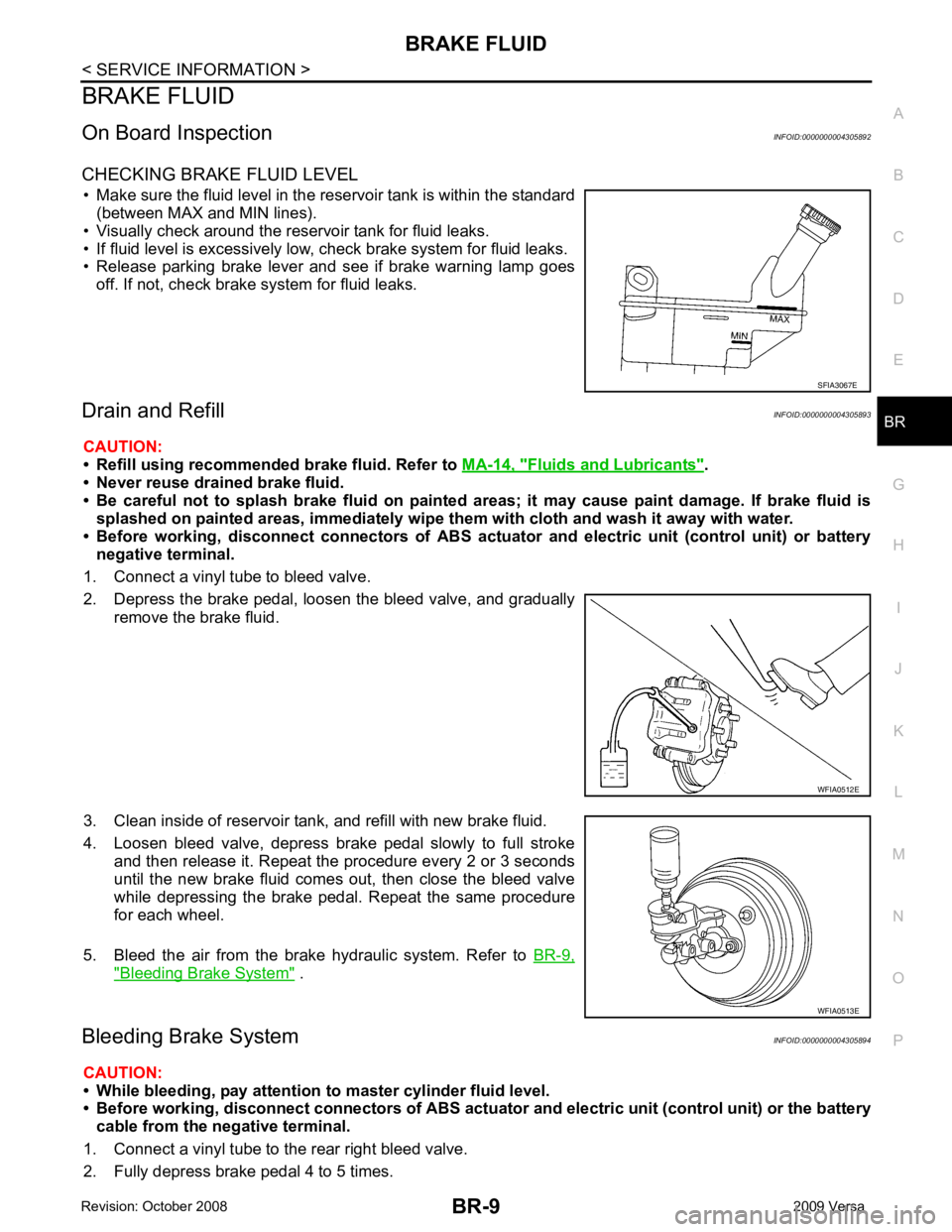
CHECKING BRAKE FLUID LEVEL • Make sure the fluid level in the reservoir tank is within the standard (between MAX and MIN lines).
• Visually check around the reservoir tank for fluid leaks.
• If fluid level is excessively low, check brake system for fluid leaks.
• Release parking brake lever and see if brake warning lamp goes
off. If not, check brake system for fluid leaks.
Drain and Refill INFOID:0000000004305893
CAUTION:
• Refill using recommended brake fluid. Refer to MA-14, " Fluids and Lubricants " .
• Never reuse drained brake fluid.
• Be careful not to splash brake fluid on painted areas; it may cause paint damage. If brake fluid is
splashed on painted areas, immediately wipe th em with cloth and wash it away with water.
• Before working, disconnect connect ors of ABS actuator and electric unit (control unit) or battery
negative terminal.
1. Connect a vinyl tube to bleed valve.
2. Depress the brake pedal, loosen the bleed valve, and gradually remove the brake fluid.
3. Clean inside of reservoir tank, and refill with new brake fluid.
4. Loosen bleed valve, depress brake pedal slowly to full stroke and then release it. Repeat the procedure every 2 or 3 seconds
until the new brake fluid comes out, then close the bleed valve
while depressing the brake pedal . Repeat the same procedure
for each wheel.
5. Bleed the air from the brake hydraulic system. Refer to BR-9," Bleeding Brake System " .
Bleeding Brake System INFOID:0000000004305894
CAUTION:
• While bleeding, pay attention to master cylinder fluid level.
• Before working, disconnect connectors of ABS actuator and electri c unit (control unit) or the battery
cable from the negative terminal.
1. Connect a vinyl tube to the rear right bleed valve.
2. Fully depress brake pedal 4 to 5 times.
Page 810 of 4331

Component " (front disc brake),
BR-33, " Compo-
nent " (rear drum brake).
6. Following the steps 1 to 5 above, with master cylinder reservoir tank filled at least half way, bleed air from
the rear right, front left, rear left, and front right brake, in that order.
Page 814 of 4331
" Hydraulic Circuit " .
Inspection INFOID:0000000004305900
CAUTION:
• Carefully monitor brake flui d level at master cylinder.
• Use the recommended new brake fluid. Refer to MA-14, " Fluids and Lubricants " .
• Be careful not to splash brake fluid on painted areas; it may cause paint damage. If brake fluid is
splashed on paint areas, wash it away with water immediately.
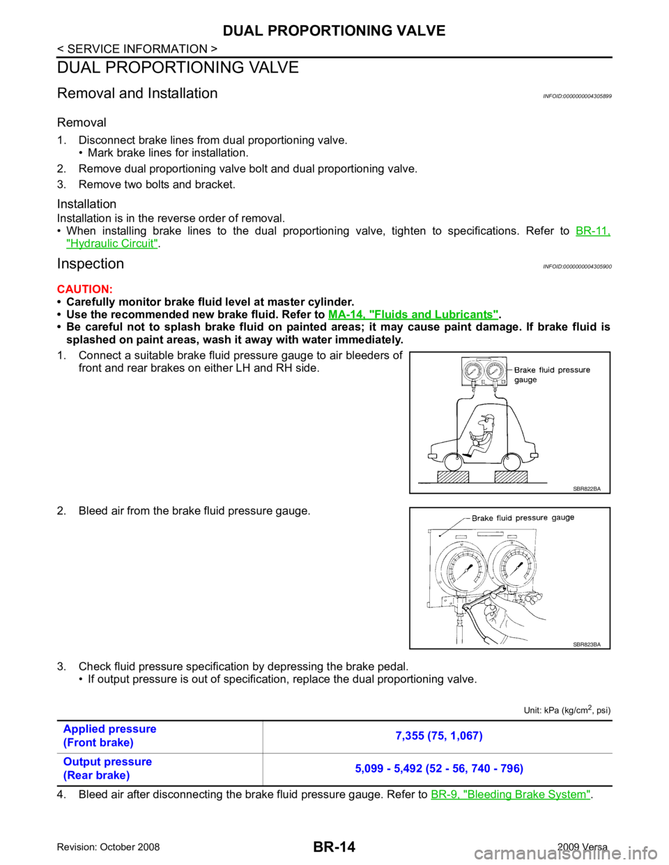
1. Connect a suitable brake fluid pressure gauge to air bleeders of front and rear brakes on either LH and RH side.
2. Bleed air from the brake fluid pressure gauge.
3. Check fluid pressure specific ation by depressing the brake pedal.
• If output pressure is out of specification, replace the dual proportioning valve.
Unit: kPa (kg/cm2
, psi)
4. Bleed air after disconnecting the brake fluid pressure gauge. Refer to BR-9, " Bleeding Brake System " .
Page 815 of 4331
BR
N
O P
BRAKE MASTER CYLINDER
On-Board Inspection INFOID:0000000004305901
LEAK INSPECTION • Check for leaks around the master cylinder installation surf ace, the reservoir tank installation surface, and all
the brake tube connections.
Removal and Installation INFOID:0000000004305902
CAUTION:
Be careful not to splash brake fluid on painted areas; it may cause paint damage. If brake fluid is
splashed on painted areas, immediately wipe th em with cloth and wash it away with water.
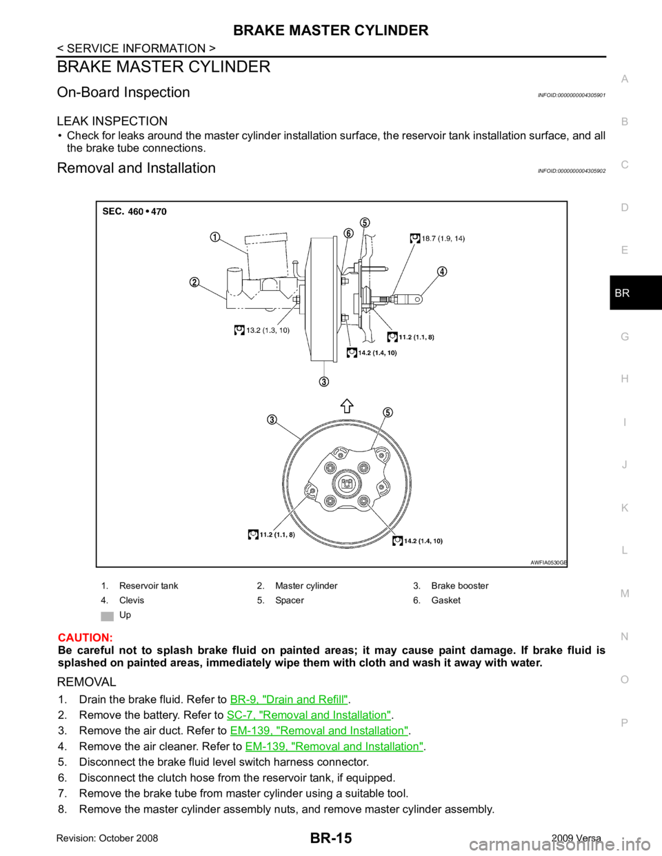
REMOVAL 1. Drain the brake fluid. Refer to BR-9, " Drain and Refill " .
2. Remove the battery. Refer to SC-7, " Removal and Installation " .
3. Remove the air duct. Refer to EM-139, " Removal and Installation " .
4. Remove the air cleaner. Refer to EM-139, " Removal and Installation " .
5. Disconnect the brake fluid level switch harness connector.
6. Disconnect the clutch hose from the reservoir tank, if equipped.
7. Remove the brake tube from master cylinder using a suitable tool.
8. Remove the master cylinder assembly nuts, and remove master cylinder assembly. 1. Reservoir tank 2. Master cylinder 3. Brake booster
4. Clevis 5. Spacer 6. Gasket
Up
Page 816 of 4331
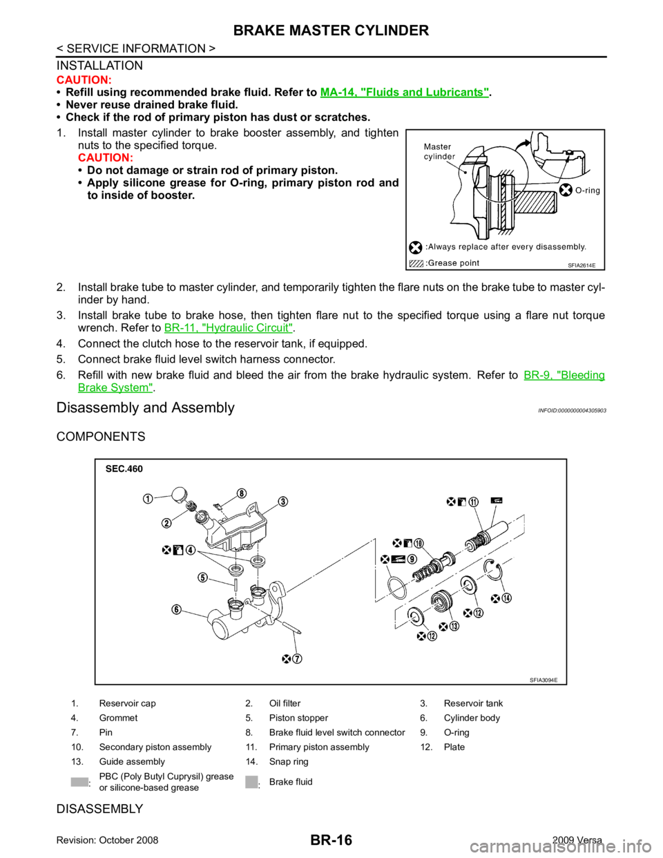
Fluids and Lubricants " .
• Never reuse drained brake fluid.
• Check if the rod of primary piston has dust or scratches.
1. Install master cylinder to brake booster assembly, and tighten nuts to the specified torque.
CAUTION:
• Do not damage or strain rod of primary piston.
• Apply silicone grease for O-ring, primary piston rod and to inside of booster.
2. Install brake tube to master cylinder, and temporarily tighten the flare nuts on the brake tube to master cyl-
inder by hand.
3. Install brake tube to brake hose, then tighten flare nut to the specified torque using a flare nut torque
wrench. Refer to BR-11, " Hydraulic Circuit " .
4. Connect the clutch hose to the reservoir tank, if equipped.
5. Connect brake fluid level switch harness connector.
6. Refill with new brake fluid and bleed the air from the brake hydraulic system. Refer toBR-9, " Bleeding
Brake System " .
Disassembly and Assembly INFOID:0000000004305903
COMPONENTS
DISASSEMBLY
Page 819 of 4331
BR
N
O P
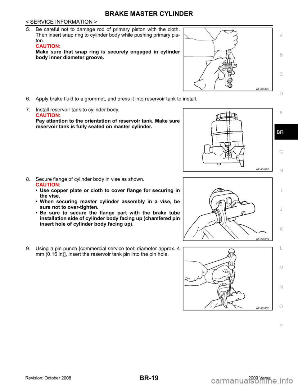
5. Be careful not to damage rod of primary piston with the cloth.
Then insert snap ring to cylinder body while pushing primary pis-
ton.
CAUTION:
Make sure that snap ring is securely engaged in cylinder
body inner diameter groove.
6. Apply brake fluid to a grommet, and press it into reservoir tank to install.
7. Install reservoir tank to cylinder body. CAUTION:
Pay attention to the orientatio n of reservoir tank. Make sure
reservoir tank is fully seated on master cylinder.
8. Secure flange of cylinder body in vise as shown. CAUTION:
• Use copper plate or cloth to cover flange for securing in
the vise.
• When securing master cylinder assembly in a vise, be sure not to over-tighten.
• Be sure to secure the flange part with the brake tube
installation side of cylinder body facing up (chamfered pin
insert hole of cylinder body facing up).
9. Using a pin punch [commercial service tool: diameter approx. 4 mm (0.16 in)], insert the reservoir tank pin into the pin hole. WFIA0515E
Page 821 of 4331
BRAKE BOOSTER
BR-21
< SERVICE INFORMATION >
C
D E
G H
I
J
K L
M A
B BR
N
O P
Removal and Installation
INFOID:0000000004305905
REMOVAL CAUTION:
• Be careful not to splash brake fluid on painte d areas such as body. It may cause paint damage. If
brake fluid is splashed on painte d surfaces of body, wipe them with cloth immediately and then wash
it away with water.
• Be careful not to deform or bend brake tub es while removing and installing brake booster.
• Replace clevis pin if it is damaged.
• Be careful not to damage brake booster stud bolt thr eads. If brake booster is tilted or inclined during
installation, dash panel may damage the threads.
1. Remove vacuum hose from brake booster.
2. Remove master cylinder assembly. Refer to BR-15, " Removal and Installation " .
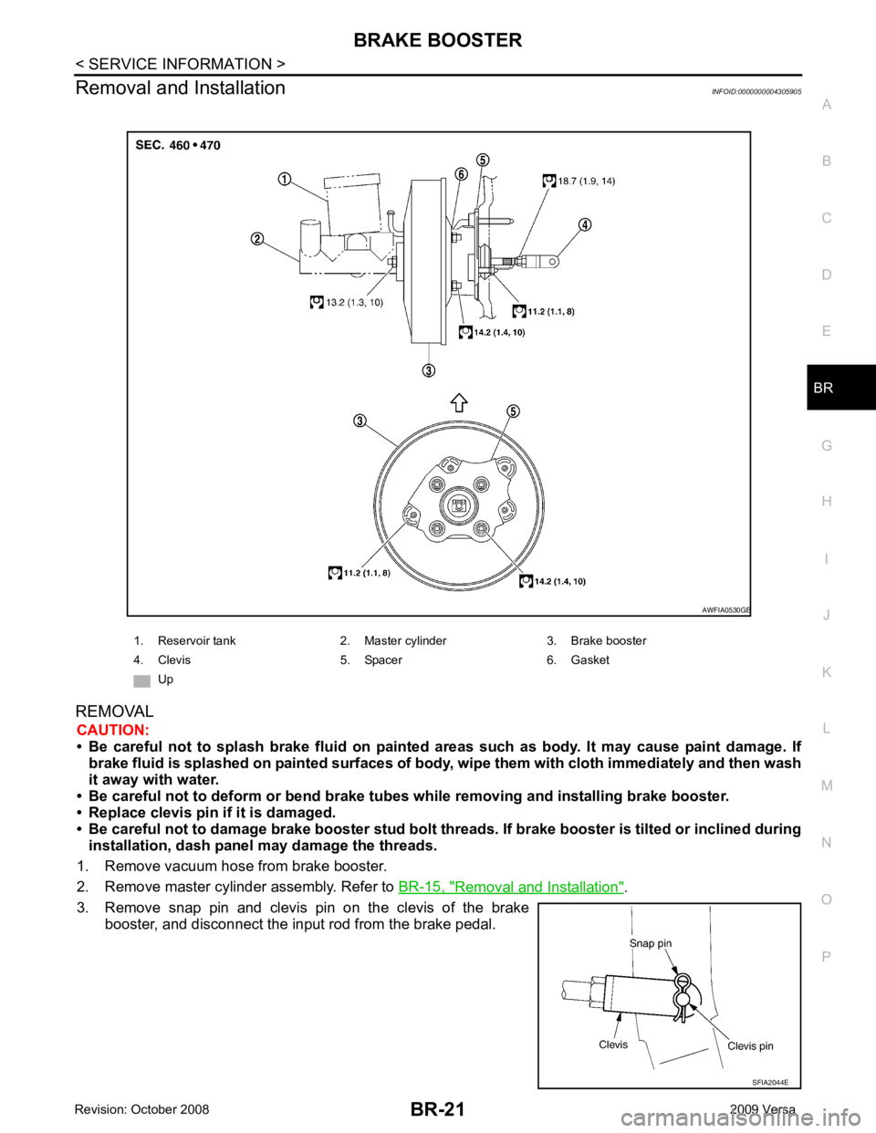
3. Remove snap pin and clevis pin on the clevis of the brake booster, and disconnect the input rod from the brake pedal. 1. Reservoir tank 2. Master cylinder 3. Brake booster
4. Clevis 5. Spacer 6. Gasket Up AWFIA0530GB
SFIA2044E
Page 838 of 4331

Front brake Brake model CLZ25VF
Cylinder bore diameter 57.2 mm (2.252 in)
Pad
Length × width × thickness 125.6 mm
× 48.0 mm × 9.5 mm
(4.945 in × 1.890 in × 0.374 in)
Rotor outer diameter × thickness 280 mm × 24.0 mm (11.02 in × 0.945 in)
Rear brake Brake model LT23 Cylinder bore diameter 19.06 mm (0.750 in)
Drum inner diameter 228.6 mm (9.000 in)
Master cylinder Cylinder bore diameter 23.81 ± 0.015 mm (0.937 ± 0.001 in)
Brake booster Booster model C255 Diaphragm diameter 255 mm (10.04 in)
Recommended brake fluid DOT 3