p2135 NISSAN TIIDA 2009 Service Repair Manual
[x] Cancel search | Manufacturer: NISSAN, Model Year: 2009, Model line: TIIDA, Model: NISSAN TIIDA 2009Pages: 4331, PDF Size: 58.04 MB
Page 1361 of 4331

EC
A
N
O P
Diagnosis Procedure ...........................................
..
349
P0507 ISC SYSTEM ....................................... ..351
Description .......................................................... ..351
DTC Logic ........................................................... ..351
Diagnosis Procedure ........................................... ..351
P0603 ECM POWER SUPPLY ....................... ..353
Description .......................................................... ..353
DTC Logic ........................................................... ..353
Diagnosis Procedure ........................................... ..353
P0605 ECM ..................................................... ..355
Description .......................................................... ..355
DTC Logic ........................................................... ..355
Diagnosis Procedure ........................................... ..356
P0607 ECM ..................................................... ..357
Description .......................................................... ..357
DTC Logic ........................................................... ..357
Diagnosis Procedure ........................................... ..357
P0643 SENSOR POWER SUPPLY ............... ..358
DTC Logic ........................................................... ..358
Wiring Diagram ................................................... ..359
Diagnosis Procedure ........................................... ..359
P0850 PNP SWITCH ...................................... ..362
Description .......................................................... ..362
DTC Logic ........................................................... ..362
Component Function Check ................................ ..363
Wiring Diagram ................................................... ..364
Diagnosis Procedure ........................................... ..364
P1148 CLOSED LOOP CONTROL ................ ..367
DTC Logic ........................................................... ..367
P1217 ENGINE OVER TEMPERATURE ....... ..368
DTC Logic ........................................................... ..368
Component Function Check ................................ ..368
Diagnosis Procedure ........................................... ..369
P1225 TP SENSOR ........................................ ..372
Description .......................................................... ..372
DTC Logic ........................................................... ..372
Diagnosis Procedure ........................................... ..372
Special Repair Requirem ent .................................373
P1226 TP SENSOR ........................................ ..374
Description .......................................................... ..374
DTC Logic ........................................................... ..374
Diagnosis Procedure ........................................... ..374
Special Repair Requirem ent .................................375
P1421 COLD START CONTROL ................... ..376
Description .......................................................... ..376
DTC Logic ........................................................... ..376
Diagnosis Procedure ........................................... ..376
P1715 INPUT SPEED SENSOR (PRIMARY
SPEED SENSOR) .......................................... ..
378
Description .......................................................... ..378 DTC Logic ............................................................
..378
Diagnosis Procedure ........................................... ..378
P1805 BRAKE SWITCH ................................. 380
Description ........................................................... ..380
DTC Logic ............................................................ ..380
Wiring Diagram .................................................... ..381
Diagnosis Procedure ........................................... ..381
Component Inspection (Stop Lamp Switch) ........ ..383
P2100, P2103 THROTTLE CONTROL MO-
TOR RELAY .................................................... 384
Description ........................................................... ..384
DTC Logic ............................................................ ..384
Wiring Diagram .................................................... ..385
Diagnosis Procedure ........................................... ..385
P2101 ELECTRIC THROTTLE CONTROL
FUNCTION ....... ............................................... 388
Description ........................................................... ..388
DTC Logic ............................................................ ..388
Wiring Diagram .................................................... ..389
Diagnosis Procedure ........................................... ..389
Component Inspection ......................................... ..392
Special Repair Requiremen t ..................................392
P2118 THROTTLE CONTROL MOTOR ......... 393
Description ........................................................... ..393
DTC Logic ............................................................ ..393
Wiring Diagram .................................................... ..394
Diagnosis Procedure ........................................... ..394
Component Inspection ......................................... ..395
Special Repair Requiremen t ..................................396
P2119 ELECTRIC THROTTLE CONTROL
ACTUATOR ..................................................... 397
Description ........................................................... ..397
DTC Logic ............................................................ ..397
Diagnosis Procedure ........................................... ..397
Special Repair Requiremen t ..................................398
P2122, P2123 APP SENSOR ......................... 399
Description ........................................................... ..399
DTC Logic ............................................................ ..399
Wiring Diagram .................................................... ..400
Diagnosis Procedure ........................................... ..400
Component Inspection ......................................... ..402
Special Repair Requiremen t ..................................402
P2127, P2128 APP SENSOR ......................... 403
Description ........................................................... ..403
DTC Logic ............................................................ ..403
Wiring Diagram .................................................... ..404
Diagnosis Procedure ........................................... ..404
Component Inspection ......................................... ..406
Special Repair Requiremen t ..................................407
P2135 TP SENSOR ......................................... 408
Description ........................................................... ..408
DTC Logic ............................................................ ..408
Page 1369 of 4331

EC
A
N
O P
DTC Confirmation Procedure ..............................
..
940
Diagnosis Procedure ........................................... ..941
DTC P2122, P2123 APP SENSOR ................ ..942
Component Description ....................................... ..942
CONSULT-III Refe rence Value in Data Monitor
Mode ................................................................... ..
942
On Board Diagnosis Logic .................................. ..942
DTC Confirmation Procedure .............................. ..942
Wiring Diagram ................................................... ..943
Diagnosis Procedure ........................................... ..944
Component Inspection ........................................ ..946
Removal and Installation .......................................946
DTC P2127, P2128 APP SENSOR ................ ..947
Component Description ....................................... ..947
CONSULT-III Refe rence Value in Data Monitor
Mode ................................................................... ..
947
On Board Diagnosis Logic .................................. ..947
DTC Confirmation Procedure .............................. ..948
Wiring Diagram ................................................... ..949
Diagnosis Procedure ........................................... ..950
Component Inspection ........................................ ..952
Removal and Installation .......................................953
DTC P2135 TP SENSOR ............................... ..954
Component Description ....................................... ..954
CONSULT-III Refe rence Value in Data Monitor
Mode ................................................................... ..
954
On Board Diagnosis Logic .................................. ..954
DTC Confirmation Procedure .............................. ..954
Wiring Diagram ................................................... ..955
Diagnosis Procedure ........................................... ..956
Component Inspection ........................................ ..958
Removal and Installation .......................................958
DTC P2138 APP SENSOR ............................. ..959
Component Description ....................................... ..959
CONSULT-III Refe rence Value in Data Monitor
Mode ................................................................... ..
959
On Board Diagnosis Logic .................................. ..959
DTC Confirmation Procedure .............................. ..960
Wiring Diagram ................................................... ..961
Diagnosis Procedure ........................................... ..962
Component Inspection ........................................ ..965
Removal and Installation .......................................965
DTC P2A00 A/F SENSOR 1 ........................... ..966
Component Description ....................................... ..966
CONSULT-III Refe rence Value in Data Monitor
Mode ................................................................... ..
966
On Board Diagnosis Logic .................................. ..966
DTC Confirmation Procedure .............................. ..966
Wiring Diagram ................................................... ..968
Diagnosis Procedure ........................................... ..969
Removal and Installation .......................................972
ASCD BRAKE SWITCH ................................. ..973
Component Description ....................................... ..973 CONSULT-III Reference Va
lue in Data Monitor
Mode .................................................................... ..
973
Wiring Diagram .................................................... ..974
Diagnosis Procedure ........................................... ..975
Component Inspection ......................................... ..979
ASCD INDICATOR .......................................... 981
Component Description ....................................... ..981
CONSULT-III Reference Va lue in Data Monitor
Mode .................................................................... ..
981
Wiring Diagram .................................................... ..982
Diagnosis Procedure ........................................... ..982
ELECTRICAL LOAD SIGNAL ........................ 984
CONSULT-III Reference Va lue in Data Monitor
Mode .................................................................... ..
984
Diagnosis Procedure ........................................... ..984
FUEL INJECTOR ............................................ 986
Component Description ....................................... ..986
CONSULT-III Reference Va lue in Data Monitor
Mode .................................................................... ..
986
Wiring Diagram .................................................... ..987
Diagnosis Procedure ........................................... ..988
Component Inspection ......................................... ..990
Removal and Installation ..................................... ..990
FUEL PUMP .................................................... 991
Description ........................................................... ..991
CONSULT-III Reference Va lue in Data Monitor
Mode .................................................................... ..
991
Wiring Diagram .................................................... ..992
Diagnosis Procedure ........................................... ..993
Component Inspection ......................................... ..995
Removal and Installation ..................................... ..995
IGNITION SIGNAL .......................................... 996
Component Description ....................................... ..996
Wiring Diagram .................................................... ..997
Diagnosis Procedure ........................................... 1000
Component Inspection ......................................... 1003
Removal and Installation ..................................... 1004
REFRIGERANT PRESSURE SENSOR ......... 1005
Component Description ....................................... 1005
Wiring Diagram .................................................... 1006
Diagnosis Procedure ........................................... 1007
Removal and Installation ..................................... 1009
MIL AND DATA LINK CONNECTOR ............ 1010
Wiring Diagram .................................................... 1010
SERVICE DATA AND SPECIFICATIONS
(SDS) .............................................................. 1012
Fuel Pressure ...................................................... 1012
Idle Speed and Ignition Timing ............................ 1012
Calculated Load Value ........................................ 1012
Mass Air Flow Sensor .......................................... 1012
Intake Air Temperature Sensor ........................... 1012
Engine Coolant Temperature Sensor .................. 1012
Air Fuel Ratio (A/F) Sensor 1 Heater ................... 1013
Page 1764 of 4331
![NISSAN TIIDA 2009 Service Repair Manual EC-408< COMPONENT DIAGNOSIS >
[HR16DE]
P2135 TP SENSOR
P2135 TP SENSOR
Description INFOID:0000000004780448
Electric throttle control actuator consists of throttle control motor,
throttle posit](/img/5/57398/w960_57398-1763.png "NISSAN TIIDA 2009 Service Repair Manual EC-408< COMPONENT DIAGNOSIS >
[HR16DE]
P2135 TP SENSOR
P2135 TP SENSOR
Description INFOID:0000000004780448
Electric throttle control actuator consists of throttle control motor,
throttle posit")
EC-408< COMPONENT DIAGNOSIS >
[HR16DE]
P2135 TP SENSOR
P2135 TP SENSOR
Description INFOID:0000000004780448
Electric throttle control actuator consists of throttle control motor,
throttle position sensor, etc. The throttle position sensor responds to
the throttle valve movement.
The throttle position sensor has two sensors. These sensors are a
kind of potentiometer which transform the throttle valve position into
output voltage, and emit the voltage signals to the ECM. The ECM
judges the current opening angle of the throttle valve from these sig-
nals and controls the throttle valve opening angle in response to
driving conditions via the throttle control motor.
DTC Logic INFOID:0000000004780329
DTC DETECTION LOGIC
NOTE:
If DTC P2135 is displayed with DTC P0643, first pe rform the trouble diagnosis for DTC P0643. Refer to
EC-358, " DTC Logic " .
DTC CONFIRMATION PROCEDURE 1.
PRECONDITIONING
If DTC Confirmation Procedure has been previously conduc ted, always turn ignition switch OFF and wait at
least 10 seconds before conducting the next test.
TESTING CONDITION:
Before performing the following procedure, confirm that battery voltage is more than 8 V at idle.
>> GO TO 2. 2.
PERFORM DTC CONFIRMATION PROCEDURE
1. Start engine and let it idle for 1 second.
2. Check DTC.
Is DTC detected? YES >> Go to
EC-409, " Diagnosis Procedure " .
NO >> INSPECTION END PBIB0145E
DTC No. Trouble diagnosis name DTC detecting condition Possible cause
P2135 Throttle position sensor
circuit range/perfor-
mance Rationally incorrect voltage is sent to ECM
compared with the signals from TP sensor 1
and TP sensor 2. • Harness or connector
(TP sensor 1 or 2 circuit is open or shorted.)
• Electric throttle control actuator (TP sensor 1 or 2)
Page 1766 of 4331
![NISSAN TIIDA 2009 Service Repair Manual EC-410< COMPONENT DIAGNOSIS >
[HR16DE]
P2135 TP SENSOR
YES >> GO TO 2.
NO >> Repair or replace ground connection. 2.
CHECK THROTTLE POSITION SE NSOR POWER SUPPLY CIRCUIT
1. Disconnect electric throttl](/img/5/57398/w960_57398-1765.png "NISSAN TIIDA 2009 Service Repair Manual EC-410< COMPONENT DIAGNOSIS >
[HR16DE]
P2135 TP SENSOR
YES >> GO TO 2.
NO >> Repair or replace ground connection. 2.
CHECK THROTTLE POSITION SE NSOR POWER SUPPLY CIRCUIT
1. Disconnect electric throttl")
EC-410< COMPONENT DIAGNOSIS >
[HR16DE]
P2135 TP SENSOR
YES >> GO TO 2.
NO >> Repair or replace ground connection. 2.
CHECK THROTTLE POSITION SE NSOR POWER SUPPLY CIRCUIT
1. Disconnect electric throttle control actuator harness connector.
2. Turn ignition switch ON.
3. Check the voltage between electric throttle control actuator har-
ness connector and ground.
Is the inspection result normal? YES >> GO TO 3.
NO >> Repair open circuit or short to ground or short to power
in harness or connectors. 3.
CHECK THROTTLE POSITION SENSOR GROUND CIRCUIT FOR OPEN AND SHORT
1. Turn ignition switch OFF.
2. Disconnect ECM harness connector.
3. Check the continuity between electric thro ttle control actuator harness connector and ground.
4. Also check harness for short to ground and short to power.
Is the inspection result normal? YES >> GO TO 4.
NO >> Repair open circuit or short to ground or short to power in harness or connectors. 4.
CHECK THROTTLE POSITION SENSOR INPUT SIGNAL CIRCUIT FOR OPEN AND SHORT
1. Check the continuity between electric thro ttle control actuator harness connector and ground.
2. Also check harness for short to ground and short to power.
Is the inspection result normal? YES >> GO TO 5.
NO >> Repair open circuit or short to ground or short to power in harness or connectors. 5.
CHECK THROTTLE POSITION SENSOR
Refer to EC-411, " Component Inspection " .
Is the inspection result normal? YES >> GO TO 7.
NO >> GO TO 6. 6.
REPLACE ELECTRIC THROTTLE CONTROL ACTUATOR
1. Replace electric throttle control actuator.
2. Perform EC-411, " Special Repair Requirement " .
>> INSPECTION END
Electric throttle control actuator
Ground Voltage
Connector Terminal
F7 2 Ground Approx. 5 V PBIB3311E
Electric throttle control actuator ECM
Continuity
Connector Terminal Connector Terminal
F7 4 F11 36 Existed Electric throttle control actuator ECM
Continuity
Connector Terminal Connector Terminal
F7 1
F1133
Existed
3 34
Page 1767 of 4331
![NISSAN TIIDA 2009 Service Repair Manual P2135 TP SENSOR
EC-411
< COMPONENT DIAGNOSIS >
[HR16DE] C
D E
F
G H
I
J
K L
M A EC
NP
O 7.
CHECK INTERMITTENT INCIDENT
Refer to EC-120, " Diagnosis Procedure " .
>> INSPECTION END
Component Inspectio](/img/5/57398/w960_57398-1766.png "NISSAN TIIDA 2009 Service Repair Manual P2135 TP SENSOR
EC-411
< COMPONENT DIAGNOSIS >
[HR16DE] C
D E
F
G H
I
J
K L
M A EC
NP
O 7.
CHECK INTERMITTENT INCIDENT
Refer to EC-120, \" Diagnosis Procedure \" .
>> INSPECTION END
Component Inspectio")
P2135 TP SENSOR
EC-411
< COMPONENT DIAGNOSIS >
[HR16DE] C
D E
F
G H
I
J
K L
M A EC
NP
O 7.
CHECK INTERMITTENT INCIDENT
Refer to EC-120, " Diagnosis Procedure " .
>> INSPECTION END
Component Inspection INFOID:00000000047804491.
CHECK THROTTLE POSITION SENSOR
1. Turn ignition switch OFF.
2. Reconnect all harness connectors disconnected.
3. Perform EC-411, " Special Repair Requirement " .
4. Turn ignition switch ON.
5. Set selector lever to D (A/T) or 1st (M/T) position.
6. Check the voltage between ECM harness connector and
ground.
Is the inspection result normal? YES >> INSPECTION END
NO >> GO TO 2. 2.
REPLACE ELECTRIC THROTTLE CONTROL ACTUATOR
1. Replace electric throttle control actuator.
2. Perform EC-411, " Special Repair Requirement " .
>> INSPECTION END
Special Repair Requirement INFOID:00000000047804501.
PERFORM THROTTLE VALVE CL OSED POSITION LEARNING
Refer to EC-31, " THROTTLE VALVE CLOSED POSITION L
EARNING : Special Repair Requirement "
>> GO TO 2.
2.
PERFORM IDLE AIR VOLUME LEARNING
Refer to EC-32, " IDLE AIR VOLUME LEARNING : Special Repair Requirement "
>> ENDECM
Ground Condition Voltage
Connector Terminal
F11 33
(TP sensor
1 signal)
GroundAccelerator
pedal Fully released
More than
0.36V
Fully de-
pressed Less than
4.75V
34
(TP sensor 2 signal) Fully released
Less than
4.75V
Fully de-
pressed More than
0.36V PBIB3038E
Page 1829 of 4331

EC
NP
O
DTC RELATED ITEM
Detected items
Engine operating condition in
fail-safe mode Remarks
Malfunction indicator
lamp circuit Engine speed will not rise
more than 2,500 rpm due to
the fuel cut When there is an open circuit on MIL circuit, the ECM cannot warn the driver by
lighting up MIL when there is malfunction on engine control system.
Therefore, when electrical controlled throttle and part of ECM related diagnoses
are continuously detected as NG for 5 trips, ECM warns the driver that engine
control system malfunctions and MIL circuit is open by means of operating fail-
safe function.
The fail-safe function also operates when above diagnoses except MIL circuit
are detected and demands the driver to repair the malfunction. DTC No. Detected items Engine operating condition in fail-safe mode
P0011 Intake valve timing control The signal is not energized to the intake valve timing control solenoid valve and the valve control does not function.
P0102
P0103 Mass air flow sensor circuit Engine speed will not rise more than 2,400 rpm due to the fuel cut.
P0117
P0118 Engine coolant tempera-
ture sensor circuit Engine coolant temperature will be determined by ECM based on the following condition.
CONSULT-III displays the engine coolant temperature decided by ECM.
Condition Engine coolant temperature decided
(CONSULT-III display)
Just as ignition switch is turned ON
or START 40
°C (104 °F)
More than approx. 4 minutes after
engine starting 80
°C (176 °F)
Except as shown above 40 - 80
°C (104 - 176 °F)
(Depends on the time)
When the fail-safe system for engine coolant temperature sensor is activated, the cooling
fan operates while engine is running.
P0122
P0123
P0222
P0223
P2135 Throttle position sensor The ECM controls the electric throttle control actuator in regulating the throttle opening in
order for the idle position to be within +10 degrees.
The ECM regulates the opening speed of the throttle valve to be slower than the normal
condition.
So, the acceleration will be poor.
P0643 Sensor power supply ECM stops the electric throttle control actuator control, throttle valve is maintained at a fixed opening (approx. 5 degrees) by the return spring.
P0605 ECM (When ECM calculation function is malfunctioning:) ECM stops the electric throttle control actuator control, throttle valve is maintained at a
fixed opening (approx. 5 degrees) by the return spring.
P1805 Brake switch ECM controls the electric throttle control actuator by regulating the throttle opening to a small range.
Therefore, acceleration will be poor.
Vehicle condition Driving condition
When engine is idling Normal
When accelerating Poor acceleration
P2100
P2103 Throttle control motor relay ECM stops the electric throttle control actuator control, throttle valve is maintained at a
fixed opening (approx. 5 degrees) by the return spring.
P2101 Electric th rottle control
function ECM stops the electric throttle control actuator control, throttle valve is maintained at a
fixed opening (approx. 5 degrees) by the return spring.
P2118 Throttle control motor ECM stops the electric throttle control actuator control, throttle valve is maintained at a fixed opening (approx. 5 degrees) by the return spring.
Page 1830 of 4331

Priority Detected items (DTC)
1 • U0101 U0140 U1001 CAN communication line • P0101 P0102 P0103 Mass air flow sensor
• P0112 P0113 P0127 Intake air temperature sensor
• P0116 P0117 P0118 P0125 Engine coolant temperature sensor
• P0122 P0123 P0222 P0223 P1225 P1226 P2135 Throttle position sensor
• P0128 Thermostat function
• P0181 P0182 P0183 Fuel tank temperature sensor
• P0327 P0328 Knock sensor
• P0335 Crankshaft position sensor (POS)
• P0340 Camshaft posi tion sensor (PHASE)
• P0460 P0461 P0462 P0463 Fuel level sensor
• P0500 Vehicle speed sensor
• P0605 P0607 ECM
• P0643 Sensor power supply
• P0705 P0850 Park/neutral position (PNP) switch
• P1610 - P1615 NATS
• P2122 P2123 P2127 P2128 P2138 Accelerator pedal position sensor
Page 1834 of 4331
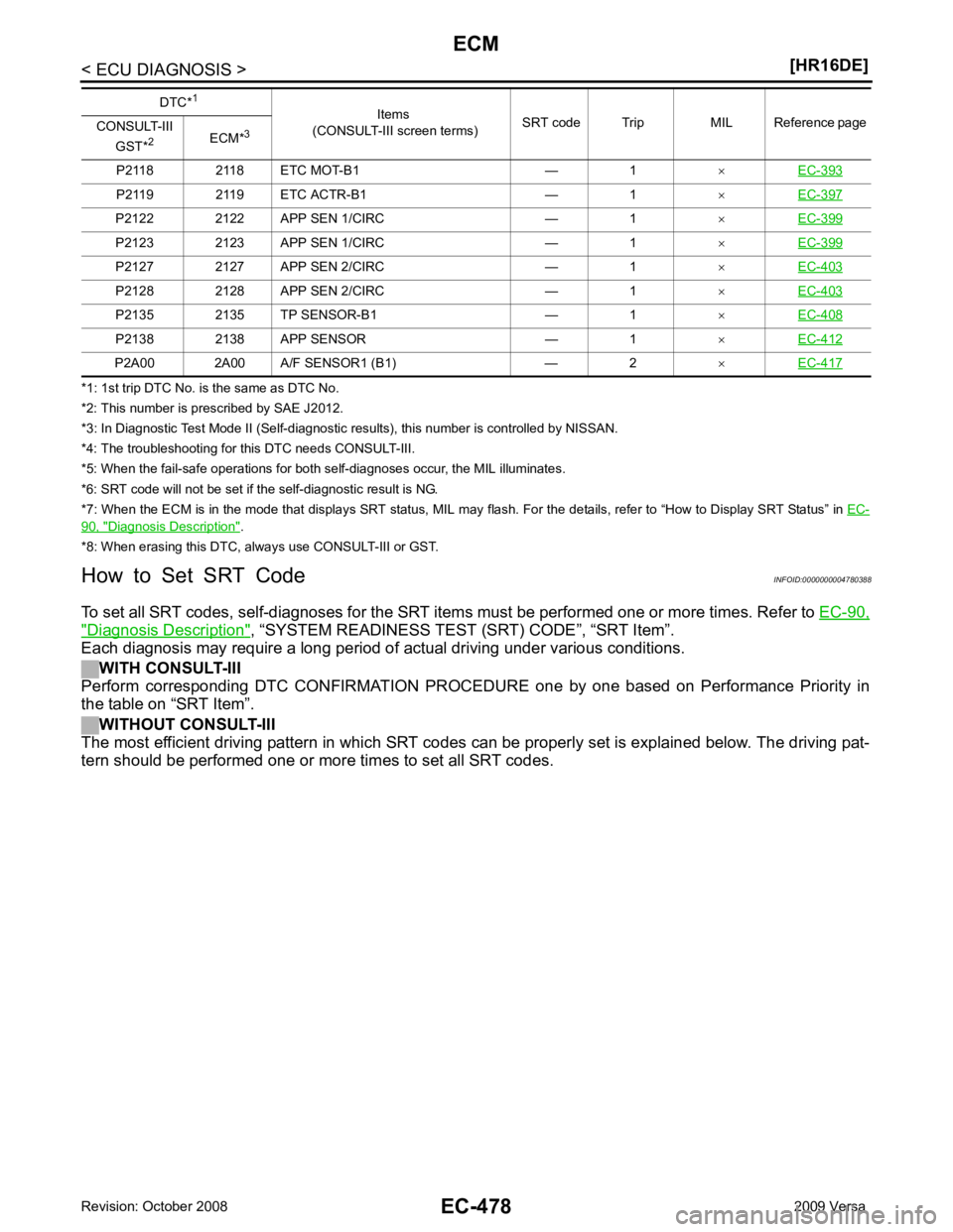
90, " Diagnosis Description " .
*8: When erasing this DTC, al ways use CONSULT-III or GST.
How to Set SRT Code INFOID:0000000004780388
To set all SRT codes, self-diagnoses for the SRT items must be performed one or more times. Refer to EC-90," Diagnosis Description " , “SYSTEM READINESS TEST (SRT) CODE”, “SRT Item”.
Each diagnosis may require a long period of actual driving under various conditions.
WITH CONSULT-III
Perform corresponding DTC CONFIRMATION PROCE DURE one by one based on Performance Priority in
the table on “SRT Item”.
WITHOUT CONSULT-III
The most efficient driving pattern in which SRT codes can be properly set is explained below. The driving pat-
tern should be performed one or more times to set all SRT codes. P2118 2118 ETC MOT-B1 — 1
×EC-393 P2119 2119 ETC ACTR-B1 — 1
×EC-397 P2122 2122 APP SEN 1/CIRC — 1
×EC-399 P2123 2123 APP SEN 1/CIRC — 1
×EC-399 P2127 2127 APP SEN 2/CIRC — 1
×EC-403 P2128 2128 APP SEN 2/CIRC — 1
×EC-403 P2135 2135 TP SENSOR-B1 — 1
×EC-408 P2138 2138 APP SENSOR — 1
×EC-412 P2A00 2A00 A/F SENSOR1 (B1) — 2
×EC-417 DTC*
1
Items
(CONSULT-III screen terms) SRT code Trip MIL Reference page
CONSULT-III
GST* 2
ECM*3
Page 1867 of 4331
EC
NP
O
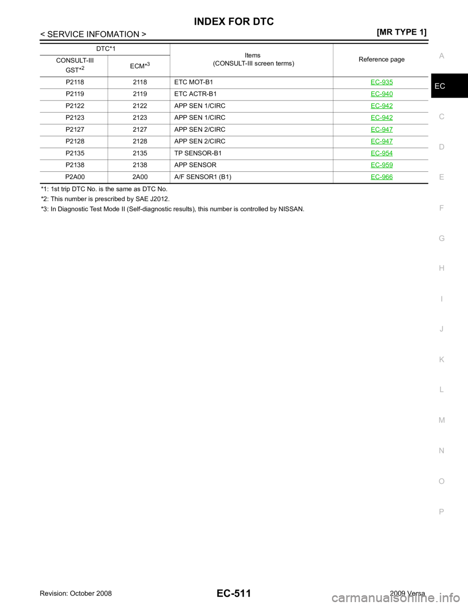
*1: 1st trip DTC No. is
the same as DTC No.
*2: This number is prescribed by SAE J2012.
*3: In Diagnostic Test Mode II (Self-diagnostic results), this number is controlled by NISSAN.
P2118 2118 ETC MOT-B1
EC-935P2119 2119 ETC ACTR-B1
EC-940P2122 2122 APP SEN 1/CIRC
EC-942P2123 2123 APP SEN 1/CIRC
EC-942P2127 2127 APP SEN 2/CIRC
EC-947P2128 2128 APP SEN 2/CIRC
EC-947P2135 2135 TP SENSOR-B1
EC-954P2138 2138 APP SENSOR
EC-959P2A00 2A00 A/F SENSOR1 (B1)
EC-966DTC*1
Items
(CONSULT-III screen terms) Reference page
CONSULT-III
GST* 2
ECM*3
Page 1901 of 4331
EC
NP
O
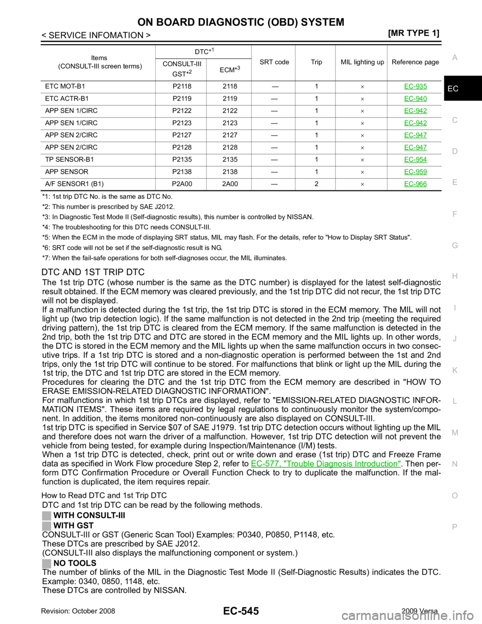
*1: 1st trip DTC No. is
the same as DTC No.
*2: This number is prescribed by SAE J2012.
*3: In Diagnostic Test Mode II (Self-diagnostic results), this number is controlled by NISSAN.
*4: The troubleshooting for this DTC needs CONSULT-III.
*5: When the ECM in the mode of displaying SRT status, MIL may flash. For the details, refer to "How to Display SRT Status".
*6: SRT code will not be set if the self-diagnostic result is NG.
*7: When the fail-safe operations for both self-diagnoses occur, the MIL illuminates.
DTC AND 1ST TRIP DTC The 1st trip DTC (whose number is the same as the DT C number) is displayed for the latest self-diagnostic
result obtained. If the ECM memory was cleared previously , and the 1st trip DTC did not recur, the 1st trip DTC
will not be displayed.
If a malfunction is detected during the 1st trip, the 1st trip DTC is stored in the ECM memory. The MIL will not
light up (two trip detection logic). If the same malfunc tion is not detected in the 2nd trip (meeting the required
driving pattern), the 1st trip DTC is cleared from the ECM memory. If the same malfunction is detected in the
2nd trip, both the 1st trip DTC and DTC are stored in t he ECM memory and the MIL lights up. In other words,
the DTC is stored in the ECM memory and the MIL light s up when the same malfunction occurs in two consec-
utive trips. If a 1st trip DTC is stored and a non-diagnostic operation is performed between the 1st and 2nd
trips, only the 1st trip DTC will continue to be stored. Fo r malfunctions that blink or light up the MIL during the
1st trip, the DTC and 1st trip DTC are stored in the ECM memory.
Procedures for clearing the DTC and the 1st trip DT C from the ECM memory are described in "HOW TO
ERASE EMISSION-RELATED DIAGNOSTIC INFORMATION".
For malfunctions in which 1st trip DTCs are displa yed, refer to "EMISSION-RELATED DIAGNOSTIC INFOR-
MATION ITEMS". These items are required by legal r egulations to continuously monitor the system/compo-
nent. In addition, the items monitored non-cont inuously are also displayed on CONSULT-III.
1st trip DTC is specified in Service $07 of SAE J1979. 1st trip DTC detection occurs without lighting up the MIL
and therefore does not warn the driver of a malfunction. However, 1st trip DTC detection will not prevent the
vehicle from being tested, for example during Inspection/Maintenance (I/M) tests.
When a 1st trip DTC is detected, check, print out or write down and erase (1st trip) DTC and Freeze Frame
data as specified in Work Flow procedure Step 2, refer to EC-577, " Trouble Diagnosis Introduction " . Then per-
form DTC Confirmation Procedure or Overall Function Che ck to try to duplicate the malfunction. If the mal-
function is duplicated, the item requires repair.
How to Read DTC and 1st Trip DTC DTC and 1st trip DTC can be read by the following methods.
WITH CONSULT-III
WITH GST
CONSULT-III or GST (Generic Scan Tool ) Examples: P0340, P0850, P1148, etc.
These DTCs are prescribed by SAE J2012.
(CONSULT-III also displays the malfunctioning component or system.)
NO TOOLS
The number of blinks of the MIL in the Diagnostic Test Mode II (Self-Diagnostic Results) indicates the DTC.
Example: 0340, 0850, 1148, etc.
These DTCs are controlled by NISSAN. ETC MOT-B1 P2118 2118 — 1
×EC-935 ETC ACTR-B1 P2119 2119 — 1
×EC-940 APP SEN 1/CIRC P2122 2122 — 1
×EC-942 APP SEN 1/CIRC P2123 2123 — 1
×EC-942 APP SEN 2/CIRC P2127 2127 — 1
×EC-947 APP SEN 2/CIRC P2128 2128 — 1
×EC-947 TP SENSOR-B1 P2135 2135 — 1
×EC-954 APP SENSOR P2138 2138 — 1
×EC-959 A/F SENSOR1 (B1) P2A00 2A00 — 2
×EC-966 Items
(CONSULT-III screen terms) DTC*
1
SRT code Trip MIL lighting up Reference page
CONSULT-III
GST* 2
ECM*3