ESP NISSAN TIIDA 2010 Service Repair Manual
[x] Cancel search | Manufacturer: NISSAN, Model Year: 2010, Model line: TIIDA, Model: NISSAN TIIDA 2010Pages: 3745, PDF Size: 73.67 MB
Page 2382 of 3745
COMPRESSION PRESSUREEM-23
< ON-VEHICLE MAINTENANCE > [HR16DE]
C
D
E
F
G H
I
J
K L
M A
EM
NP
O
COMPRESSION PRESSURE
InspectionINFOID:0000000005398044
1. Warm up engine thoroughly. Then, stop it.
2. Release fuel pressure. Refer to
EC-496, "
Inspection".
3. Remove ignition coil and spark plug from each cylinder. Refer to EM-46, "
Exploded View".
4. Connect an engine tachometer (not required in use of CONSULT-III).
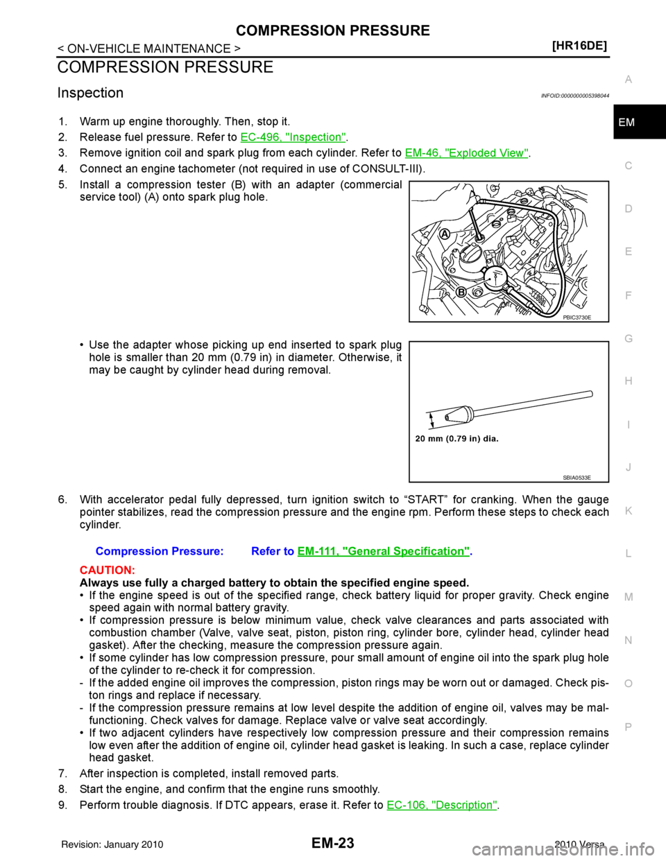
5. Install a compression tester (B) with an adapter (commercial service tool) (A) onto spark plug hole.
• Use the adapter whose picking up end inserted to spark plughole is smaller than 20 mm (0.79 in) in diameter. Otherwise, it
may be caught by cylinder head during removal.
6. With accelerator pedal fully depressed, turn ignition switch to “START” for cranking. When the gauge pointer stabilizes, read the compression pressure and the engine rpm. Perform these steps to check each
cylinder.
CAUTION:
Always use fully a charged battery to obtain the specified engine speed.
• If the engine speed is out of the specified range, check battery liquid for proper gravity. Check engine speed again with normal battery gravity.
• If compression pressure is below minimum value, check valve clearances and parts associated with combustion chamber (Valve, valve seat, piston, pi ston ring, cylinder bore, cylinder head, cylinder head
gasket). After the checking, measure the compression pressure again.
• If some cylinder has low compression pressure, pour small amount of engine oil into the spark plug hole
of the cylinder to re-check it for compression.
- If the added engine oil improves the compression, piston rings may be worn out or damaged. Check pis-
ton rings and replace if necessary.
- If the compression pressure remains at low level despite the addition of engine oil, valves may be mal- functioning. Check valves for damage. Replace valve or valve seat accordingly.
• If two adjacent cylinders have respectively low compression pressure and their compression remains low even after the addition of engine oil, cylinder head gasket is leaking. In such a case, replace cylinder
head gasket.
7. After inspection is completed, install removed parts.
8. Start the engine, and confirm that the engine runs smoothly.
9. Perform trouble diagnosis. If DTC appears, erase it. Refer to EC-106, "
Description".
PBIC3730E
SBIA0533E
Compression Pressure: Refer to E M - 111 , "General Specification".
Revision: January 20102010 Versa
Page 2394 of 3745
FUEL INJECTOR AND FUEL TUBEEM-35
< ON-VEHICLE REPAIR > [HR16DE]
C
D
E
F
G H
I
J
K L
M A
EM
NP
O
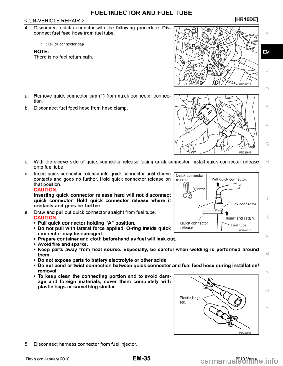
4. Disconnect quick connector with the following procedure. Dis-
connect fuel feed hose from fuel tube.
NOTE:
There is no fuel return path.
a. Remove quick connector cap (1) from quick connector connec- tion.
b. Disconnect fuel feed hose from hose clamp.
c. With the sleeve side of quick connector release facing quick connector, install quick connector release onto fuel tube.
d. Insert quick connector release into quick connector until sleeve contacts and goes no further. Hold quick connector release on
that position.
CAUTION:
Inserting quick connector re lease hard will not disconnect
quick connector. Hold qui ck connector release where it
contacts and goes no further.
e. Draw and pull out quick connector straight from fuel tube. CAUTION:
• Pull quick connector holding “A” position.
• Do not pull with lateral force applied. O-ring inside quickconnector may be damaged.
• Prepare container and cloth be forehand as fuel will leak out.
• Avoid fire and sparks.
• Keep parts away from heat source. Especially, be careful when welding is performed around
them.
• Do not expose parts to battery electrolyte or other acids.
• Do not bend or twist connection between quick co nnector and fuel feed hose during installation/
removal.
• To keep clean the connecting portion and to avoid dam- age and foreign materials, cover them completely with
plastic bags or something similar.
5. Disconnect harness connector from fuel injector.
1 : Quick connector cap
PBIC3771E
PBIC3664E
KBIA0702E
PBIC2205E
Revision: January 20102010 Versa
Page 2412 of 3745
TIMING CHAINEM-53
< ON-VEHICLE REPAIR > [HR16DE]
C
D
E
F
G H
I
J
K L
M A
EM
NP
O
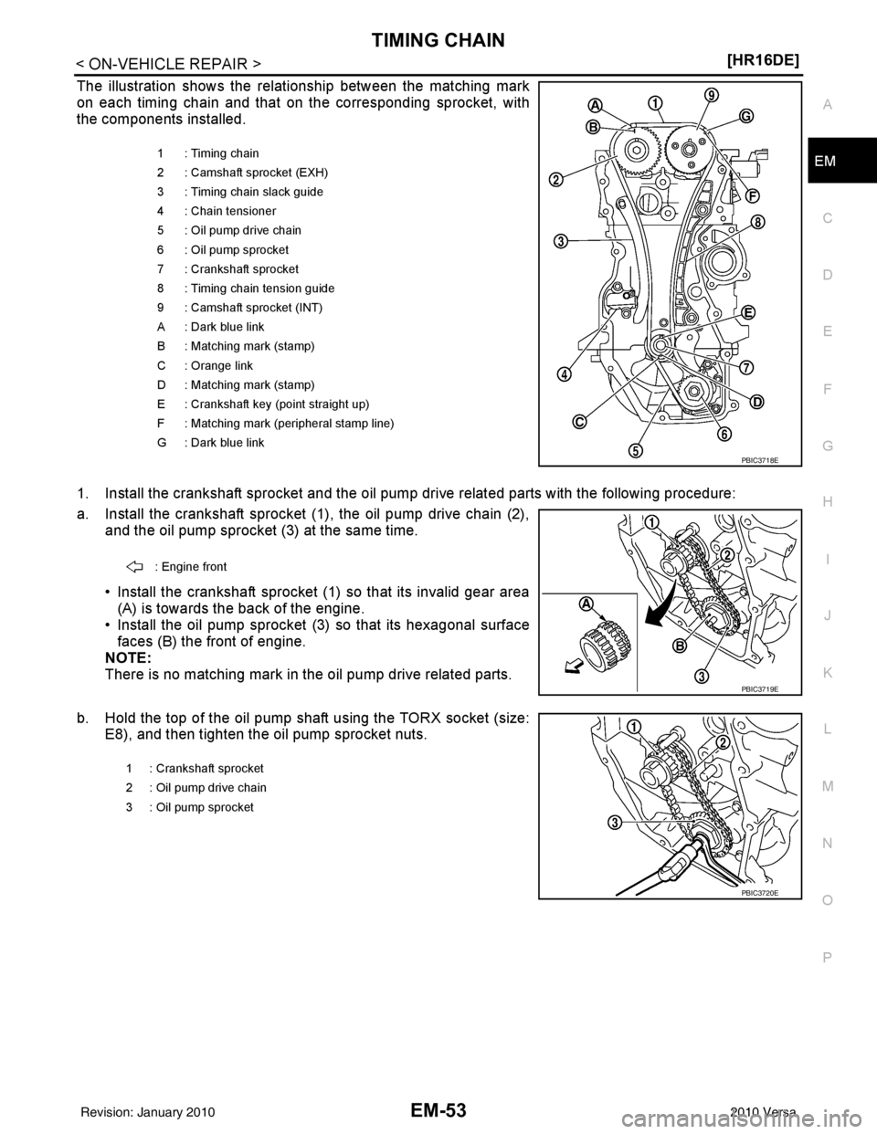
The illustration shows the relationship between the matching mark
on each timing chain and that on the corresponding sprocket, with
the components installed.
1. Install the crankshaft sprocket and the oil pump drive related parts with the following procedure:
a. Install the crankshaft sprocket (1), the oil pump drive chain (2),
and the oil pump sprocket (3) at the same time.
• Install the crankshaft sprocket (1) so that its invalid gear area(A) is towards the back of the engine.
• Install the oil pump sprocket (3) so that its hexagonal surface
faces (B) the front of engine.
NOTE:
There is no matching mark in the oil pump drive related parts.
b. Hold the top of the oil pump shaft using the TORX socket (size: E8), and then tighten the oil pump sprocket nuts.
1 : Timing chain
2 : Camshaft sprocket (EXH)
3 : Timing chain slack guide
4 : Chain tensioner
5 : Oil pump drive chain
6 : Oil pump sprocket
7 : Crankshaft sprocket
8 : Timing chain tension guide
9 : Camshaft sprocket (INT)
A : Dark blue link
B : Matching mark (stamp)
C : Orange link
D : Matching mark (stamp)
E : Crankshaft key (point straight up)
F : Matching mark (peripheral stamp line)
G : Dark blue link
PBIC3718E
: Engine front
PBIC3719E
1 : Crankshaft sprocket
2 : Oil pump drive chain
3 : Oil pump sprocket
PBIC3720E
Revision: January 20102010 Versa
Page 2428 of 3745
CAMSHAFTEM-69
< ON-VEHICLE REPAIR > [HR16DE]
C
D
E
F
G H
I
J
K L
M A
EM
NP
O
b. Remove intake manifold. Refer to EM-28, "Exploded View".
c. Disconnect ignition coil and inject or harness connectors. Refer to EM-46, "
Exploded View".
3. Remove intake valve timing control solenoid valve. Refer to EM-49, "
Exploded View".
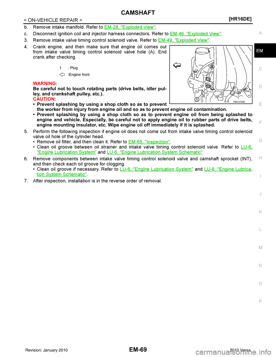
4. Crank engine, and then make sure that engine oil comes out from intake valve timing control solenoid valve hole (A). End
crank after checking.
WARNING:
Be careful not to touch rotating parts (drive belts, idler pul-
ley, and crankshaft pulley, etc.).
CAUTION:
• Prevent splashing by using a shop cloth so as to prevent the worker from injury from engine oil an d so as to prevent engine oil contamination.
• Prevent splashing by using a shop cloth so as to prevent engine oil from being splashed to
engine and vehicle. Especially, be careful not to apply engine oil to rubber parts of drive belts,
engine mounting insulator, etc. Wipe engine oil off immediately if it is splashed.
5. Perform the following inspection if engine oil does not come out from intake valve timing control solenoid
valve oil hole of the cylinder head.
• Remove oil filter, and then clean it. Refer to EM-65, "
Inspection".
• Clean oil groove between oil strainer and intake valve timing control solenoid valve. Refer to LU-6,
"Engine Lubrication System" and LU-6, "Engine Lubrication System Schematic".
6. Remove components between intake valve timing control solenoid valve and camshaft sprocket (INT), and then check each oil groove for clogging.
• Clean oil groove if necessary. Refer to LU-6, "
Engine Lubrication System" and LU-6, "Engine Lubrica-
tion System Schematic".
7. After inspection, installation is in the reverse order of removal.
1: Plug
:Engine front
PBIC3706E
Revision: January 20102010 Versa
Page 2449 of 3745
EM-90
< DISASSEMBLY AND ASSEMBLY >[HR16DE]
CYLINDER BLOCK
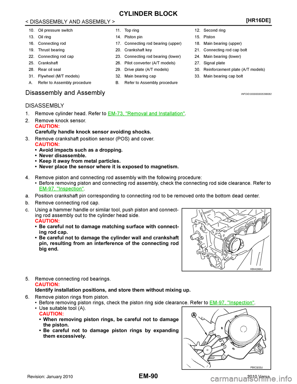
Disassembly and Assembly
INFOID:0000000005398082
DISASSEMBLY
1. Remove cylinder head. Refer to EM-73, "Removal and Installation".
2. Remove knock sensor. CAUTION:
Carefully handle knock sensor avoiding shocks.
3. Remove crankshaft position sensor (POS) and cover. CAUTION:
• Avoid impacts such as a dropping.
• Never disassemble.
• Keep it away from metal particles.
• Never place the sensor where it is exposed to magnetism.
4. Remove piston and connecting rod assembly with the following procedure: • Before removing piston and connecting rod assembly, check the connecting rod side clearance. Refer toEM-97, "
Inspection".
a. Position crankshaft pin corresponding to connecting rod to be removed onto the bottom dead center.
b. Remove connecting rod cap.
c. Using a hammer handle or similar tool, push piston and connect- ing rod assembly out to the cylinder head side.
CAUTION:
• Be careful not to damage matching surface with connect-ing rod cap.
• Be careful not to damage the cylinder wall and crankshaft pin, resulting from an inte rference of the connecting rod
big end.
5. Remove connecting rod bearings. CAUTION:
Identify installation positions, and store them without mixing up.
6. Remove piston rings from piston. • Before removing piston rings, check the piston ring side clearance. Refer to EM-97, "
Inspection".
• Use suitable tool (A).
CAUTION:
• When removing piston rings, be careful not to damagethe piston.
• Be careful not to damage piston rings by expanding
them excessively.
10. Oil pressure switch 11. Top ring12. Second ring
13. Oil ring 14. Piston pin15. Piston
16. Connecting rod 17. Connecting rod bearing (upper) 18. Main bearing (upper)
19. Thrust bearing 20. Crankshaft key21. Connecting rod cap bolt
22. Connecting rod cap 23. Connecting rod bearing (lower) 24. Main bearing (lower)
25. Crankshaft 26. Pilot converter (A/T models) 27. Signal plate
28. Rear oil seal 29. Drive plate (A/T models)30. Reinforcement plate (A/T models)
31. Flywheel (M/T models) 32. Main bearing cap33. Main bearing cap bolt
A. Refer to Assembly procedure B. Refer to Assembly procedure
KBIA3365J
PBIC3233J
Revision: January 20102010 Versa
Page 2467 of 3745
EM-108
< DISASSEMBLY AND ASSEMBLY >[HR16DE]
HOW TO SELECT PISTON AND BEARING
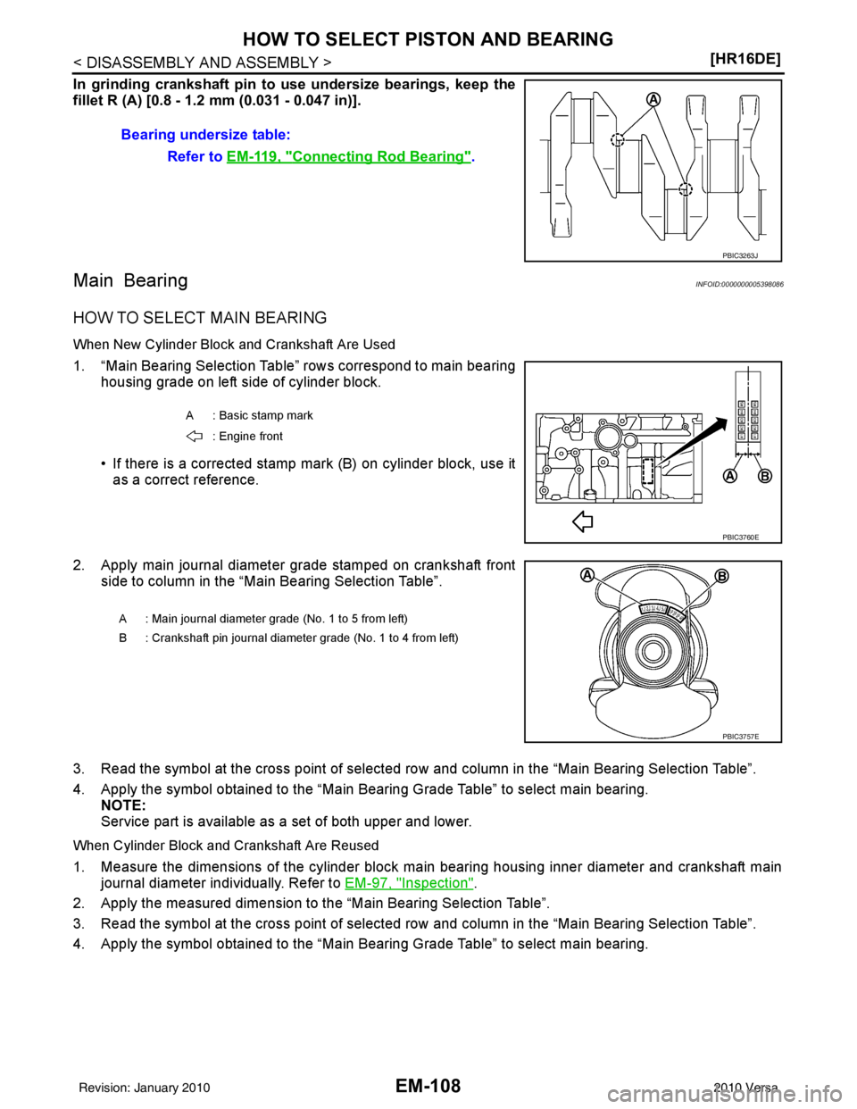
In grinding crankshaft pin to u
se undersize bearings, keep the
fillet R (A) [0.8 - 1.2 mm (0.031 - 0.047 in)].
Main BearingINFOID:0000000005398086
HOW TO SELECT MAIN BEARING
When New Cylinder Block and Crankshaft Are Used
1. “Main Bearing Selection Table” rows correspond to main bearing housing grade on left side of cylinder block.
• If there is a corrected stamp mark (B) on cylinder block, use itas a correct reference.
2. Apply main journal diameter grade stamped on crankshaft front side to column in the “Main Bearing Selection Table”.
3. Read the symbol at the cross point of selected ro w and column in the “Main Bearing Selection Table”.
4. Apply the symbol obtained to the “Main Bearing Grade Table” to select main bearing. NOTE:
Service part is available as a set of both upper and lower.
When Cylinder Block and Crankshaft Are Reused
1. Measure the dimensions of the cylinder block ma in bearing housing inner diameter and crankshaft main
journal diameter individually. Refer to EM-97, "
Inspection".
2. Apply the measured dimension to the “Main Bearing Selection Table”.
3. Read the symbol at the cross point of selected ro w and column in the “Main Bearing Selection Table”.
4. Apply the symbol obtained to the “Main Bearing Grade Table” to select main bearing. Bearing undersize table:
Refer to EM-119, "
Connecting Rod Bearing".
PBIC3263J
A : Basic stamp mark
: Engine front
PBIC3760E
A : Main journal diameter grade (No. 1 to 5 from left)
B : Crankshaft pin journal diameter grade (No. 1 to 4 from left)
PBIC3757E
Revision: January 20102010 Versa
Page 2512 of 3745
FUEL INJECTOR AND FUEL TUBEEM-153
< SERVICE INFORMATION > [MR18DE]
C
D
E
F
G H
I
J
K L
M A
EM
NP
O
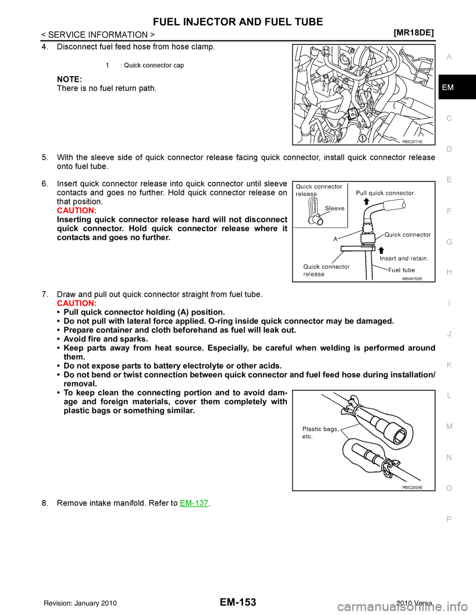
4. Disconnect fuel feed hose from hose clamp.
NOTE:
There is no fuel return path.
5. With the sleeve side of quick connector release facing quick connector, install quick connector release onto fuel tube.
6. Insert quick connector release into quick connector until sleeve contacts and goes no further. Hold quick connector release on
that position.
CAUTION:
Inserting quick connector re lease hard will not disconnect
quick connector. Hold qui ck connector release where it
contacts and goes no further.
7. Draw and pull out quick connector straight from fuel tube. CAUTION:
• Pull quick connector holding (A) position.
• Do not pull with lateral force applied. O-ring inside quick connector may be damaged.
• Prepare container and cloth be forehand as fuel will leak out.
• Avoid fire and sparks.
• Keep parts away from heat source. Especially, be careful when welding is performed around
them.
• Do not expose parts to battery electrolyte or other acids.
• Do not bend or twist connection between quick co nnector and fuel feed hose during installation/
removal.
• To keep clean the connecting portion and to avoid dam-
age and foreign materials, cover them completely with
plastic bags or something similar.
8. Remove intake manifold. Refer to EM-137
.
1 : Quick connector cap
PBIC3771E
KBIA0702E
PBIC2205E
Revision: January 20102010 Versa
Page 2520 of 3745
TIMING CHAINEM-161
< SERVICE INFORMATION > [MR18DE]
C
D
E
F
G H
I
J
K L
M A
EM
NP
O
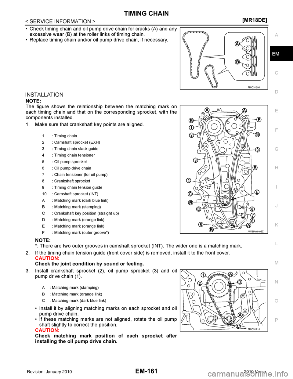
• Check timing chain and oil pump drive chain for cracks (A) and any
excessive wear (B) at the roller links of timing chain.
• Replace timing chain and/or oil pum p drive chain, if necessary.
INSTALLATION
NOTE:
The figure shows the relationship between the matching mark on
each timing chain and that on the corresponding sprocket, with the
components installed.
1. Make sure that crankshaft key points are aligned.
NOTE:
*: There are two outer grooves in camshaft spro cket (INT). The wider one is a matching mark.
2. If the timing chain tension guide (front cover si de) is removed, install it to the front cover.
CAUTION:
Check the joint condition by sound or feeling.
3. Install crankshaft sprocket (2), oil pump sprocket (3) and oil pump drive chain (1).
• Install it by aligning matching marks on each sprocket and oil
pump drive chain.
• If these matching marks are not aligned, rotate the oil pump
shaft slightly to correct the position.
CAUTION:
Check matching mark position of each sprocket after
installing the oil pump drive chain.
PBIC3169J
1 : Timing chain
2 : Camshaft sprocket (EXH)
3 : Timing chain slack guide
4 : Timing chain tensioner
5 : Oil pump sprocket
6 : Oil pump drive chain
7 : Chain tensioner (for oil pump)
8 : Crankshaft sprocket
9 : Timing chain tension guide
10 : Camshaft sprocket (INT)
A : Matching mark (dark blue link)
B : Matching mark (stamping)
C : Crankshaft key position (straight up)
D : Matching mark (orange link)
E : Matching mark (orange link)
F : Matching mark (outer groove*)
A : Matching mark (stamping)
B : Matching mark (orange link)
C : Matching mark (dark blue link)
AWBIA0140ZZ
PBIC3171J
Revision: January 20102010 Versa
Page 2533 of 3745
EM-174
< SERVICE INFORMATION >[MR18DE]
CAMSHAFT
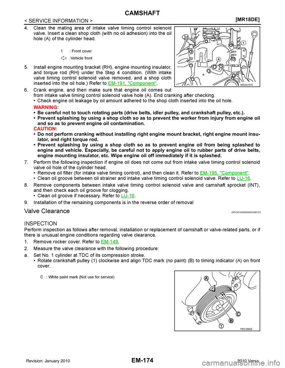
4. Clean the mating area of intake valve timing control solenoid
valve. Insert a clean shop cloth (with no oil adhesion) into the oil
hole (A) of the cylinder head.
5. Install engine mounting bracket (RH), engine mounting insulator, and torque rod (RH) under the Step 4 condition. (With intake
valve timing control solenoid valve removed, and a shop cloth
inserted into the oil hole.) Refer to EM-191, "
Component".
6. Crank engine, and then make sure that engine oil comes out from intake valve timing control solenoid valve hole (A). End cranking after checking.
• Check engine oil leakage by oil amount adhered to the shop cloth inserted into the oil hole.
WARNING:
• Be careful not to touch rotating parts (drive be lts, idler pulley, and crankshaft pulley, etc.).
• Prevent splashing by using a shop cloth so as to prevent the worker from injury from engine oil
and so as to prevent engi ne oil contamination.
CAUTION:
• Do not perform cranking without installing right engine mount bracket, right engine mount insu-
lator, and right torque rod.
• Prevent splashing by using a shop cloth so as to prevent engine oil from being splashed to
engine and vehicle. Especially, be careful not to apply engine oil to rubber parts of drive belts,
engine mounting insulator, etc. Wipe engi ne oil off immediately if it is splashed.
7. Perform the following inspection if engine oil does not come out from intake valve timing control solenoid valve oil hole of the cylinder head.
• Remove oil filter (for intake valve timing control), and then clean it. Refer to EM-195, "
Component".
• Clean oil groove between oil strainer and intake valve timing control solenoid valve. Refer to LU-16
.
8. Remove components between intake valve timing c ontrol solenoid valve and camshaft sprocket (INT),
and then check each oil groove for clogging.
• Clean oil groove if necessary. Refer to LU-16
.
9. Installation of the remaining components is in the reverse order of removal
Valve ClearanceINFOID:0000000005398133
INSPECTION
Perform inspection as follows after removal, installation or replacement of camshaft or valve-related parts, or if
there is unusual engine conditions regarding valve clearance.
1. Remove rocker cover. Refer to EM-149
.
2. Measure the valve clearance with the following procedure:
a. Set No. 1 cylinder at TDC of its compression stroke. • Rotate crankshaft pulley (1) clockwise and align TDC mark (no paint) (B) to timing indicator (A) on front
cover.
1 : Front cover
:Vehicle front
WBIA0781E
C : White paint mark (Not use for service)
PBIC3960E
Revision: January 20102010 Versa
Page 2541 of 3745
EM-182
< SERVICE INFORMATION >[MR18DE]
CYLINDER HEAD
• If the engine speed is out of the specified range, c
heck battery liquid for proper gravity. Check engine
speed again with normal battery gravity.
• If compression pressure is below minimum val ue, check valve clearances and parts associated with
combustion chamber (Valve, valve seat, piston, pi ston ring, cylinder bore, cylinder head, cylinder head
gasket). After the checking, measure the compression pressure again.
• If one cylinder has low compression pressure, pour small amount of engine oil into the spark plug hole
of the cylinder to re-check it for compression.
- If the added engine oil improves the compression, pi ston rings may be worn out or damaged. Check pis-
ton rings and replace if necessary.
- If the compression pressure remains at low level despite the addition of engine oil, valves may be mal- functioning. Check valves for damage. Repl ace valve or valve seat accordingly.
• If two adjacent cylinders have respectively low co mpression pressure and their compression remains
low even after the addition of engine oil, cylinder head gasket is leaking. In such a case, replace cylinder
head gasket.
9. After inspection is completed, install removed parts.
10. Start the engine, and confirm that the engine runs smoothly.
11. Perform trouble diagnosis. If DTC appears, erase it. Refer to EC-585, "
Trouble Diagnosis Introduction".
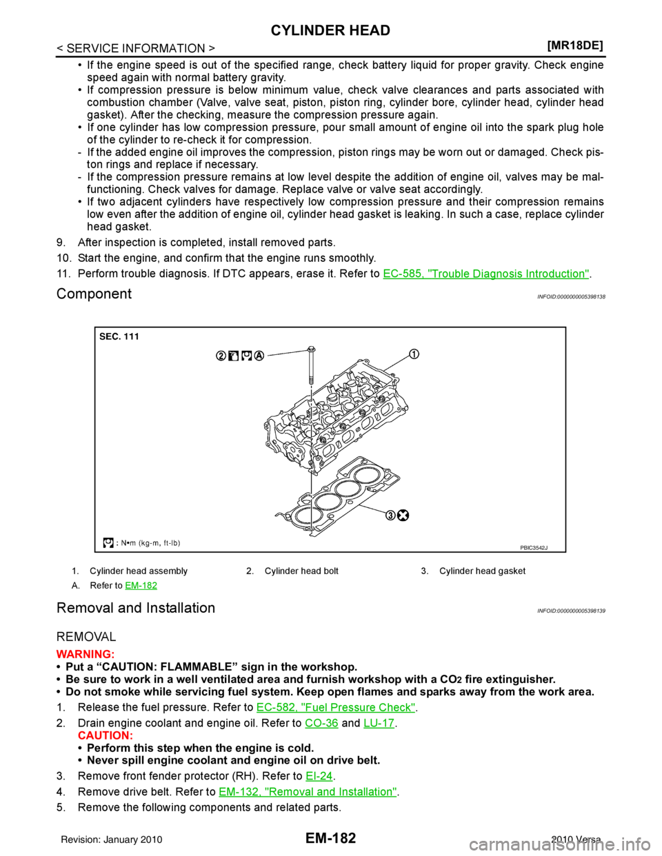
ComponentINFOID:0000000005398138
Removal and InstallationINFOID:0000000005398139
REMOVAL
WARNING:
• Put a “CAUTION: FLAMMABLE” sign in the workshop.
• Be sure to work in a well ventilate d area and furnish workshop with a CO
2 fire extinguisher.
• Do not smoke while servicing fuel system. Keep open flames and sparks away from the work area.
1. Release the fuel pressure. Refer to EC-582, "
Fuel Pressure Check".
2. Drain engine coolant and engine oil. Refer to CO-36
and LU-17.
CAUTION:
• Perform this step when the engine is cold.
• Never spill engine coolant an d engine oil on drive belt.
3. Remove front fender protector (RH). Refer to EI-24
.
4. Remove drive belt. Refer to EM-132, "
Removal and Installation".
5. Remove the following components and related parts.
1. Cylinder head assembly 2. Cylinder head bolt 3. Cylinder head gasket
A. Refer to EM-182
PBIC3542J
Revision: January 20102010 Versa