ESP NISSAN TIIDA 2010 Service Repair Manual
[x] Cancel search | Manufacturer: NISSAN, Model Year: 2010, Model line: TIIDA, Model: NISSAN TIIDA 2010Pages: 3745, PDF Size: 73.67 MB
Page 1883 of 3745
EC-618
< SERVICE INFORMATION >[MR18DE]
TROUBLE DIAGNOSIS
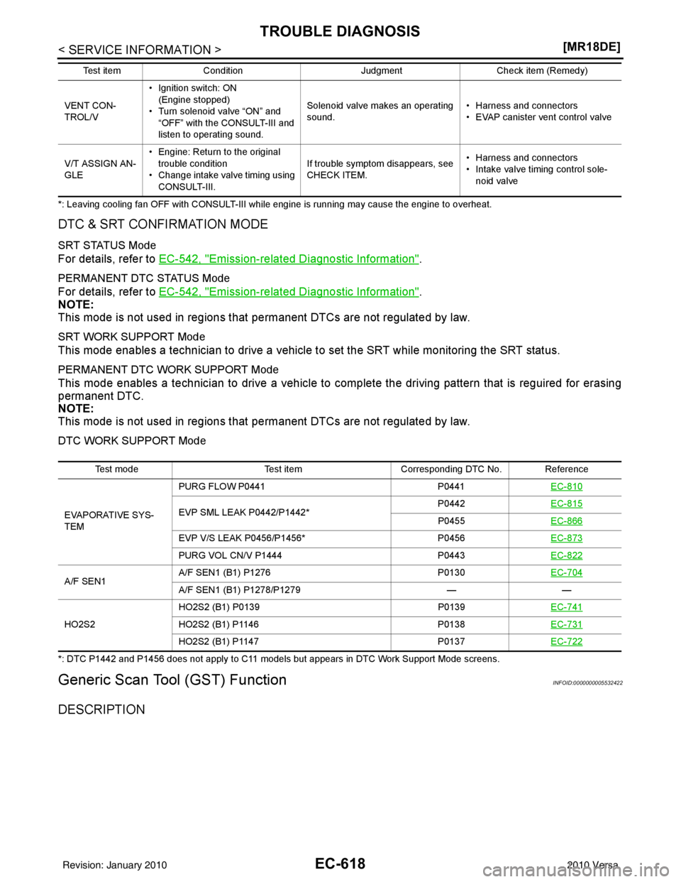
*: Leaving cooling fan OFF with CONSULT-III while engine is running may cause the engine to overheat.
DTC & SRT CONFIRMATION MODE
SRT STATUS Mode
For details, refer to EC-542, "Emission-related Diagnostic Information".
PERMANENT DTC STATUS Mode
For details, refer to
EC-542, "Emission-related Diagnostic Information".
NOTE:
This mode is not used in regions that permanent DTCs are not regulated by law.
SRT WORK SUPPORT Mode
This mode enables a technician to drive a vehicle to set the SRT while monitoring the SRT status.
PERMANENT DTC WORK SUPPORT Mode
This mode enables a technician to drive a vehicle to comp lete the driving pattern that is reguired for erasing
permanent DTC.
NOTE:
This mode is not used in regions that permanent DTCs are not regulated by law.
DTC WORK SUPPORT Mode
*: DTC P1442 and P1456 does not apply to C11 models but appears in DTC Work Support Mode screens.
Generic Scan Tool (GST) FunctionINFOID:0000000005532422
DESCRIPTION
VENT CON-
TROL/V• Ignition switch: ON
(Engine stopped)
• Turn solenoid valve “ON” and “OFF” with the CONSULT-III and
listen to operating sound. Solenoid valve makes an operating
sound.
• Harness and connectors
• EVAP canister vent control valve
V/T ASSIGN AN-
GLE • Engine: Return to the original
trouble condition
• Change intake valve timing using CONSULT-III. If trouble symptom disappears, see
CHECK ITEM.
• Harness and connectors
• Intake valve timing control sole-
noid valve
Test item
Condition JudgmentCheck item (Remedy)
Test mode Test itemCorresponding DTC No. Reference
EVAPORATIVE SYS-
TEM PURG FLOW P0441
P0441EC-810
EVP SML LEAK P0442/P1442* P0442
EC-815P0455EC-866
EVP V/S LEAK P0456/P1456* P0456EC-873
PURG VOL CN/V P1444 P0443EC-822
A/F SEN1 A/F SEN1 (B1) P1276
P0130EC-704A/F SEN1 (B1) P1278/P1279 ——
HO2S2 HO2S2 (B1) P0139
P0139EC-741
HO2S2 (B1) P1146 P0138EC-731
HO2S2 (B1) P1147 P0137EC-722
Revision: January 20102010 Versa
Page 1888 of 3745
TROUBLE DIAGNOSISEC-623
< SERVICE INFORMATION > [MR18DE]
C
D
E
F
G H
I
J
K L
M A
EC
NP
O
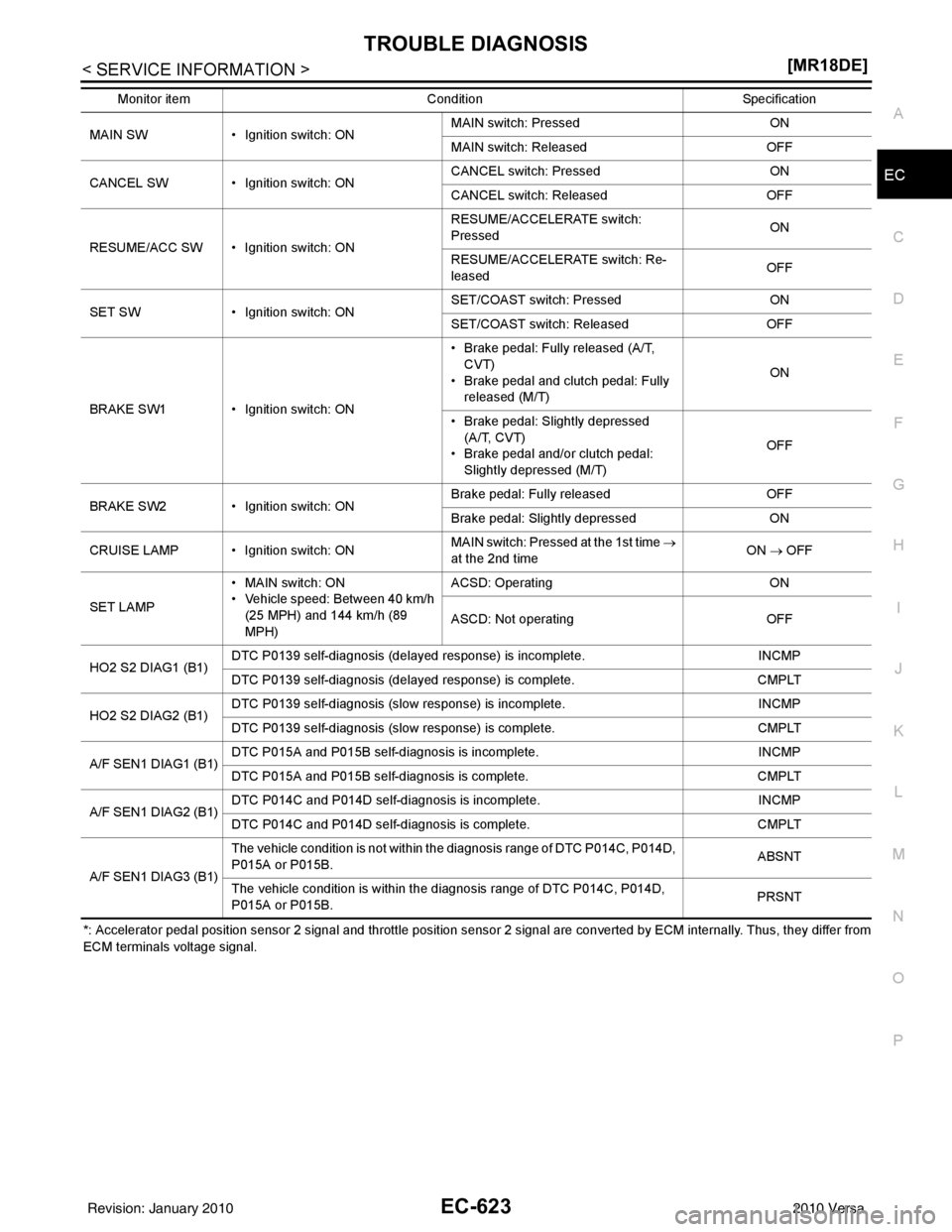
*: Accelerator pedal position sensor 2 signal and throttle position sensor 2 signal are converted by ECM internally. Thus, they
differ from
ECM terminals voltage signal. MAIN SW
• Ignition switch: ON MAIN switch: Pressed
ON
MAIN switch: Released OFF
CANCEL SW • Ignition switch: ON CANCEL switch: Pressed
ON
CANCEL switch: Released OFF
RESUME/ACC SW • Ignition switch: ON RESUME/ACCELERATE switch:
Pressed
ON
RESUME/ACCELERATE switch: Re-
leased OFF
SET SW • Ignition switch: ON SET/COAST switch: Pressed
ON
SET/COAST switch: Released OFF
BRAKE SW1 • Ignition switch: ON • Brake pedal: Fully released (A/T,
CVT)
• Brake pedal and clutch pedal: Fully
released (M/T) ON
• Brake pedal: Slightly depressed (A/T, CVT)
• Brake pedal and/or clutch pedal:
Slightly depressed (M/T) OFF
BRAKE SW2 • Ignition switch: ON Brake pedal: Fully released
OFF
Brake pedal: Slightly depressed ON
CRUISE LAMP • Ignition switch: ON MAIN switch: Pressed at the 1st time
→
at the 2nd time ON
→ OFF
SET LAMP • MAIN switch: ON
• Vehicle speed: Between 40 km/h
(25 MPH) and 144 km/h (89
MPH) ACSD: Operating
ON
ASCD: Not operating OFF
HO2 S2 DIAG1 (B1) DTC P0139 self-diagnosis (delayed response) is incomplete.
INCMP
DTC P0139 self-diagnosis (delayed response) is complete. CMPLT
HO2 S2 DIAG2 (B1) DTC P0139 self-diagnosis (slow
response) is incomplete. INCMP
DTC P0139 self-diagnosis (slo w response) is complete. CMPLT
A/F SEN1 DIAG1 (B1) DTC P015A and P015B self-diagnosis is incomplete.
INCMP
DTC P015A and P015B self-diagnosis is complete. CMPLT
A/F SEN1 DIAG2 (B1) DTC P014C and P014D self-diagnosis is incomplete.
INCMP
DTC P014C and P014D self-diagnosis is complete. CMPLT
A/F SEN1 DIAG3 (B1) The vehicle condition is not within the diagnosis range of DTC P014C, P014D,
P015A or P015B.
ABSNT
The vehicle condition is within the diagnosis range of DTC P014C, P014D,
P015A or P015B. PRSNT
Monitor item
Condition Specification
Revision: January 20102010 Versa
Page 1893 of 3745
EC-628
< SERVICE INFORMATION >[MR18DE]
TROUBLE DIAGNOSIS - SPECIFICATION VALUE
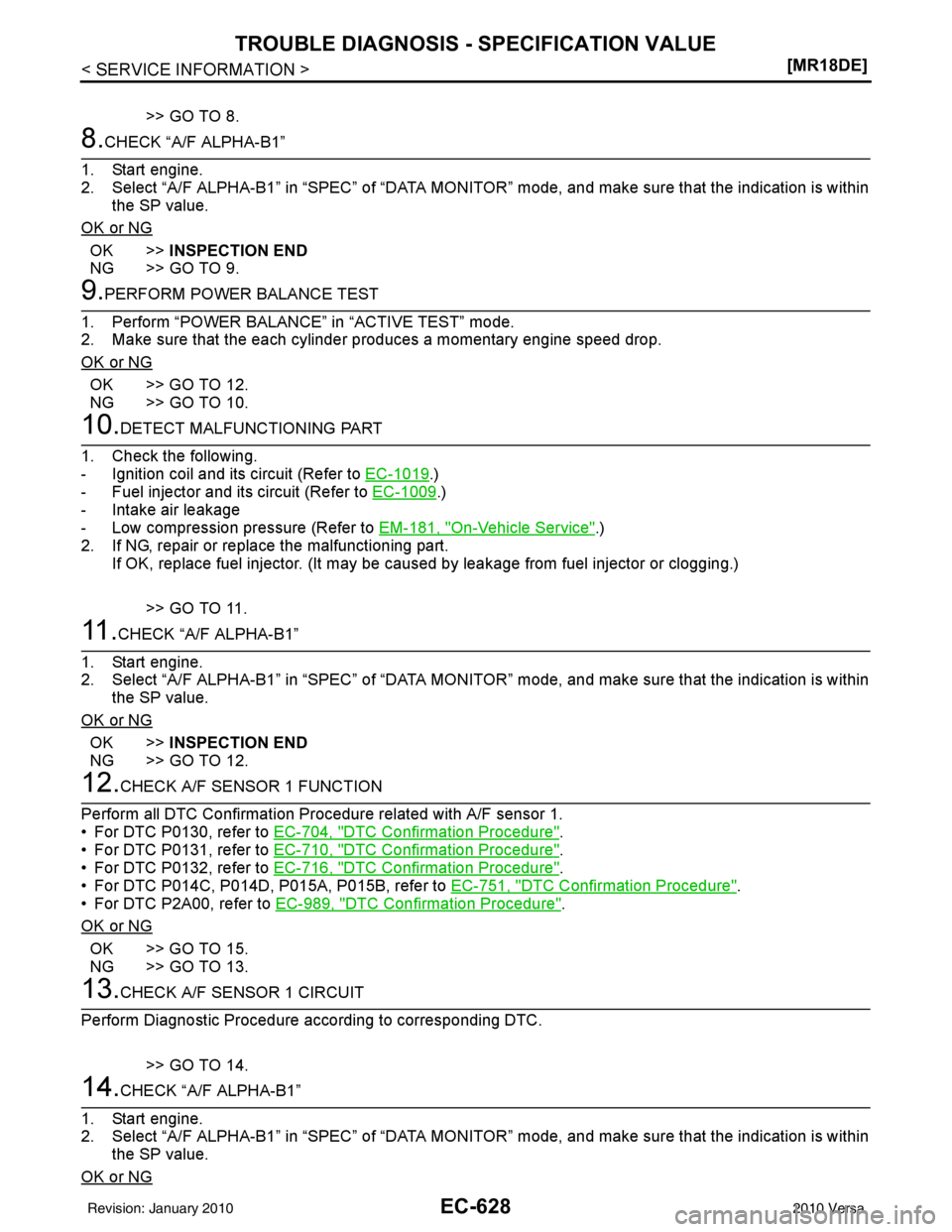
>> GO TO 8.
8.CHECK “A/F ALPHA-B1”
1. Start engine.
2. Select “A/F ALPHA-B1” in “SPEC” of “DATA MONITO R” mode, and make sure that the indication is within
the SP value.
OK or NG
OK >> INSPECTION END
NG >> GO TO 9.
9.PERFORM POWER BALANCE TEST
1. Perform “POWER BALANCE” in “ACTIVE TEST” mode.
2. Make sure that the each cylinder produces a momentary engine speed drop.
OK or NG
OK >> GO TO 12.
NG >> GO TO 10.
10.DETECT MALFUNCTIONING PART
1. Check the following.
- Ignition coil and its circuit (Refer to EC-1019
.)
- Fuel injector and its circuit (Refer to EC-1009
.)
- Intake air leakage
- Low compression pressure (Refer to EM-181, "
On-Vehicle Service".)
2. If NG, repair or replace the malfunctioning part. If OK, replace fuel injector. (It may be caus ed by leakage from fuel injector or clogging.)
>> GO TO 11.
11 .CHECK “A/F ALPHA-B1”
1. Start engine.
2. Select “A/F ALPHA-B1” in “SPEC” of “DATA MONITO R” mode, and make sure that the indication is within
the SP value.
OK or NG
OK >> INSPECTION END
NG >> GO TO 12.
12.CHECK A/F SENSOR 1 FUNCTION
Perform all DTC Confirmation Procedure related with A/F sensor 1.
• For DTC P0130, refer to EC-704, "
DTC Confirmation Procedure".
• For DTC P0131, refer to EC-710, "
DTC Confirmation Procedure".
• For DTC P0132, refer to EC-716, "
DTC Confirmation Procedure".
• For DTC P014C, P014D, P015A, P015B, refer to EC-751, "
DTC Confirmation Procedure".
• For DTC P2A00, refer to EC-989, "
DTC Confirmation Procedure".
OK or NG
OK >> GO TO 15.
NG >> GO TO 13.
13.CHECK A/F SENSOR 1 CIRCUIT
Perform Diagnostic Procedure according to corresponding DTC.
>> GO TO 14.
14.CHECK “A/F ALPHA-B1”
1. Start engine.
2. Select “A/F ALPHA-B1” in “SPEC” of “DATA MONITO R” mode, and make sure that the indication is within
the SP value.
OK or NG
Revision: January 20102010 Versa
Page 1914 of 3745
DTC P0031, P0032 A/F SENSOR 1 HEATEREC-649
< SERVICE INFORMATION > [MR18DE]
C
D
E
F
G H
I
J
K L
M A
EC
NP
O
DTC P0031, P0032 A/F SENSOR 1 HEATER
DescriptionINFOID:0000000005532455
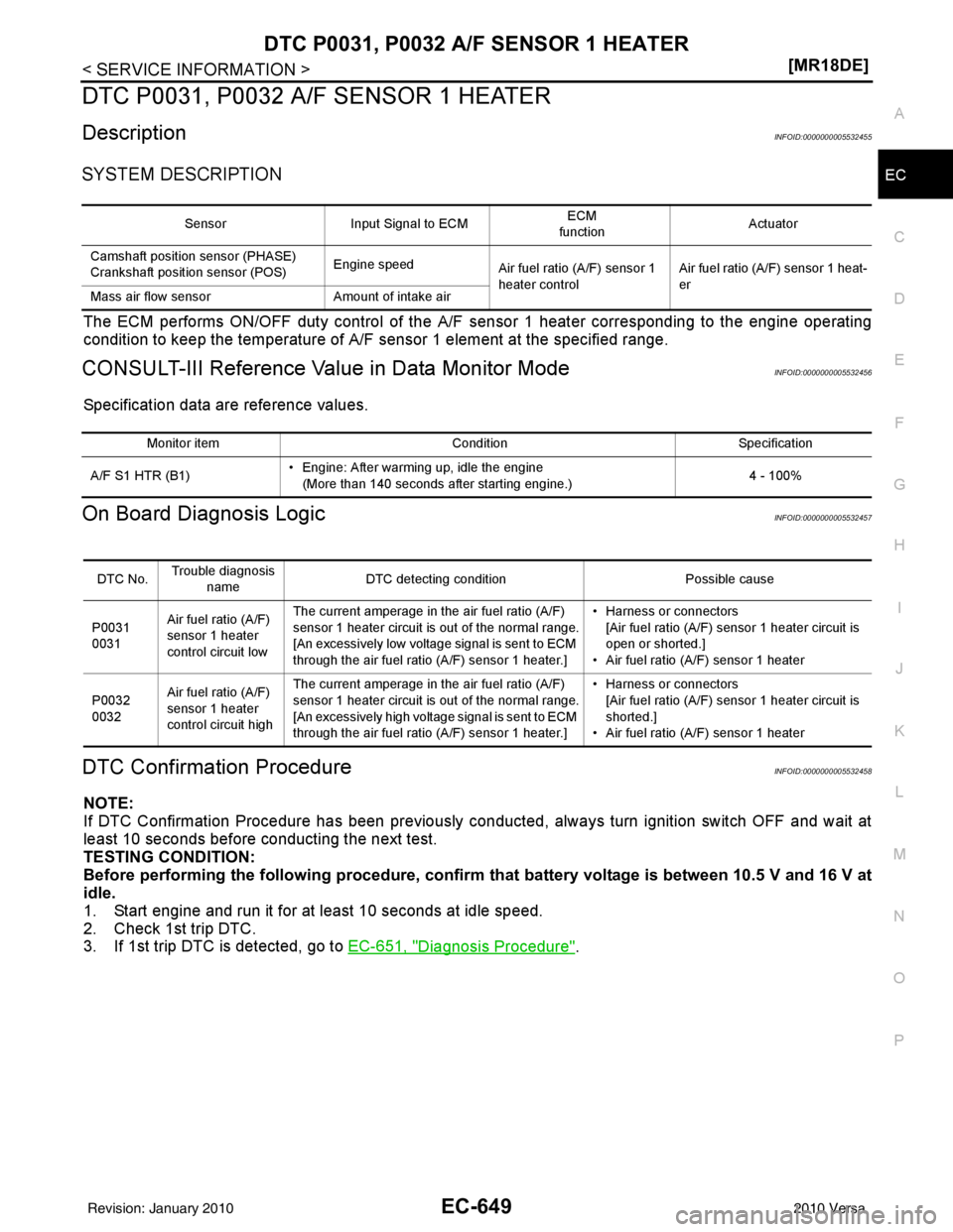
SYSTEM DESCRIPTION
The ECM performs ON/OFF duty control of the A/F
sensor 1 heater corresponding to the engine operating
condition to keep the temperature of A/F sensor 1 element at the specified range.
CONSULT-III Reference Val ue in Data Monitor ModeINFOID:0000000005532456
Specification data are reference values.
On Board Diagnosis LogicINFOID:0000000005532457
DTC Confirmation ProcedureINFOID:0000000005532458
NOTE:
If DTC Confirmation Procedure has been previously conducted, always turn ignition switch OFF and wait at
least 10 seconds before conducting the next test.
TESTING CONDITION:
Before performing the following pr ocedure, confirm that battery voltage is between 10.5 V and 16 V at
idle.
1. Start engine and run it for at least 10 seconds at idle speed.
2. Check 1st trip DTC.
3. If 1st trip DTC is detected, go to EC-651, "
Diagnosis Procedure".
SensorInput Signal to ECM ECM
function Actuator
Camshaft position sensor (PHASE)
Crankshaft position sensor (POS) Engine speed
Air fuel ratio (A/F) sensor 1
heater control Air fuel ratio (A/F) sensor 1 heat-
er
Mass air flow sensor Amount of intake air
Monitor item ConditionSpecification
A/F S1 HTR (B1) • Engine: After warming up, idle the engine
(More than 140 seconds after starting engine.) 4 - 100%
DTC No.Trouble diagnosis
name DTC detecting condition
Possible cause
P0031
0031 Air fuel ratio (A/F)
sensor 1 heater
control circuit low The current amperage in
the air fuel ratio (A/F)
sensor 1 heater circuit is out of the normal range.
[An excessively low voltage signal is sent to ECM
through the air fuel ratio (A/F) sensor 1 heater.] • Harness or connectors
[Air fuel ratio (A/F) sensor 1 heater circuit is
open or shorted.]
• Air fuel ratio (A/F) sensor 1 heater
P0032
0032 Air fuel ratio (A/F)
sensor 1 heater
control circuit high The current amperage in
the air fuel ratio (A/F)
sensor 1 heater circuit is out of the normal range.
[An excessively high voltage signal is sent to ECM
through the air fuel ratio (A/F) sensor 1 heater.] • Harness or connectors
[Air fuel ratio (A/F) sensor 1 heater circuit is
shorted.]
• Air fuel ratio (A/F) sensor 1 heater
Revision: January 20102010 Versa
Page 1919 of 3745
EC-654
< SERVICE INFORMATION >[MR18DE]
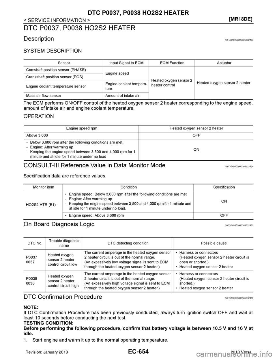
DTC P0037, P0038 HO2S2 HEATER
DTC P0037, P0038 HO2S2 HEATER
DescriptionINFOID:0000000005532463
SYSTEM DESCRIPTION
The ECM performs ON/OFF control of the heated oxy
gen sensor 2 heater corresponding to the engine speed,
amount of intake air and engine coolant temperature.
OPERATION
CONSULT-III Reference Value in Data Monitor ModeINFOID:0000000005532464
Specification data are reference values.
On Board Diagn osis LogicINFOID:0000000005532465
DTC Confirmation ProcedureINFOID:0000000005532466
NOTE:
If DTC Confirmation Procedure has been previously conducted, always turn ignition switch OFF and wait at
least 10 seconds before conducting the next test.
TESTING CONDITION:
Before performing the following procedure, confi rm that battery voltage is between 10.5 V and 16 V at
idle.
1. Start engine and warm it up to the normal operating temperature.
Sensor Input Signal to ECM ECM Function Actuator
Camshaft position sensor (PHASE) Engine speed
Heated oxygen sensor 2
heater controlHeated oxygen sensor 2 heater
Crankshaft position sensor (POS)
Engine coolant temperature sensor
Engine coolant tempera-
ture
Mass air flow sensor Amount of intake air
Engine speed rpm Heated oxygen sensor 2 heater
Above 3,600 OFF
• Below 3,600 rpm after the following conditions are met.
- Engine: After warming up
- Keeping the engine speed between 3,500 and 4,000 rpm for 1 minute and at idle for 1 minute under no load ON
Monitor item
Condition Specification
HO2S2 HTR (B1) • Engine speed: Below 3,600 rpm after the following conditions are met
- Engine: After warming up
- Keeping the engine speed between 3,500 and 4,000 rpm for 1 minute and
at idle for 1 minute under no load. ON
• Engine speed: Above 3,600 rpm OFF
DTC No.Trouble diagnosis
name DTC detecting condition
Possible cause
P0037
0037 Heated oxygen
sensor 2 heater
control circuit low The current amperage in the heated oxygen sensor
2 heater circuit is out of the normal range.
(An excessively low voltage signal is sent to ECM
through the heated oxygen sensor 2 heater.) • Harness or connectors
(Heated oxygen sensor 2 heater circuit is
open or shorted.)
• Heated oxygen sensor 2 heater
P0038
0038 Heated oxygen
sensor 2 heater
control circuit high The current amperage in the heated oxygen sensor
2 heater circuit is out of the normal range.
(An excessively high voltage signal is sent to ECM
through the heated oxygen sensor 2 heater.) • Harness or connectors
(Heated oxygen sensor 2 heater circuit is
shorted.)
• Heated oxygen sensor 2 heater
Revision: January 20102010 Versa
Page 1930 of 3745
DTC P0101 MAF SENSOREC-665
< SERVICE INFORMATION > [MR18DE]
C
D
E
F
G H
I
J
K L
M A
EC
NP
O
PROCEDURE FOR MALFUNCTION A
NOTE:
If engine will not start or stops soon, wait at leas
t 10 seconds with engine stopped (Ignition switch ON) instead
of running engine at idle speed.
1. Start engine and warm it up to normal operating temperature.
2. Run engine for at least 10 seconds at idle speed.
3. Check 1st trip DTC.
4. If 1st trip DTC is detected, go to EC-668, "
Diagnosis Procedure".
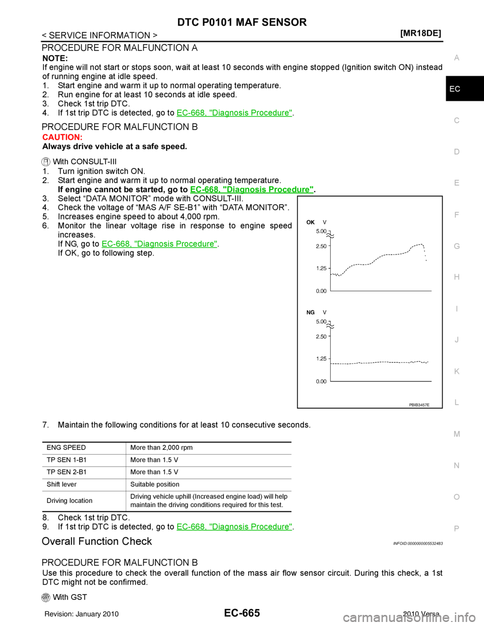
PROCEDURE FOR MALFUNCTION B
CAUTION:
Always drive vehicle at a safe speed.
With CONSULT-III
1. Turn ignition switch ON.
2. Start engine and warm it up to normal operating temperature.
If engine cannot be started, go to EC-668, "
Diagnosis Procedure".
3. Select “DATA MONITOR” mode with CONSULT-III.
4. Check the voltage of “MAS A/F SE-B1” with “DATA MONITOR”.
5. Increases engine speed to about 4,000 rpm.
6. Monitor the linear voltage rise in response to engine speed increases.
If NG, go to EC-668, "
Diagnosis Procedure".
If OK, go to following step.
7. Maintain the following conditions for at least 10 consecutive seconds.
8. Check 1st trip DTC.
9. If 1st trip DTC is detected, go to EC-668, "
Diagnosis Procedure".
Overall Function CheckINFOID:0000000005532483
PROCEDURE FOR MALFUNCTION B
Use this procedure to check the overall function of the ma ss air flow sensor circuit. During this check, a 1st
DTC might not be confirmed.
With GST
PBIB3457E
ENG SPEED More than 2,000 rpm
TP SEN 1-B1 More than 1.5 V
TP SEN 2-B1 More than 1.5 V
Shift lever Suitable position
Driving location Driving vehicle uphill (Increased engine load) will help
maintain the driving conditions required for this test.
Revision: January 20102010 Versa
Page 1931 of 3745
EC-666
< SERVICE INFORMATION >[MR18DE]
DTC P0101 MAF SENSOR
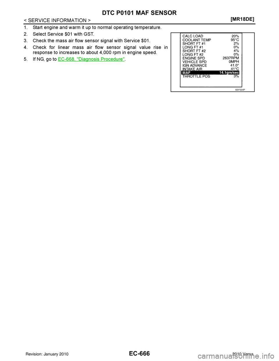
1. Start engine and warm it up to normal operating temperature.
2. Select Service $01 with GST.
3. Check the mass air flow sensor signal with Service $01.
4. Check for linear mass air flow sensor signal value rise in
response to increases to about 4,000 rpm in engine speed.
5. If NG, go to EC-668, "
Diagnosis Procedure".
SEF534P
Revision: January 20102010 Versa
Page 1935 of 3745
EC-670
< SERVICE INFORMATION >[MR18DE]
DTC P0101 MAF SENSOR
2. Also check harness for short to ground and short to power.
OK or NG
OK >> GO TO 8.
NG >> Repair open circuit or short to ground or short or short to power in harness or connectors.
8.CHECK INTAKE AIR TEMPERATURE SENSOR
Refer to EC-682, "
Component Inspection".
OK or NG
OK >> GO TO 9.
NG >> Replace intake air temperature sensor.
9.CHECK EVAP CONTROL SY STEM PRESSURE SENSOR
Refer to EC-850, "
Component Inspection".
OK or NG
OK >> GO TO 10.
NG >> Replace EVAP control system pressure sensor.
10.CHECK MASS AIR FLOW SENSOR
Refer to EC-670, "
Component Inspection".
OK or NG
OK >> GO TO 11.
NG >> Replace mass air flow sensor.
11 .CHECK INTERMITTENT INCIDENT
Perform EC-632
.
>> INSPECTION END
Component InspectionINFOID:0000000005532486
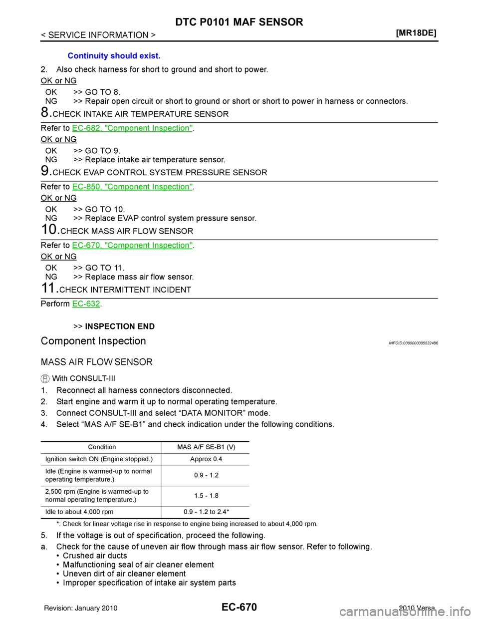
MASS AIR FLOW SENSOR
With CONSULT-III
1. Reconnect all harness connectors disconnected.
2. Start engine and warm it up to normal operating temperature.
3. Connect CONSULT-III and select “DATA MONITOR” mode.
4. Select “MAS A/F SE-B1” and check i ndication under the following conditions.
*: Check for linear voltage rise in response to engine being increased to about 4,000 rpm.
5. If the voltage is out of specification, proceed the following.
a. Check for the cause of uneven air flow through mass air flow sensor. Refer to following. • Crushed air ducts
• Malfunctioning seal of air cleaner element
• Uneven dirt of air cleaner element
• Improper specification of intake air system partsContinuity should exist.
Condition
MAS A/F SE-B1 (V)
Ignition switch ON (Engine stopped.) Approx 0.4
Idle (Engine is warmed-up to normal
operating temperature.) 0.9 - 1.2
2,500 rpm (Engine is warmed-up to
normal operating temperature.) 1.5 - 1.8
Idle to about 4,000 rpm 0.9 - 1.2 to 2.4*
Revision: January 20102010 Versa
Page 1936 of 3745
DTC P0101 MAF SENSOREC-671
< SERVICE INFORMATION > [MR18DE]
C
D
E
F
G H
I
J
K L
M A
EC
NP
O
b. If NG, repair or replace malfunctioning part and perform step 2 to 4 again.
If OK, go to next step.
6. Turn ignition switch OFF.
7. Disconnect mass air flow sensor har ness connector and reconnect it again.
8. Perform step 2 to 4 again.
9. If NG, clean or replace mass air flow sensor.
Without CONSULT-III
1. Reconnect all harness connectors disconnected.
2. Start engine and warm it up to normal operating temperature.
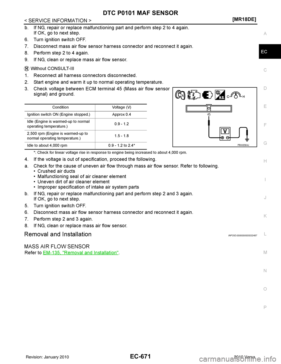
3. Check voltage between ECM terminal 45 (Mass air flow sensor signal) and ground.
*: Check for linear voltage rise in response to engine being increased to about 4,000 rpm.
4. If the voltage is out of spec ification, proceed the following.
a. Check for the cause of uneven air flow through mass air flow sensor. Refer to following. • Crushed air ducts
• Malfunctioning seal of air cleaner element
• Uneven dirt of air cleaner element
• Improper specification of intake air system parts
b. If NG, repair or replace malfunctioning part and perform step 2 and 3 again. If OK, go to next step.
5. Turn ignition switch OFF.
6. Disconnect mass air flow sensor har ness connector and reconnect it again.
7. Perform step 2 and 3 again.
8. If NG, clean or replace mass air flow sensor.
Removal and InstallationINFOID:0000000005532487
MASS AIR FLOW SENSOR
Refer to EM-135, "Removal and Installation".
Condition Voltage (V)
Ignition switch ON (Engine stopped.) Approx 0.4
Idle (Engine is warmed-up to normal
operating temperature.) 0.9 - 1.2
2,500 rpm (Engine is warmed-up to
normal operating temperature.) 1.5 - 1.8
Idle to about 4,000 rpm 0.9 - 1.2 to 2.4*
PBIA9564J
Revision: January 20102010 Versa
Page 1942 of 3745
DTC P0102, P0103 MAF SENSOREC-677
< SERVICE INFORMATION > [MR18DE]
C
D
E
F
G H
I
J
K L
M A
EC
NP
O
2. Also check harness for short to ground and short to power.
OK or NG
OK >> GO TO 8.
NG >> Repair open circuit or short to ground or short to power in harness or connectors.
8.CHECK MASS AIR FLOW SENSOR
Refer to EC-677, "
Component Inspection".
OK or NG
OK >> GO TO 9.
NG >> Replace mass air flow sensor.
9.CHECK INTERMITTENT INCIDENT
Refer to EC-632
.
>> INSPECTION END
Component InspectionINFOID:0000000005532494
MASS AIR FLOW SENSOR
With CONSULT-III
1. Reconnect all harness connectors disconnected.
2. Start engine and warm it up to normal operating temperature.
3. Connect CONSULT-III and select “DATA MONITOR” mode.
4. Select “MAS A/F SE-B1” and check i ndication under the following conditions.
*: Check for linear voltage rise in response to engine being increased to about 4,000 rpm.
5. If the voltage is out of specification, proceed the following.
a. Check for the cause of uneven air flow through mass air flow sensor. Refer to following. • Crushed air ducts
• Malfunctioning seal of air cleaner element
• Uneven dirt of air cleaner element
• Improper specification of intake air system parts
b. If NG, repair or replace malfunctioning part and perform step 2 to 4 again. If OK, go to next step.
6. Turn ignition switch OFF.
7. Disconnect mass air flow sensor har ness connector and reconnect it again.
8. Perform step 2 to 4 again.
9. If NG, clean or replace mass air flow sensor.
Without CONSULT-III
1. Reconnect all harness connectors disconnected.
2. Start engine and warm it up to normal operating temperature. Continuity should exist.
Condition
MAS A/F SE-B1 (V)
Ignition switch ON (Engine stopped.) Approx 0.4
Idle (Engine is warmed-up to normal
operating temperature.) 0.9 - 1.2
2,500 rpm (Engine is warmed-up to
normal operating temperature.) 1.5 - 1.8
Idle to about 4,000 rpm 0.9 - 1.2 to 2.4*
Revision: January 20102010 Versa