NISSAN TIIDA 2010 Service Repair Manual
Manufacturer: NISSAN, Model Year: 2010, Model line: TIIDA, Model: NISSAN TIIDA 2010Pages: 3745, PDF Size: 73.67 MB
Page 191 of 3745
AT-174
< SERVICE INFORMATION >
TR SW, OD SW AND CLOSED THROTTLE, WIDE OPEN THROTTLE POSITION
SIGNAL CIRCUIT
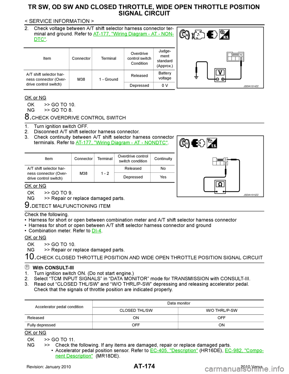
2. Check voltage between A/T shift selector harness connector ter-
minal and ground. Refer to AT-177, "
Wiring Diagram - AT - NON-
DTC".
OK or NG
OK >> GO TO 10.
NG >> GO TO 8.
8.CHECK OVERDRIVE CONTROL SWITCH
1. Turn ignition switch OFF.
2. Disconnect A/T shift selector harness connector.
3. Check continuity between A/T shift selector harness connector terminals. Refer to AT-177, "
Wiring Diagram - AT - NONDTC".
OK or NG
OK >> GO TO 9.
NG >> Repair or replace damaged parts.
9.DETECT MALFUNCTIONING ITEM
Check the following.
• Harness for short or open between combination meter and A/T shift selector harness connector
• Harness for short or open between A/T shift selector harness connector and ground
• Combination meter. Refer to DI-4
.
OK or NG
OK >> GO TO 10.
NG >> Repair or replace damaged parts.
10.CHECK CLOSED THROTTLE POSI TION AND WIDE OPEN THROTTLE POSITION SIGNAL CIRCUIT
With CONSULT-III
1. Turn ignition switch ON. (Do not start engine.)
2. Select “TCM INPUT SIGNALS” in “DATA MONITOR” mode for TRANSMISSION with CONSULT-III.
3. Read out “CLOSED THL/SW” and “W/O THRL/P-S W” depressing and releasing accelerator pedal.
Check that the signals of throttle position are indicated properly.
OK or NG
OK >> GO TO 11.
NG >> Check the following. If any items are damaged, repair or replace damaged parts. • Accelerator pedal position sensor. Refer to EC-405, "
Description" (HR16DE), EC-982, "Compo-
nent Description" (MR18DE).
Item Connector Terminal Overdrive
control switch
Condition Judge-
ment
standard
(Approx.)
A/T shift selector har-
ness connector (Over-
drive control switch) M38 1 - Ground
Released
Battery
voltage
Depressed 0 V
JSDIA1514ZZ
Item Connector Terminal Overdrive control
switch condition Continuity
A/T shift selector har-
ness connector (Over-
drive control switch) M38 1 - 2
Released No
Depressed Yes
JSDIA1515ZZ
Accelerator pedal condition Data monitor
CLOSED THL/SW W/O THRL/P-SW
Released ONOFF
Fully depressed OFFON
Revision: January 20102010 Versa
Page 192 of 3745
TR SW, OD SW AND CLOSED THROTTLE, WIDE OPEN THROTTLE POSITION
SIGNAL CIRCUIT
AT-175
< SERVICE INFORMATION >
DE
F
G H
I
J
K L
M A
B
AT
N
O P
11 .PERFORM SELF-DIAGNOSIS
Without CONSULT-III
Perform self-diagnosis. Refer to AT-82, "
Diagnosis Procedure without CONSULT-III".
OK or NG
OK >> INSPECTION END
NG − 1 >> Self-diagnosis does not activate: GO TO 12.
NG − 2 >> DTC is displayed: Check the malfunctioning system. Refer to AT-82, "
Diagnosis Procedure with-
out CONSULT-III".
12.CHECK TCM
1. Check TCM input/output signal. Refer to AT-75, "
TCM Terminal and Reference Value".
2. If NG, recheck TCM pin terminals for dam age or loose connection with harness connector.
OK or NG
OK >> INSPECTION END
NG >> Repair or replace damaged parts.
Component InspectionINFOID:0000000005397388
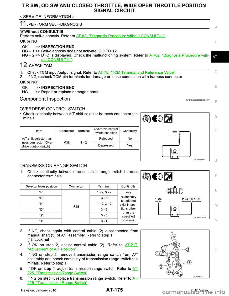
OVERDRIVE CONTROL SWITCH
• Check continuity between A/T shift selector harness connector ter- minals.
TRANSMISSION RANGE SWITCH
1. Check continuity between transmission range switch harness connector terminals.
2. If NG, check again with control cable (2) disconnected from manual shaft (3) of A/T assembly. Refer to step 1.
(1): Lock nut
3. If OK on step 2, adjust control cable (2). Refer to AT-217,
"Adjustment of A/T Position".
4. If NG on step 2, remove transmission range switch from A/T assembly and check continuity of transmission range switch ter-
minals. Refer to step 1.
5. If OK on step 4, adjust transmission range switch. Refer to AT-
225, "Transmission Range Switch".
6. If NG on step 4, replace transmission range switch. Refer to AT-
225, "Transmission Range Switch".
ItemConnector Terminal Overdrive control
switch condition Continuity
A/T shift selector har-
ness connector (Over-
drive control switch) M38 1 - 2Released No
Depressed Yes
JSDIA1515ZZ
Selector lever position Connector Terminal Continuity “P”
F251 - 2, 3 - 7
Ye s
*Continuity
should not
exist in posi- tions other
than the
specified
positions.
“R”
3 - 8
“N” 1 - 2, 3 - 9
“D” 3 - 6
“2” 3 - 5
“1” 3 - 4
JSDIA1503GB
SCIA6370J
Revision: January 20102010 Versa
Page 193 of 3745
AT-176
< SERVICE INFORMATION >
SHIFT POSITION INDICATOR CIRCUIT
SHIFT POSITION INDICATOR CIRCUIT
DescriptionINFOID:0000000005397389
TCM sends the switch signals to combination meter via CAN communication line. Then selector lever position
is indicated on the shift position indicator.
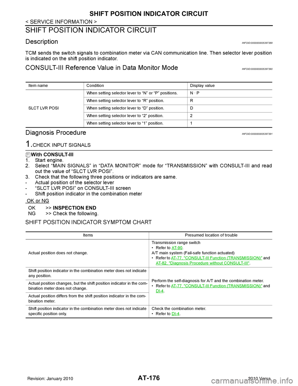
CONSULT-III Reference Value in Data Monitor ModeINFOID:0000000005397390
Diagnosis ProcedureINFOID:0000000005397391
1.CHECK INPUT SIGNALS
With CONSULT-III
1. Start engine.
2. Select “MAIN SIGNALS” in “DATA MONITOR” m ode for “TRANSMISSION” with CONSULT-III and read
out the value of “SLCT LVR POSI”.
3. Check that the following three pos itions or indicators are same.
- Actual position of the selector lever
- “SLCT LVR POSI” on CONSULT-III screen
- Shift position indicator in the combination meter
OK or NG
OK >> INSPECTION END
NG >> Check the following.
SHIFT POSITION INDICATOR SYMPTOM CHART
Item name Condition Display value
SLCT LVR POSI When setting selector lever to
“N” or “P” positions. N · P
When setting selector lever to “R” position. R
When setting selector lever to “D” position. D
When setting selector lever to “2” position. 2
When setting selector lever to “1” position. 1
ItemsPresumed location of trouble
Actual position does not change. Transmission range switch
• Refer to
AT- 9 0
.
A/T main system (Fail-safe function actuated)
•Refer to AT- 7 7 , "
CONSULT-III Function (TRANSMISSION)" and
AT- 8 2 , "
Diagnosis Procedure without CONSULT-III".
Shift position indicator in the combination meter does not indicate
any position. Perform the self-diagnosis for A/T and the combination meter.
•Refer to AT- 7 7 , "
CONSULT-III Function (TRANSMISSION)" and
DI-4
.
Actual position changes, but the shift position indicator in the com-
bination meter does not change.
Actual position differs from the shift position indicator in the com-
bination meter.
Shift position indicator in the combination meter does not indicate
specific position only.
Check the combination meter.
• Refer to
DI-4
.
Revision: January 20102010 Versa
Page 194 of 3745
TROUBLE DIAGNOSIS FOR SYMPTOMSAT-177
< SERVICE INFORMATION >
DE
F
G H
I
J
K L
M A
B
AT
N
O P
TROUBLE DIAGNOSIS FOR SYMPTOMS
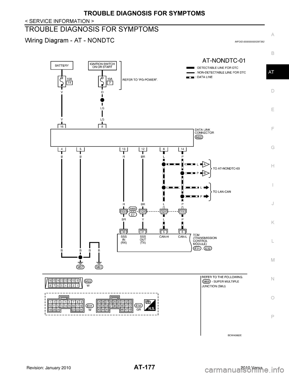
Wiring Diagram - AT - NONDTCINFOID:0000000005397392
BCWA0662E
Revision: January 20102010 Versa
Page 195 of 3745
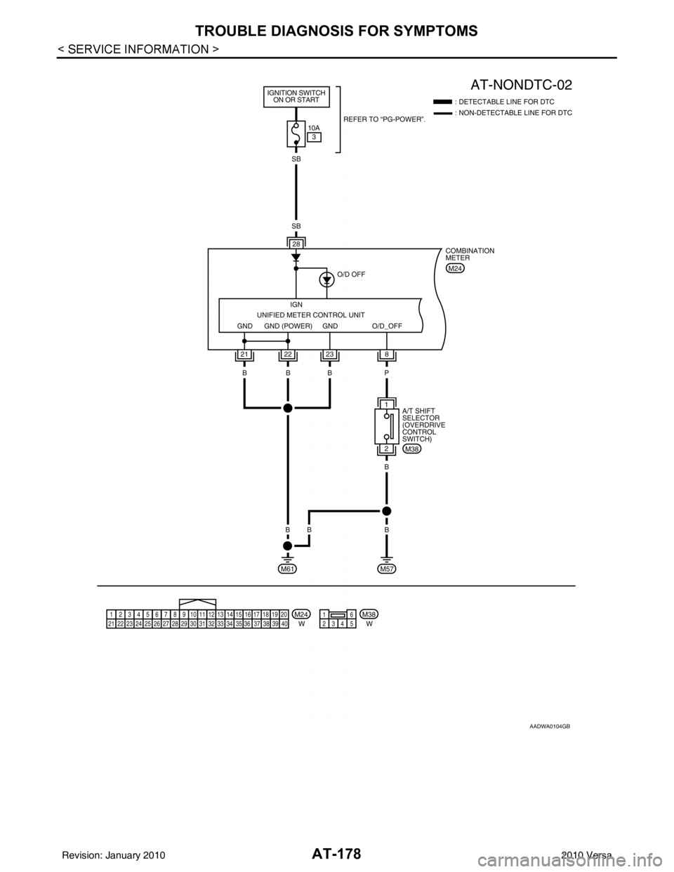
AT-178
< SERVICE INFORMATION >
TROUBLE DIAGNOSIS FOR SYMPTOMS
AADWA0104GB
Revision: January 20102010 Versa
Page 196 of 3745
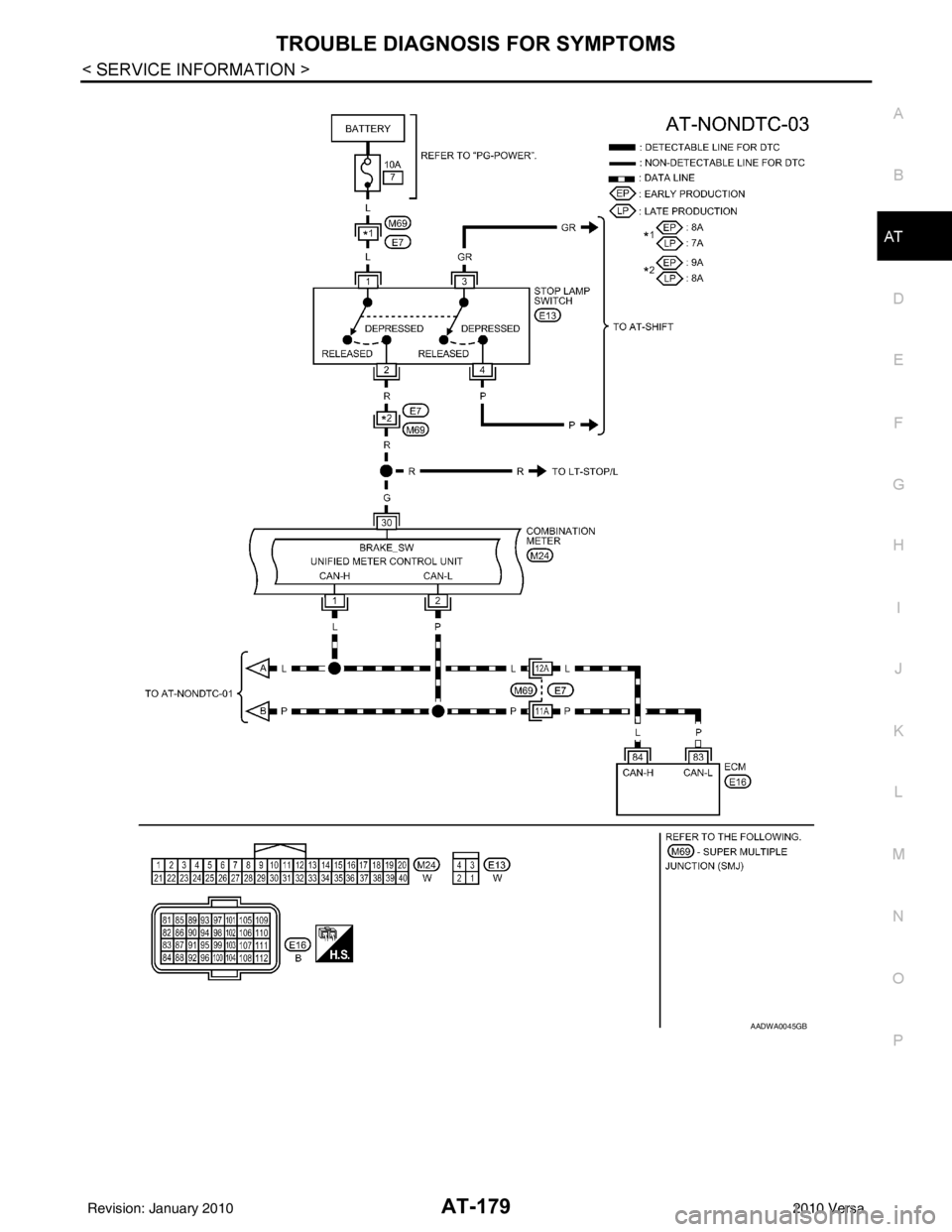
TROUBLE DIAGNOSIS FOR SYMPTOMSAT-179
< SERVICE INFORMATION >
DE
F
G H
I
J
K L
M A
B
AT
N
O P
AADWA0045GB
Revision: January 20102010 Versa
Page 197 of 3745
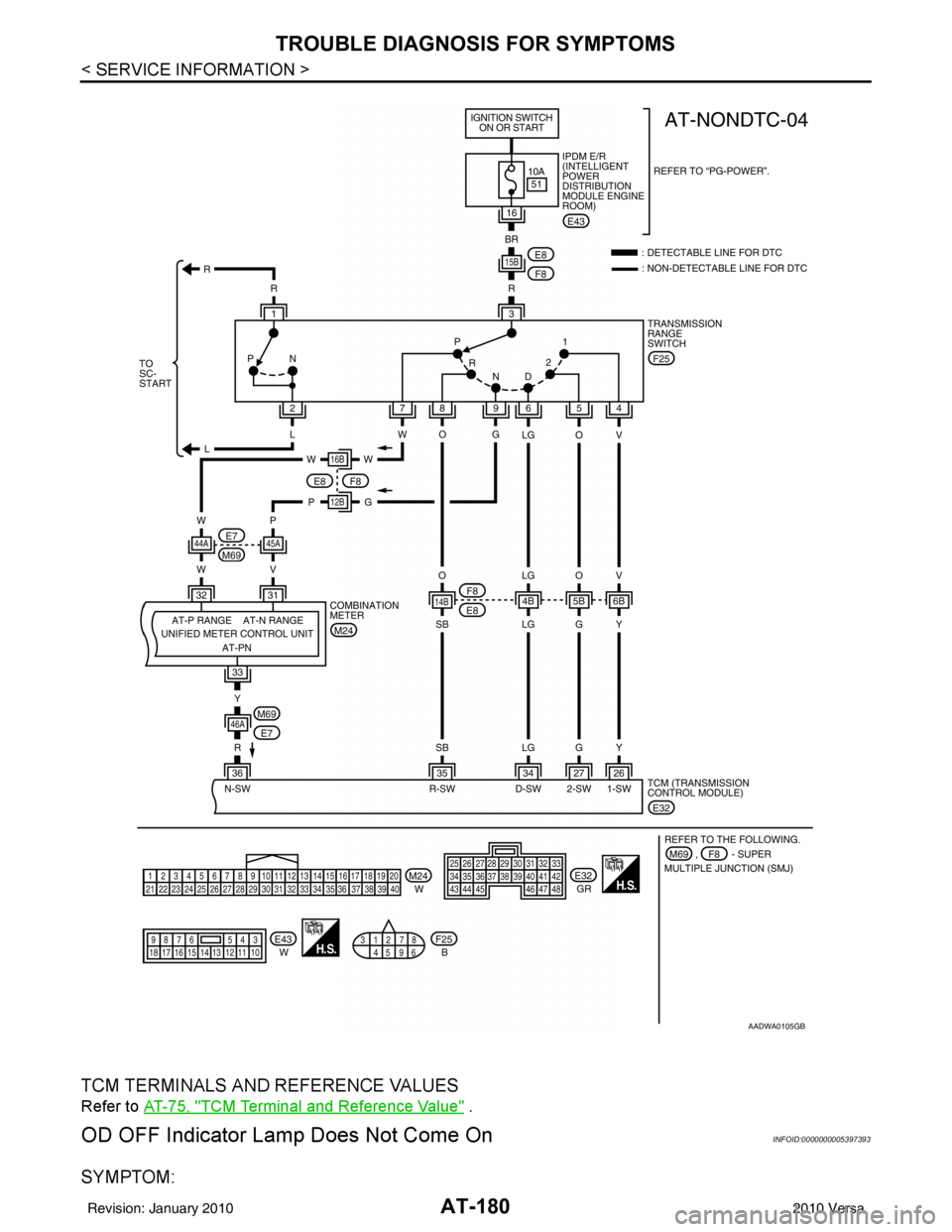
AT-180
< SERVICE INFORMATION >
TROUBLE DIAGNOSIS FOR SYMPTOMS
TCM TERMINALS AND REFERENCE VALUES
Refer to AT-75, "TCM Terminal and Reference Value" .
OD OFF Indicator Lamp Does Not Come OnINFOID:0000000005397393
SYMPTOM:
AADWA0105GB
Revision: January 20102010 Versa
Page 198 of 3745
TROUBLE DIAGNOSIS FOR SYMPTOMSAT-181
< SERVICE INFORMATION >
DE
F
G H
I
J
K L
M A
B
AT
N
O P
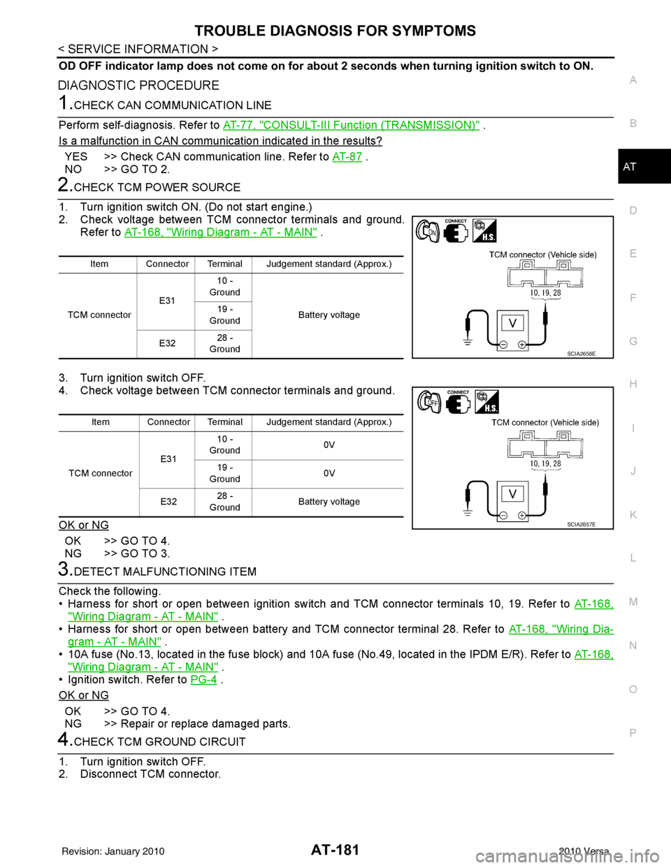
OD OFF indicator lamp does not come on for abou t 2 seconds when turning ignition switch to ON.
DIAGNOSTIC PROCEDURE
1.CHECK CAN COMMUNICATION LINE
Perform self-diagnosis. Refer to AT-77, "
CONSULT-III Function (TRANSMISSION)" .
Is a malfunction in CAN communication indicated in the results?
YES >> Check CAN communication line. Refer to AT- 8 7 .
NO >> GO TO 2.
2.CHECK TCM POWER SOURCE
1. Turn ignition switch ON. (Do not start engine.)
2. Check voltage between TCM connector terminals and ground. Refer to AT-168, "
Wiring Diagram - AT - MAIN" .
3. Turn ignition switch OFF.
4. Check voltage between TCM connector terminals and ground.
OK or NG
OK >> GO TO 4.
NG >> GO TO 3.
3.DETECT MALFUNCTIONING ITEM
Check the following.
• Harness for short or open between ignition switch and TCM connector terminals 10, 19. Refer to AT-168,
"Wiring Diagram - AT - MAIN" .
• Harness for short or open between battery and TCM connector terminal 28. Refer to AT-168, "
Wiring Dia-
gram - AT - MAIN" .
• 10A fuse (No.13, located in the fuse block) and 10A fuse (No.49, located in the IPDM E/R). Refer to AT-168,
"Wiring Diagram - AT - MAIN" .
• Ignition switch. Refer to PG-4
.
OK or NG
OK >> GO TO 4.
NG >> Repair or replace damaged parts.
4.CHECK TCM GROUND CIRCUIT
1. Turn ignition switch OFF.
2. Disconnect TCM connector.
Item Connector Terminal Judgement standard (Approx.)
TCM connector E3110 -
Ground
Battery voltage
19 -
Ground
E32 28 -
Ground
SCIA2656E
Item Connector Terminal Judgement standard (Approx.)
TCM connector E3110 -
Ground 0V
19 -
Ground 0V
E32 28 -
Ground Battery voltage
SCIA2657E
Revision: January 20102010 Versa
Page 199 of 3745
AT-182
< SERVICE INFORMATION >
TROUBLE DIAGNOSIS FOR SYMPTOMS
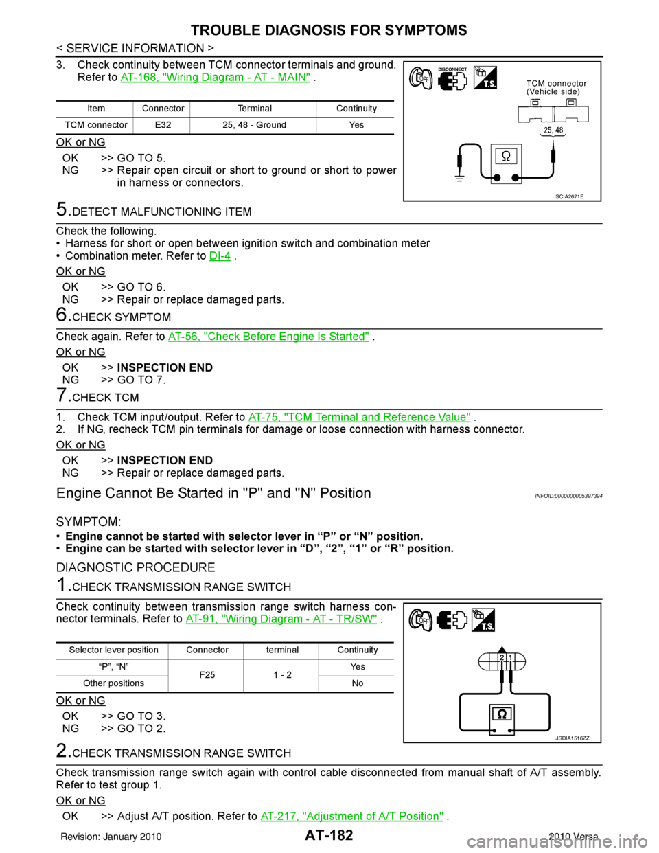
3. Check continuity between TCM connector terminals and ground.Refer to AT-168, "
Wiring Diagram - AT - MAIN" .
OK or NG
OK >> GO TO 5.
NG >> Repair open circuit or short to ground or short to power in harness or connectors.
5.DETECT MALFUNCTIONING ITEM
Check the following.
• Harness for short or open between ignition switch and combination meter
• Combination meter. Refer to DI-4
.
OK or NG
OK >> GO TO 6.
NG >> Repair or replace damaged parts.
6.CHECK SYMPTOM
Check again. Refer to AT-56, "
Check Before Engine Is Started" .
OK or NG
OK >> INSPECTION END
NG >> GO TO 7.
7.CHECK TCM
1. Check TCM input/output. Refer to AT-75, "
TCM Terminal and Reference Value" .
2. If NG, recheck TCM pin terminals for damage or loose connection with harness connector.
OK or NG
OK >> INSPECTION END
NG >> Repair or replace damaged parts.
Engine Cannot Be Started in "P" and "N" PositionINFOID:0000000005397394
SYMPTOM:
•Engine cannot be started with select or lever in “P” or “N” position.
• Engine can be started with selector lever in “D”, “2”, “1” or “R” position.
DIAGNOSTIC PROCEDURE
1.CHECK TRANSMISSION RANGE SWITCH
Check continuity between transmission range switch harness con-
nector terminals. Refer to AT-91, "
Wiring Diagram - AT - TR/SW" .
OK or NG
OK >> GO TO 3.
NG >> GO TO 2.
2.CHECK TRANSMISSION RANGE SWITCH
Check transmission range switch again with control cabl e disconnected from manual shaft of A/T assembly.
Refer to test group 1.
OK or NG
OK >> Adjust A/T position. Refer to AT-217, "Adjustment of A/T Position" .
Item ConnectorTerminalContinuity
TCM connector E32 25, 48 - GroundYes
SCIA2671E
Selector lever position Connector terminal Continuity
“P”, “N” F251 - 2 Ye s
Other positions No
JSDIA1516ZZ
Revision: January 20102010 Versa
Page 200 of 3745
TROUBLE DIAGNOSIS FOR SYMPTOMSAT-183
< SERVICE INFORMATION >
DE
F
G H
I
J
K L
M A
B
AT
N
O P
NG >> 1. Check transmission range switch (Refer to test group 1.) again after adjusting transmission
range switch (Refer to AT-225
).
- If OK, INSPECTION END
- If NG, repair or replace transmission range switch. Refer to AT-225, "
Transmission Range
Switch" .
3.CHECK STARTING SYSTEM
Check starting system. Refer to SC-9
.
OK or NG
OK >> INSPECTION END
NG >> Repair or replace damaged parts.
In "P" Position, Vehicle Moves Forward or Backward When PushedINFOID:0000000005397395
SYMPTOM:
Vehicle moves when it is pushed forward or backward with selector lever in “P” position.
DIAGNOSTIC PROCEDURE
1.CHECK A/T POSITION
Check A/T position. Refer to AT-217, "
Checking of A/T Position" .
OK or NG
OK >> GO TO 2.
NG >> Adjust A/T position. Refer to AT-217, "
Adjustment of A/T Position" .
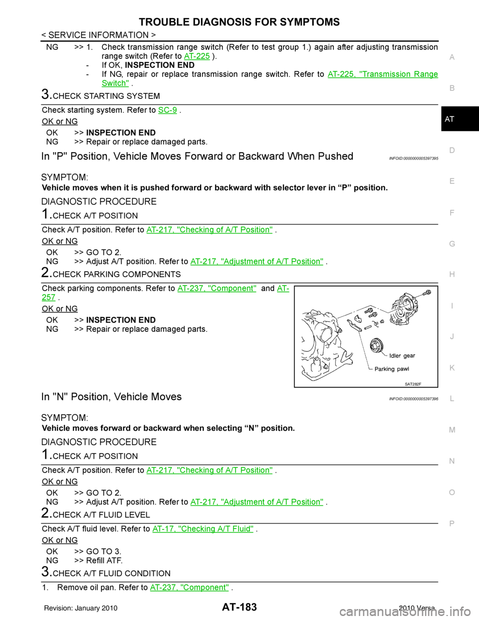
2.CHECK PARKING COMPONENTS
Check parking components. Refer to AT-237, "
Component" and AT-
257 .
OK or NG
OK >> INSPECTION END
NG >> Repair or replace damaged parts.
In "N" Position, Vehicle MovesINFOID:0000000005397396
SYMPTOM:
Vehicle moves forward or backwar d when selecting “N” position.
DIAGNOSTIC PROCEDURE
1.CHECK A/T POSITION
Check A/T position. Refer to AT-217, "
Checking of A/T Position" .
OK or NG
OK >> GO TO 2.
NG >> Adjust A/T position. Refer to AT-217, "
Adjustment of A/T Position" .
2.CHECK A/T FLUID LEVEL
Check A/T fluid level. Refer to AT-17, "
Checking A/T Fluid" .
OK or NG
OK >> GO TO 3.
NG >> Refill ATF.
3.CHECK A/T FLUID CONDITION
1. Remove oil pan. Refer to AT-237, "
Component" .
SAT282F
Revision: January 20102010 Versa