differential NISSAN TIIDA 2010 Service Workshop Manual
[x] Cancel search | Manufacturer: NISSAN, Model Year: 2010, Model line: TIIDA, Model: NISSAN TIIDA 2010Pages: 3745, PDF Size: 73.67 MB
Page 3191 of 3745
PREPARATIONMT-7
< SERVICE INFORMATION > [RS5F91R]
D
E
F
G H
I
J
K L
M A
B
MT
N
O P
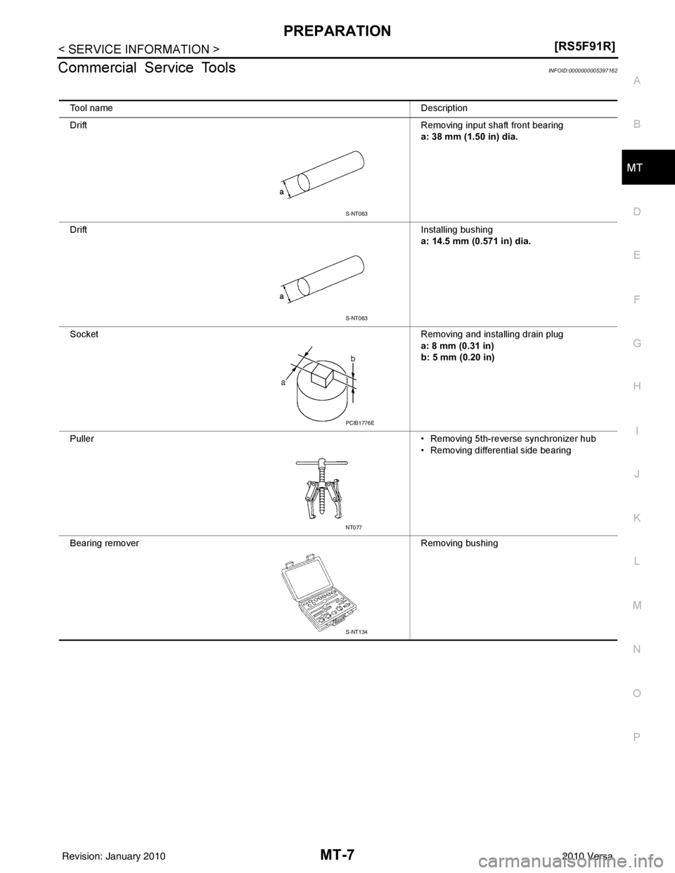
Commercial Service ToolsINFOID:0000000005397162
Tool name Description
Drift Removing input shaft front bearing
a: 38 mm (1.50 in) dia.
Drift Installing bushing
a: 14.5 mm (0.571 in) dia.
Socket Removing and installing drain plug
a: 8 mm (0.31 in)
b: 5 mm (0.20 in)
Puller • Removing 5th-reverse synchronizer hub
• Removing differential side bearing
Bearing remover Removing bushing
S-NT063
S-NT063
PCIB1776E
NT077
S-NT134
Revision: January 20102010 Versa
Page 3193 of 3745
DESCRIPTIONMT-9
< SERVICE INFORMATION > [RS5F91R]
D
E
F
G H
I
J
K L
M A
B
MT
N
O P
DESCRIPTION
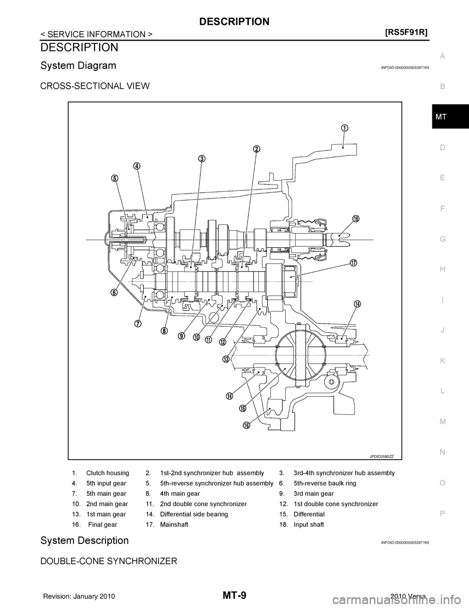
System DiagramINFOID:0000000005397164
CROSS-SECTIONAL VIEW
System DescriptionINFOID:0000000005397165
DOUBLE-CONE SYNCHRONIZER
1. Clutch housing 2. 1st-2nd synchronizer hub assembly 3. 3rd-4th synchronizer hub assembly
4. 5th input gear 5. 5th-reverse synchronizer hub assembly 6. 5th-reverse baulk ring
7. 5th main gear 8. 4th main gear 9. 3rd main gear
10. 2nd main gear 11. 2nd double cone synchronizer 12. 1st double cone synchronizer
13. 1st main gear 14. Differential side bearing 15. Differential
16. Final gear 17. Mainshaft 18. Input shaft
JPDIC0580ZZ
Revision: January 20102010 Versa
Page 3196 of 3745
MT-12
< SERVICE INFORMATION >[RS5F91R]
SIDE OIL SEAL
SIDE OIL SEAL
Removal and InstallationINFOID:0000000005397169
REMOVAL
1. Remove front drive shafts from transaxle assembly. Refer to
FAX-9, "Removal and Installation (Left Side)"
and FAX-10, "Removal and Installation (Right Side)".
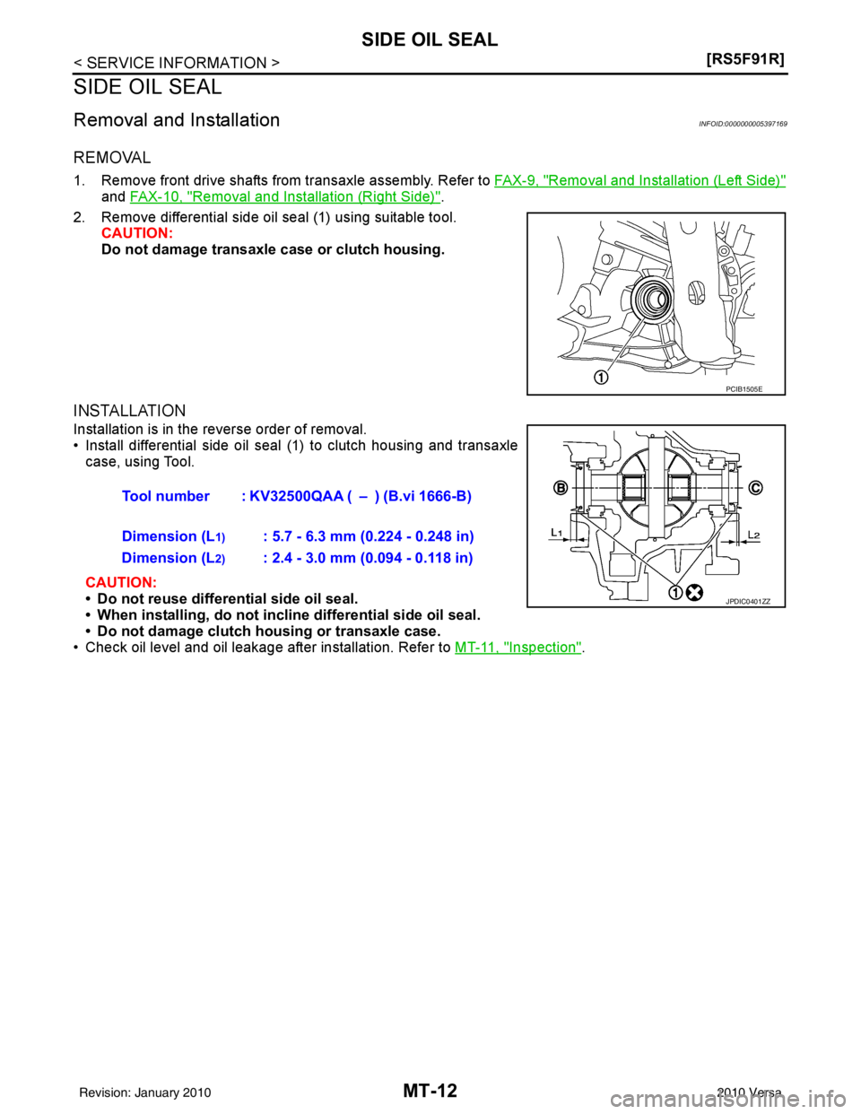
2. Remove differential side oil seal (1) using suitable tool. CAUTION:
Do not damage transaxle case or clutch housing.
INSTALLATION
Installation is in the reverse order of removal.
• Install differential side oil seal (1) to clutch housing and transaxlecase, using Tool.
CAUTION:
• Do not reuse differential side oil seal.
• When installing, do not incl ine differential side oil seal.
• Do not damage clutch housing or transaxle case.
• Check oil level and oil leakage after installation. Refer to MT-11, "
Inspection".
PCIB1505E
Tool number : KV32500QAA ( – ) (B.vi 1666-B)
Dimension (L
1): 5.7 - 6.3 mm (0.224 - 0.248 in)
Dimension (L
2): 2.4 - 3.0 mm (0.094 - 0.118 in)
JPDIC0401ZZ
Revision: January 20102010 Versa
Page 3203 of 3745
TRANSAXLE ASSEMBLYMT-19
< SERVICE INFORMATION > [RS5F91R]
D
E
F
G H
I
J
K L
M A
B
MT
N
O P
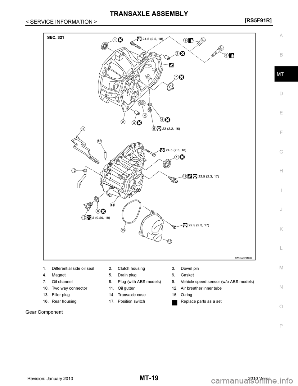
Gear Component
1. Differential side oil seal 2. Clutch housing
3. Dowel pin
4. Magnet 5. Drain plug6. Gasket
7. Oil channel 8. Plug (with ABS models) 9. Vehicle speed sensor (w/o ABS models)
10. Two way connector 11. Oil gutter12. Air breather inner tube
13. Filler plug 14. Transaxle case15. O-ring
16. Rear housing 17. Position switch Replace parts as a set
AWDIA0791GB
Revision: January 20102010 Versa
Page 3206 of 3745
MT-22
< SERVICE INFORMATION >[RS5F91R]
TRANSAXLE ASSEMBLY
DISASSEMBLY
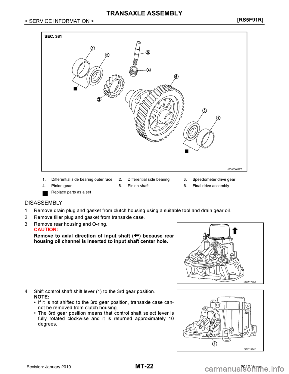
1. Remove drain plug and gasket from clutch housing using a suitable tool and drain gear oil.
2. Remove filler plug and gasket from transaxle case.
3. Remove rear housing and O-ring.
CAUTION:
Remove to axial direction of input shaft ( ) because rear
housing oil channel is inserte d to input shaft center hole.
4. Shift control shaft shift lever (1) to the 3rd gear position. NOTE:
• If it is not shifted to the 3rd gear position, transaxle case can-
not be removed from clutch housing.
• The 3rd gear position means that control shaft select lever is
fully rotated clockwise and it is returned approximately 10
degrees.
1. Differential side bearing outer race 2. Differential side bearing 3. Speedometer drive gear
4. Pinion gear 5. Pinion shaft 6. Final drive assembly
Replace parts as a set
JPDIC0602ZZ
SCIA1709J
PCIB1524E
Revision: January 20102010 Versa
Page 3210 of 3745
MT-26
< SERVICE INFORMATION >[RS5F91R]
TRANSAXLE ASSEMBLY
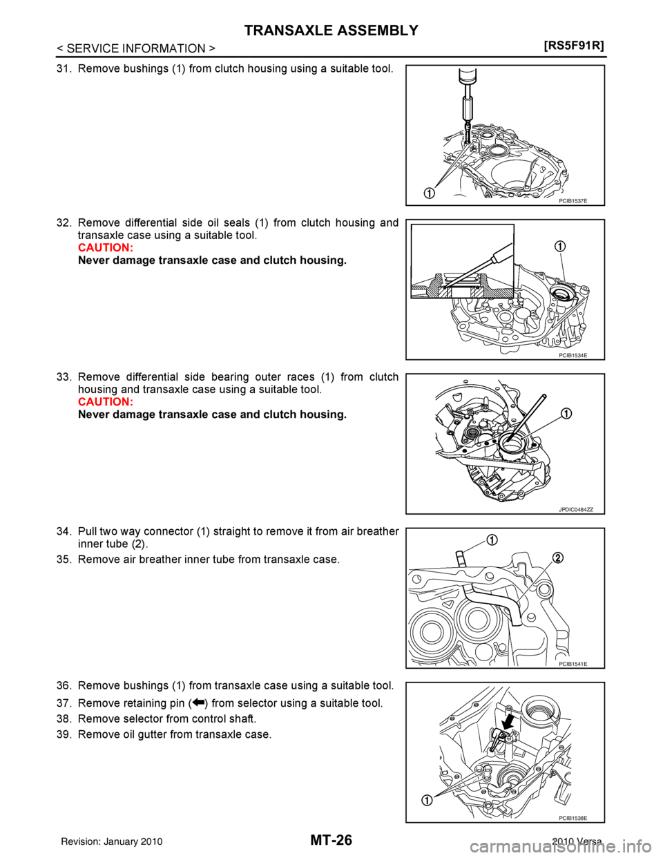
31. Remove bushings (1) from clutch housing using a suitable tool.
32. Remove differential side oil seals (1) from clutch housing and
transaxle case using a suitable tool.
CAUTION:
Never damage transaxle case and clutch housing.
33. Remove differential side bearing outer races (1) from clutch housing and transaxle case using a suitable tool.
CAUTION:
Never damage transaxle case and clutch housing.
34. Pull two way connector (1) straight to remove it from air breather inner tube (2).
35. Remove air breather inner tube from transaxle case.
36. Remove bushings (1) from transaxle case using a suitable tool.
37. Remove retaining pin ( ) from selector using a suitable tool.
38. Remove selector from control shaft.
39. Remove oil gutter from transaxle case.
PCIB1537E
PCIB1534E
JPDIC0484ZZ
PCIB1541E
PCIB1538E
Revision: January 20102010 Versa
Page 3213 of 3745
TRANSAXLE ASSEMBLYMT-29
< SERVICE INFORMATION > [RS5F91R]
D
E
F
G H
I
J
K L
M A
B
MT
N
O P
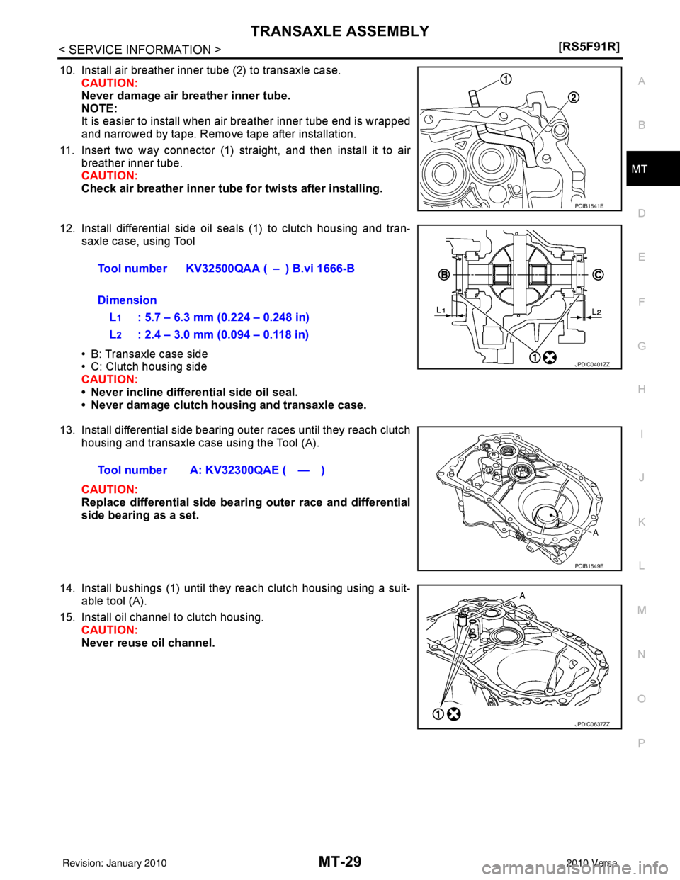
10. Install air breather inner tube (2) to transaxle case. CAUTION:
Never damage air breather inner tube.
NOTE:
It is easier to install when air breather inner tube end is wrapped
and narrowed by tape. Remove tape after installation.
11. Insert two way connector (1) straight, and then install it to air breather inner tube.
CAUTION:
Check air breather inner tube fo r twists after installing.
12. Install differential side oil seals (1) to clutch housing and tran- saxle case, using Tool
• B: Transaxle case side
• C: Clutch housing side
CAUTION:
• Never incline differential side oil seal.
• Never damage clutch housing and transaxle case.
13. Install differential side bearing outer races until they reach clutch housing and transaxle case using the Tool (A).
CAUTION:
Replace differential side bearing outer race and differential
side bearing as a set.
14. Install bushings (1) until they reach clutch housing using a suit- able tool (A).
15. Install oil channel to clutch housing. CAUTION:
Never reuse oil channel.
PCIB1541E
Tool number KV32500QAA ( – ) B.vi 1666-B
Dimension
L
1: 5.7 – 6.3 mm (0.224 – 0.248 in)
L
2: 2.4 – 3.0 mm (0.094 – 0.118 in)
JPDIC0401ZZ
Tool number A: KV32300QAE ( — )
PCIB1549E
JPDIC0637ZZ
Revision: January 20102010 Versa
Page 3225 of 3745
FINAL DRIVEMT-41
< SERVICE INFORMATION > [RS5F91R]
D
E
F
G H
I
J
K L
M A
B
MT
N
O P
FINAL DRIVE
Disassembly and AssemblyINFOID:0000000005397181
DISASSEMBLY
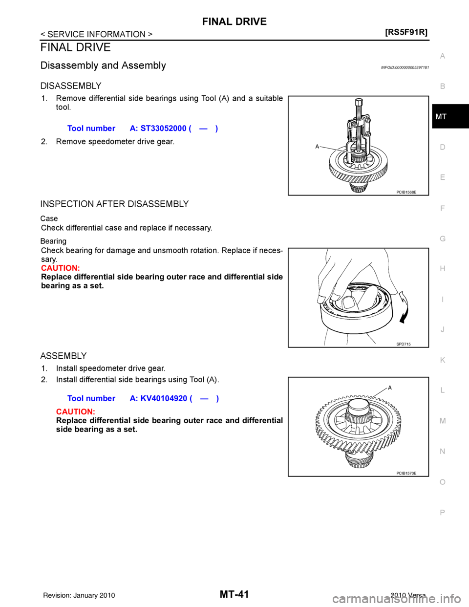
1. Remove differential side bearings using Tool (A) and a suitable tool.
2. Remove speedometer drive gear.
INSPECTION AFTER DISASSEMBLY
Case
Check differential case and replace if necessary.
Bearing
Check bearing for damage and unsmooth rotation. Replace if neces-
sary.
CAUTION:
Replace differential side bearing outer race and differential side
bearing as a set.
ASSEMBLY
1. Install speedometer drive gear.
2. Install differential side bearings using Tool (A). CAUTION:
Replace differential side bearing outer race and differential
side bearing as a set.Tool number A: ST33052000 ( — )
PCIB1568E
SPD715
Tool number A: KV40104920 ( — )
PCIB1570E
Revision: January 20102010 Versa
Page 3230 of 3745
MT-46
< SERVICE INFORMATION >[RS6F94R]
PREPARATION
PREPARATION
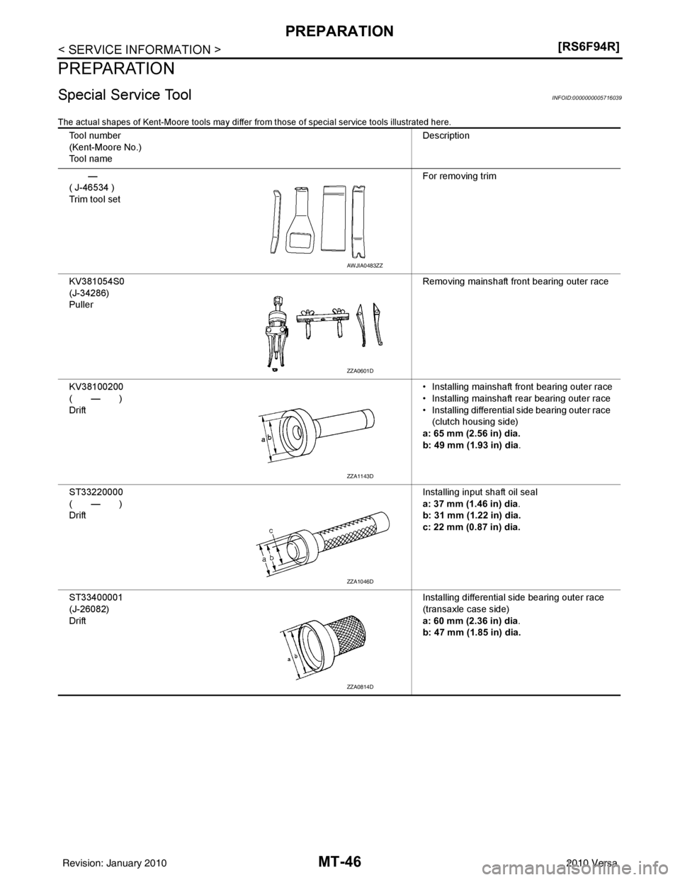
Special Service ToolINFOID:0000000005716039
The actual shapes of Kent-Moore tool
s may differ from those of special service tools illustrated here.
Tool number
(Kent-Moore No.)
Tool name Description
—
( J-46534 )
Trim tool set For removing trim
KV381054S0
(J-34286)
Puller Removing mainshaft front bearing outer race
KV38100200
(—)
Drift • Installing mainshaft front bearing outer race
• Installing mainshaft rear bearing outer race
• Installing differential side bearing outer race
(clutch housing side)
a: 65 mm (2.56 in) dia.
b: 49 mm (1.93 in) dia .
ST33220000
(—)
Drift Installing input shaft oil seal
a: 37 mm (1.46 in) dia
.
b: 31 mm (1.22 in) dia.
c: 22 mm (0.87 in) dia.
ST33400001
(J-26082)
Drift Installing differential side bearing outer race
(transaxle case side)
a: 60 mm (2.36 in) dia
.
b: 47 mm (1.85 in) dia.
AWJIA0483ZZ
ZZA0601D
ZZA1143D
ZZA1046D
ZZA0814D
Revision: January 20102010 Versa
Page 3231 of 3745
PREPARATIONMT-47
< SERVICE INFORMATION > [RS6F94R]
D
E
F
G H
I
J
K L
M A
B
MT
N
O P
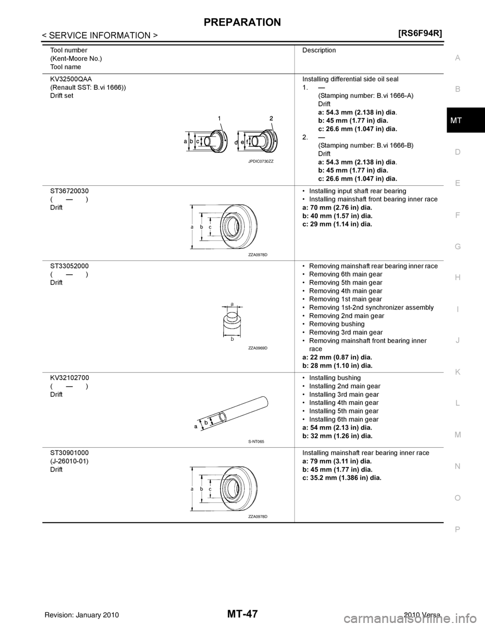
KV32500QAA
(Renault SST: B.vi 1666))
Drift set Installing differential side oil seal
1. —
(Stamping number: B.vi 1666-A)
Drift
a: 54.3 mm (2.138 in) dia.
b: 45 mm (1.77 in) dia.
c: 26.6 mm (1.047 in) dia.
2. — (Stamping number: B.vi 1666-B)
Drift
a: 54.3 mm (2.138 in) dia.
b: 45 mm (1.77 in) dia.
c: 26.6 mm (1.047 in) dia.
ST36720030
(—)
Drift • Installing input shaft rear bearing
• Installing mainshaft front bearing inner race
a: 70 mm (2.76 in) dia.
b: 40 mm (1.57 in) dia.
c: 29 mm (1.14 in) dia.
ST33052000
(—)
Drift • Removing mainshaft rear bearing inner race
• Removing 6th main gear
• Removing 5th main gear
• Removing 4th main gear
• Removing 1st main gear
• Removing 1st-2nd synchronizer assembly
• Removing 2nd main gear
• Removing bushing
• Removing 3rd main gear
• Removing mainshaft front bearing inner
race
a: 22 mm (0.87 in) dia.
b: 28 mm (1.10 in) dia.
KV32102700
(—)
Drift • Installing bushing
• Installing 2nd main gear
• Installing 3rd main gear
• Installing 4th main gear
• Installing 5th main gear
• Installing 6th main gear
a: 54 mm (2.13 in) dia.
b: 32 mm (1.26 in) dia.
ST30901000
(J-26010-01)
Drift Installing mainshaft rear bearing inner race
a: 79 mm (3.11 in) dia.
b: 45 mm (1.77 in) dia.
c: 35.2 mm (1.386 in) dia.
Tool number
(Kent-Moore No.)
Tool name
Description
JPDIC0730ZZ
ZZA0978D
ZZA0969D
S-NT065
ZZA0978D
Revision: January 20102010 Versa