belt NISSAN TIIDA 2010 Service Manual PDF
[x] Cancel search | Manufacturer: NISSAN, Model Year: 2010, Model line: TIIDA, Model: NISSAN TIIDA 2010Pages: 3745, PDF Size: 73.67 MB
Page 2346 of 3745

REAR PARCEL SHELF FINISHEREI-45
< ON-VEHICLE REPAIR >
C
DE
F
G H
J
K L
M A
B
EI
N
O P
REAR PARCEL SHELF FINISHER
Removal and InstallationINFOID:0000000005396841
REMOVAL
1. Remove rear seat. Refer to SE-16, "Removal and Installation".
2. Remove rear pillar finisher. Refer to EI-40, "
Removal and Installation".
3. Remove high mounted stop lamp and disconnect connector (if equipped).
4. Remove rear parcel shelf finisher.
INSTALLATION
Installation is in the reverse order of removal.
LIIA2923E
1. Rear seat belt shoulder anchor cover 2. Child anchor cover 3. Child anchor cover base
4. High mounted stop lamp (if equipped) 5. Rear parcel shelf finisher Pawl
Vehicle front
Revision: January 20102010 Versa
Page 2351 of 3745
EI-50
< ON-VEHICLE REPAIR >
HEADLINING
Removal and Installation - Hatchback
INFOID:0000000005396844
REMOVAL
1. Disconnect the negative and positive battery termi nals, then wait at least three minutes.
2. Remove front seat assembly RH/LH. Refer to SE-12, "
Removal and Installation".
3. Remove rear seat cushion and rear seatback. Refer to SE-16, "
Removal and Installation".
4. Remove front seat belt shoulder anchor RH/LH. Refer to SB-4, "
Removal and Installation of Front Seat
Belt".
5. Remove center console body assembly. Refer to IP-11
.
6. Remove front pillar garnish RH/LH. Refer to EI-40, "
Removal and Installation".
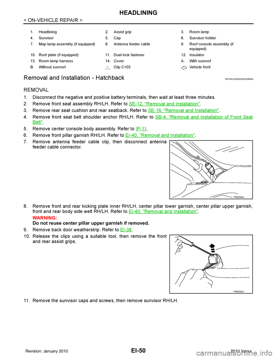
7. Remove antenna feeder cable clip, then disconnect antenna feeder cable connector.
8. Remove front and rear kicking plate inner RH/LH, center pillar lower garnish, center pillar upper garnish, front and rear body side welt RH/LH. Refer to EI-40, "
Removal and Installation".
WARNING:
Do not reuse center pillar upper garnish if removed.
9. Remove back door weatherstrip. Refer to EI-38
.
10. Release the clips using a suitable tool, then remove the front and rear assist grips.
11. Remove the sunvisor caps and screws, then remove sunvisor RH/LH.
1. Headlining 2. Assist grip 3. Room lamp
4. Sunvisor 5. Cap 6. Sunvisor holder
7. Map lamp assembly (if equipped) 8. Antenna feeder cable 9. Roof console assembly (if
equipped)
10. Roof plate (if equipped) 11. Dual lock fastener 12. Insulator
13. Room lamp harness 14. Cover A. With sunroof
B. Without sunroof Clip C103Vehicle front
PIIB2583J
PIIB2584J
Revision: January 20102010 Versa
Page 2353 of 3745
EI-52
< ON-VEHICLE REPAIR >
HEADLINING
Avoid headlining damage when installing by inserting rear clips first during assembly.
Removal and Installation - SedanINFOID:0000000005396845
REMOVAL
1. Disconnect the negative and positive battery terminals, then wait at least three minutes.
2. Remove front seat assembly RH/LH. Refer to SE-12, "
Removal and Installation".
3. Remove rear seat cushion and rear seatback. Refer to SE-16, "
Removal and Installation".
4. Remove front seat belt shoulder anchor RH/LH. Refer to SB-4, "
Removal and Installation of Front Seat
Belt".
5. Remove center console body assembly. Refer to IP-11
.
6. Remove front pillar garnish RH/LH. Refer to EI-40, "
Removal and Installation".
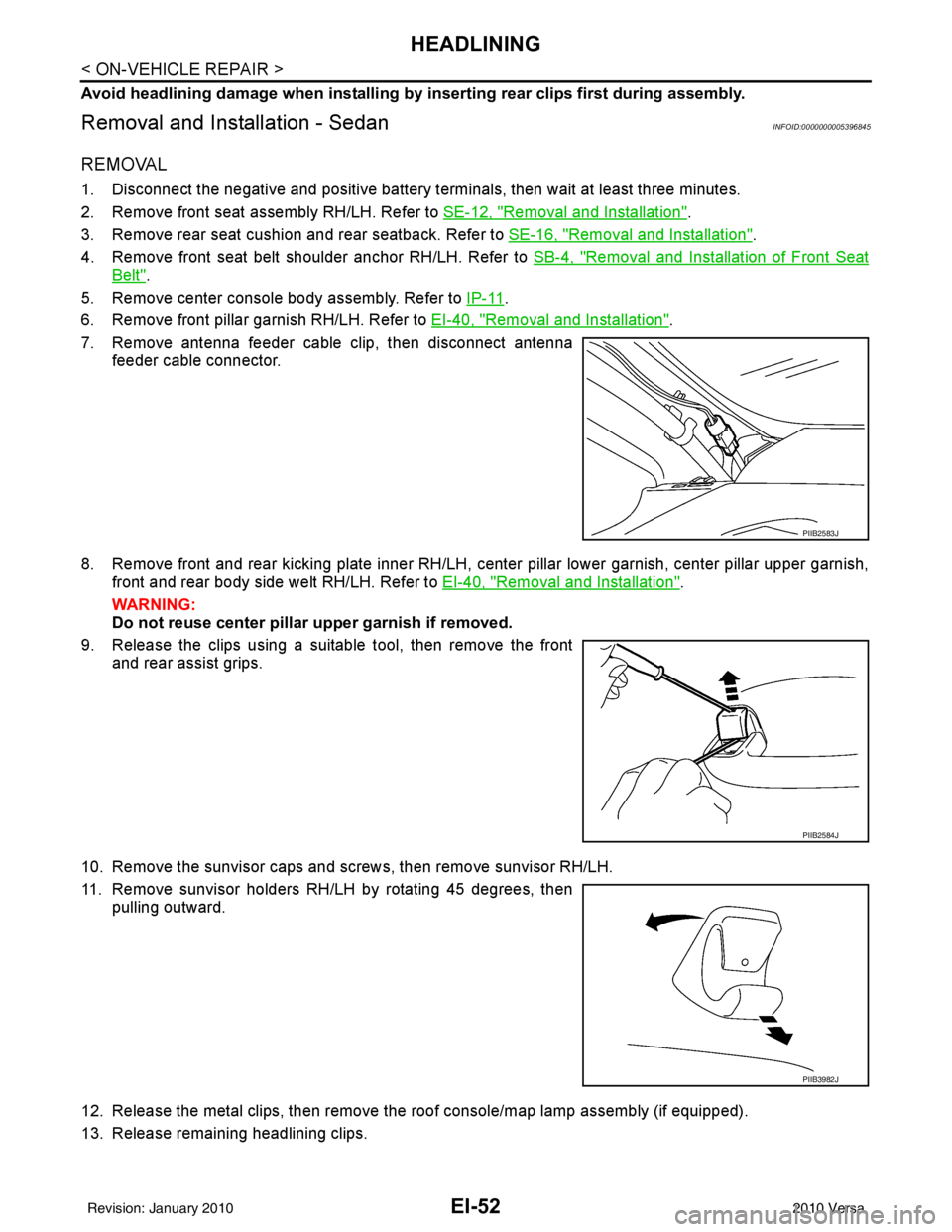
7. Remove antenna feeder cable clip, then disconnect antenna feeder cable connector.
8. Remove front and rear kicking plate inner RH/LH, center pillar lower garnish, center pillar upper garnish, front and rear body side welt RH/LH. Refer to EI-40, "
Removal and Installation".
WARNING:
Do not reuse center pillar upper garnish if removed.
9. Release the clips using a suitable tool, then remove the front and rear assist grips.
10. Remove the sunvisor caps and scr ews, then remove sunvisor RH/LH.
11. Remove sunvisor holders RH/LH by rotating 45 degrees, then pulling outward.
12. Release the metal clips, then remove the roof console/map lamp assembly (if equipped).
13. Release remaining headlining clips.
PIIB2583J
PIIB2584J
PIIB3982J
Revision: January 20102010 Versa
Page 2360 of 3745
EM-1
ENGINE
C
DE
F
G H
I
J
K L
M
SECTION EM
A
EM
N
O P
CONTENTS
ENGINE MECHANICAL
HR16DE
PRECAUTION ....... ........................................
4
PRECAUTIONS .............................................. .....4
Precaution for Supplemental Restraint System
(SRS) "AIR BAG" and "SEAT BELT PRE-TEN-
SIONER" ............................................................. ......
4
Precaution Necessary for Steering Wheel Rota-
tion After Battery Disconnect ............................... ......
4
Precaution for Procedure without Cowl Top Cover ......5
Precaution for Drain Coolant .....................................5
Precaution for Disconnecting Fuel Piping ........... ......5
Precaution for Removal and Disassembly ................5
Precaution for Inspection, Repair and Replace-
ment .................................................................... ......
5
Precaution for Assembly and Installation ..................5
Parts Requiring Angular Tightening ..........................6
Precaution for Liquid Gasket ............................... ......6
PREPARATION ............................................8
PREPARATION .............................................. .....8
Special Service Tools .......................................... ......8
Commercial Service Tools ........................................9
SYMPTOM DIAGNOSIS ..............................12
NOISE, VIBRATION AND HARSHNESS
(NVH) TROUBLESHOOTING ........................ ....
12
NVH Troubleshooting - Engine Noise ................. ....12
Use the Chart Below to Help You Find the Cause
of the Symptom .......................................................
13
ON-VEHICLE MAINTENANCE ....................14
DRIVE BELTS ................................................ ....14
Checking ............................................................. ....14
Tension Adjustment ................................................14
Removal and Installation .........................................15
AIR CLEANER FILTER .................................. ....17
Removal and Installation ..................................... ....17
SPARK PLUG ...................................................18
Exploded View .........................................................18
Removal and Installation .........................................18
CAMSHAFT VALVE CLEARANCE ..................20
Inspection and Adjustment ......................................20
COMPRESSION PRESSURE ...........................23
Inspection ................................................................23
ON-VEHICLE REPAIR .................................24
DRIVE BELT IDLER PULLEY ..........................24
Exploded View ..................................................... ....24
Removal and Installation .........................................24
AIR CLEANER AND AIR DUCT .......................26
Exploded View .........................................................26
Removal and Installation .........................................26
Inspection ................................................................27
INTAKE MANIFOLD .........................................28
Exploded View .........................................................28
Removal and Installation .........................................28
EXHAUST MANIFOLD ......................................31
Exploded View .........................................................31
Removal and Installation .........................................31
FUEL INJECTOR AND FUEL TUBE ................34
Exploded View .........................................................34
Removal and Installation .........................................34
Inspection ................................................................38
OIL PAN (LOWER) ...........................................39
Exploded View .........................................................39
Removal and Installation .........................................39
Inspection ................................................................41
OIL PAN (UPPER) AND OIL STRAINER .........42
Component ..............................................................42
Revision: January 20102010 Versa
Page 2361 of 3745
EM-2
Removal and Installation ........................................42
IGNITION COIL, SPARK PLUG AND ROCK-
ER COVER .........................................................
46
Exploded View ........................................................46
Removal and Installation ........................................46
TIMING CHAIN ............................................... ...49
Exploded View ..................................................... ...49
Removal and Installation ........................................49
Inspection ...............................................................57
CAMSHAFT .......................................................59
Exploded View ..................................................... ...59
Removal and Installation ........................................59
Inspection ...............................................................65
OIL SEAL ...........................................................70
VALVE OIL SEAL .................................................. ...70
VALVE OIL SEAL : Removal and Installation .........70
FRONT OIL SEAL .................................................. ...70
FRONT OIL SEAL : Removal and Installation ........71
REAR OIL SEAL .................................................... ...71
REAR OIL SEAL : Removal and Installation ..........71
CYLINDER HEAD ........................................... ...73
Removal and Installation ..................................... ...73
Disassembly and Assembly ....................................76
REMOVAL AND INSTALLATION ...............82
ENGINE ASSEMBLY ...................................... ...82
Exploded View ..................................................... ...82
Removal and Installation ........................................82
Inspection ...............................................................85
DISASSEMBLY AND ASSEMBLY .............87
ENGINE STAND SETTING ............................. ...87
Setting ................................................................. ...87
ENGINE UNIT ....................................................88
Disassembly ........................................................ ...88
Assembly ................................................................88
CYLINDER BLOCK ...........................................89
Exploded View ..................................................... ...89
Disassembly and Assembly ....................................90
Inspection ...............................................................97
HOW TO SELECT PISTON AND BEARING ...106
Description ........................................................... ..106
Connecting Rod Bearing .......................................106
Main Bearing .........................................................108
SERVICE DATA AND SPECIFICATIONS
(SDS) ........................................................ ..
111
SERVICE DATA AND SPECIFICATIONS
(SDS) ............................................................... .
111
General Specification ........................................... .111
Drive Belts .............................................................111
Spark Plug ............................................................112
Exhaust Manifold ..................................................112
Camshaft ...............................................................112
Cylinder Head .......................................................114
Cylinder Block .......................................................116
Connecting Rod Bearing .......................................119
Main Bearing .........................................................120
MR18DE
SERVICE INFORMATION .. .......................
122
PRECAUTIONS .............................................. ..122
Precaution for Supplemental Restraint System
(SRS) "AIR BAG" and "SEAT BELT PRE-TEN-
SIONER" .............................................................. .
122
Precaution Necessary for Steering Wheel Rota-
tion After Battery Disconnect ................................
122
Precaution for Procedure without Cowl Top Cover .123
Precaution for Drain Coolant .................................123
Precaution for Disconnecting Fuel Piping ............ .123
Precaution for Removal and Disassembly ............123
Precaution for Inspection, Repair and Replace-
ment ......................................................................
123
Precaution for Assembly and Installation ............. .123
Parts Requiring Angular Tightening ......................124
Precaution for Liquid Gasket .................................124
PREPARATION ................................................126
Special Service Tool ............................................ .126
Commercial Service Tool ......................................128
NOISE, VIBRATION AND HARSHNESS
(NVH) TROUBLESHOOTING ...........................
130
NVH Troubleshooting - Engine Noise .................. .130
Use the Chart Below to Help You Find the Cause
of the Symptom .................................................... .
131
DRIVE BELTS ..................................................132
Component .......................................................... .132
Checking Drive Belts .............................................132
Tension Adjustment ..............................................132
Removal and Installation .......................................132
Component .......................................................... .133
Removal and Installation of Drive Belt Auto Ten-
sioner ....................................................................
133
AIR CLEANER AND AIR DUCT .......................135
Component .......................................................... .135
Removal and Installation .......................................135
Changing Air Cleaner Filter ...................................136
INTAKE MANIFOLD ....................................... ..137
Component .......................................................... .137
Removal and Installation .......................................137
EXHAUST MANIFOLD ................................... ..140
Component .......................................................... .140
Removal and Installation .......................................140
Revision: January 20102010 Versa
Page 2363 of 3745

EM-4
< PRECAUTION >[HR16DE]
PRECAUTIONS
PRECAUTION
PRECAUTIONS
Precaution for Supplemental Restraint Syst
em (SRS) "AIR BAG" and "SEAT BELT
PRE-TENSIONER"
INFOID:0000000005398023
The Supplemental Restraint System such as “A IR BAG” and “SEAT BELT PRE-TENSIONER”, used along
with a front seat belt, helps to reduce the risk or severity of injury to the driver and front passenger for certain
types of collision. This system includes seat belt switch inputs and dual stage front air bag modules. The SRS
system uses the seat belt switches to determine the front air bag deployment, and may only deploy one front
air bag, depending on the severity of a collision and w hether the front occupants are belted or unbelted.
Information necessary to service the system safely is included in the SRS and SB section of this Service Man-
ual.
WARNING:
• To avoid rendering the SRS inopera tive, which could increase the risk of personal injury or death in
the event of a collision which would result in air bag inflation, all maintenance must be performed by
an authorized NISSAN/INFINITI dealer.
• Improper maintenance, including incorrect removal and installation of the SRS can lead to personal
injury caused by unintent ional activation of the system. For re moval of Spiral Cable and Air Bag
Module, see the SRS section.
• Do not use electrical test equipmen t on any circuit related to the SRS unless instructed to in this
Service Manual. SRS wiring harn esses can be identified by yellow and/or orange harnesses or har-
ness connectors.
PRECAUTIONS WHEN USING POWER TOOLS (AIR OR ELECTRIC) AND HAMMERS
WARNING:
• When working near the Airbag Diagnosis Sensor Unit or other Airbag System sensors with the Igni-
tion ON or engine running, DO NOT use air or electri c power tools or strike near the sensor(s) with a
hammer. Heavy vibration could activate the sensor( s) and deploy the air bag(s), possibly causing
serious injury.
• When using air or electric power tools or hammers , always switch the Ignition OFF, disconnect the
battery, and wait at least 3 minu tes before performing any service.
Precaution Necessary for Steering W heel Rotation After Battery Disconnect
INFOID:0000000005398024
NOTE:
• This Procedure is applied only to models with Intelligent Key system and NATS (NISSAN ANTI-THEFT SYS-
TEM).
• Remove and install all control units after disconnecting both battery cables with the ignition knob in the
″LOCK ″ position.
• Always use CONSULT-III to perform self-diagnosis as a part of each function inspection after finishing work.
If DTC is detected, perform trouble diagnosis according to self-diagnostic results.
For models equipped with the Intelligent Key system and NATS, an electrically controlled steering lock mech-
anism is adopted on the key cylinder.
For this reason, if the battery is disconnected or if the battery is discharged, the steering wheel will lock and
steering wheel rotation will become impossible.
If steering wheel rotation is required when battery pow er is interrupted, follow the procedure below before
starting the repair operation.
OPERATION PROCEDURE
1. Connect both battery cables. NOTE:
Supply power using jumper cables if battery is discharged.
2. Use the Intelligent Key or mechanical key to turn the ignition switch to the ″ACC ″ position. At this time, the
steering lock will be released.
3. Disconnect both battery cables. The steering lock will remain released and the steering wheel can be rotated.
4. Perform the necessary repair operation.
Revision: January 20102010 Versa
Page 2370 of 3745

PREPARATIONEM-11
< PREPARATION > [HR16DE]
C
D
E
F
G H
I
J
K L
M A
EM
NP
O
Acoustic tension gauge
Checking drive belt tension
Anti-seize lubricant (Permatex 133AR
or equivalent meeting MIL specifica-
tion MIL-A-907) Lubricating oxygen sensor thread cleaning
tool when reconditioning exhaust system
threads
Manual lift table caddy Removing and installing engine
Tool name
Description
PBIC3881E
AEM489
ZZA1210D
Revision: January 20102010 Versa
Page 2372 of 3745

NOISE, VIBRATION AND HARSHNESS (NVH) TROUBLESHOOTINGEM-13
< SYMPTOM DIAGNOSIS > [HR16DE]
C
D
E
F
G H
I
J
K L
M A
EM
NP
O
Use the Chart Below to Help You
Find the Cause of the SymptomINFOID:0000000005398036
1. Locate the area where noise occurs.
2. Confirm the type of noise.
3. Specify the operating condition of engine.
4. Check specified noise source.
If necessary, repair or replace these parts.
A: Closely related B: Related C: Sometimes related —: Not relatedLocation
of noise Type of
noise Operating condition of engine
Source of noise Check item Refer-
ence page
Before
warm- up After
warm- up When
start- ing When
idling When
racing While
driving
Top of en-
gine
Rocker
cover
Cylinder
head Ticking or
clicking
CA—AB— Tappet
noiseValve clearance
EM-20
Rattle C A — A B C Camshaft
bearing
noiseCamshaft journal oil
clearance
Camshaft runout
EM-112EM-112
Crank-
shaft pul-
ley
Cylinder
block
(Side of
engine)
Oil panSlap or
knock
—A—BB—
Piston pin
noisePiston to piston pin oil
clearance
Connecting rod small
end clearance
EM-116
EM-119
Slap or
rap
A——BBA
Piston
slap noisePiston to cylinder bore
clearance
Piston ring side clear-
ance
Piston ring end gap
Connecting rod bend
and torsion EM-116EM-116
EM-116
EM-119
Knock A B C B B B
Connect-
ing rod
bearing
noiseConnecting rod small
end clearance
Connecting rod bearing
oil clearance
EM-116EM-119
Knock A B — A B C
Main bear-
ing noiseMain bearing oil clear-
ance
Crankshaft runout EM-120EM-116
Front of
engine
Front cov-
erTapping or
ticking
AA—BBB Timing
chain and
chain ten-
sioner
noiseTiming chain cracks
and wear
Timing chain tensioner
operation
EM-57
Front of
engineSqueak-
ing or fizz-
ing
AB—B—C Drive belt
(Sticking
or slip-
ping)Drive belt deflection
E M - 111
CreakingA B ABAB Drive belt
(Slipping)Idler pulley bearing op-
eration
Squall
Creak AB—BAB Water
pump
noise
Water pump operation
CO-22
Revision: January 20102010 Versa
Page 2373 of 3745

EM-14
< ON-VEHICLE MAINTENANCE >[HR16DE]
DRIVE BELTS
ON-VEHICLE MAINTENANCE
DRIVE BELTS
CheckingINFOID:0000000005398037
• Inspection should be done only when engine is cold or over 30
minutes after the engine is stopped.
• Visually check belts for wear, damage, and cracks on inside and edges.
• Turn crankshaft pulley two times clockwise, and make sure tension on all pulleys is equal before doing the test.
• When measuring deflection, apply 98 N (10 kg, 22 lb) at the ( ) marked point.
• Measure the belt tension and frequency with acous tic tension gauge at the ( ) marked point.
CAUTION:
• When the tension and frequency are measured, the acoustic tension gauge should be used.
• When checking immediately after installation, first ad just it to the specified value. Then, after turning
crankshaft two turns or more, re-adjust to the specified value to avoid variation in deflection
between pulleys.
Tension AdjustmentINFOID:0000000005398038
CAUTION:
• When belt is replaced with new one, adjust belt tension to the value for “New belt”, because new belt will not fully seat in the pulley groove.
• When tension of the belt being used exceeds “Limit”, adjust it to the value for “After adjusted”.
• When installing a belt, make sure it is correctly engaged with the pulley groove.
• Never allow oil or engine coolant to get on the belt.
• Never twist or bend the belt strongly.
1. Loosen the idler pulley lock nut (A) from the tightening position with the specified torque by 45 degrees.
CAUTION:
1 : Generator
2: Water pump
3 : Crankshaft pulley
4: A/C compressor (with A/C models)
: Idler pulley (without A/C models)
5 : Idler pulley
6: Drive belt
Belt Deflection / Belt Tension and Frequency : Refer to EM-111, "Drive Belts".
PBIC3642E
LocationLocation of adjuster and tightening method
Drive belt Adjusting bolt on idler pulley
1 : Generator
2: Water pump
3 : Crankshaft pulley
4 : A/C compressor
(with A/C models)
: Idler pulley (without A/C models)
5 : Idler pulley
6 : Drive belt
A : Idler pulley lock nut
B : Adjusting bolt
PBIC3643E
Revision: January 20102010 Versa
Page 2374 of 3745

DRIVE BELTSEM-15
< ON-VEHICLE MAINTENANCE > [HR16DE]
C
D
E
F
G H
I
J
K L
M A
EM
NP
O
• When the lock nut is loosened excessively, the idle
r pulley tilts and the correct tension adjust-
ment cannot be performed. Never loo sen it excessively (more than 45 degrees).
• Put a matching mark on the lock nut, and check turning angle with a protractor. Never visually
check the tightening angle.
2. Adjust the belt tension by turning the adjusting bolt. CAUTION:
• When checking immediately after in stallation, first adjust it to the specified value. Then, after
turning crankshaft two turns or more, re-adjust to the specified value to avoid variation in deflec-
tion between pulleys.
• When the tension adjustment is performed, the lo ck nut should be in the condition at step“2”. If
the tension adjustment is performed when the lo ck nut is loosened more than the standard, the
idler pulley tilts and the correct tens ion adjustment cannot be performed.
3. Tighten the idler pulley lock nut.
Removal and InstallationINFOID:0000000005398039
REMOVAL
1. Loosen the idler pulley lock nut (A), and then adjust the belt ten- sion by turning the adjusting bolt (B).
2. Remove drive belt.
INSTALLATION
1. Pull the idler pulley in the loosening direction, and then tempo- rarily tighten the idler pulley lock nut (A) to the following torque.
NOTE:
Do not move the lock nut from the tightened position. Proceed to step “2”.
2. Install the drive belt to each pulley. CAUTION:
• Make sure that there is no oil, grease, or coolant, etc. in pulley grooves.
• Make sure that the belt is securely inside the groove on each pulley.
3. Adjust drive belt tension by turning the adjusting bolt. Refer to EM-14, "
Tension Adjustment".
CAUTION: Idler pulley lock nut : 34.8 N·m (3.5 kg-m, 26 ft-lb)
1 : Generator
2: Water pump
3 : Crankshaft pulley
4
: A/C compressor (with A/C models)
: Idler pulley (without A/C models)
5 : Idler pulley
6: Drive belt
PBIC3643E
1 : Generator
2: Water pump
3 : Crankshaft pulley
4 : A/C compressor (with A/C models)
: Idler pulley (without A/C models)
5 : Idler pulley
6: Drive belt
B : Adjusting bolt
Idler pulley lock nut : 4.4 N·m (0.45 kg-m, 39 in-lb)
(temporary tightening)
PBIC3643E
Revision: January 20102010 Versa