belt NISSAN TIIDA 2010 Service Manual PDF
[x] Cancel search | Manufacturer: NISSAN, Model Year: 2010, Model line: TIIDA, Model: NISSAN TIIDA 2010Pages: 3745, PDF Size: 73.67 MB
Page 2375 of 3745
EM-16
< ON-VEHICLE MAINTENANCE >[HR16DE]
DRIVE BELTS
• Perform the belt tension adjustment with the lock
nut temporarily tightened at the step “1” so as
not to tilt the idler pulley.
• When checking immediately after in stallation, first adjust it to the specified value. Then, after
turning crankshaft two turns or more, re-adjust to the specified value to avoid variation in deflec-
tion between pulleys.
4. Tighten the idler pulley lock nut.
5. Make sure that belt tension of each belt is within the standard. Idler pulley lock nut : 34.8 N·m (3.5 kg-m, 26 ft-lb)
Revision: January 20102010 Versa
Page 2383 of 3745
EM-24
< ON-VEHICLE REPAIR >[HR16DE]
DRIVE BELT IDLER PULLEY
ON-VEHICLE REPAIR
DRIVE BELT IDLER PULLEY
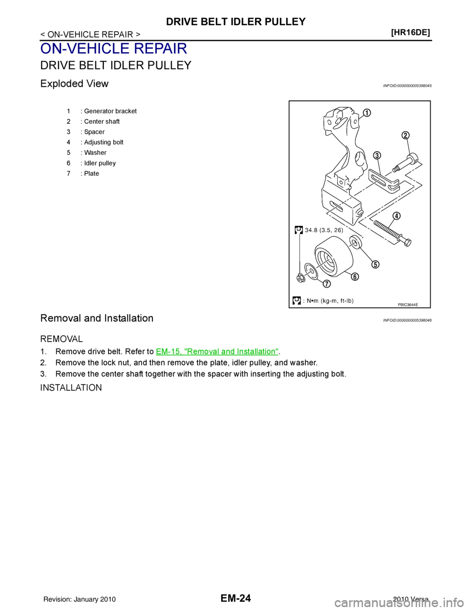
Exploded ViewINFOID:0000000005398045
Removal and InstallationINFOID:0000000005398046
REMOVAL
1. Remove drive belt. Refer to
EM-15, "Removal and Installation".
2. Remove the lock nut, and then remove the plate, idler pulley, and washer.
3. Remove the center shaft together with the spacer with inserting the adjusting bolt.
INSTALLATION
1 : Generator bracket
2 : Center shaft
3 : Spacer
4 : Adjusting bolt
5: Washer
6 : Idler pulley
7: Plate
PBIC3644E
Revision: January 20102010 Versa
Page 2384 of 3745
DRIVE BELT IDLER PULLEYEM-25
< ON-VEHICLE REPAIR > [HR16DE]
C
D
E
F
G H
I
J
K L
M A
EM
NP
O
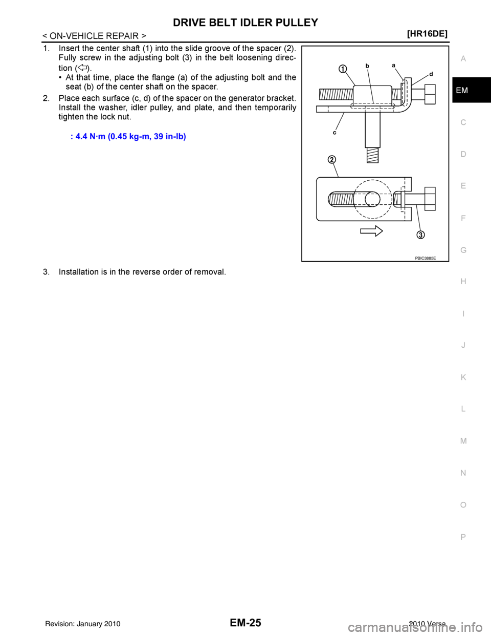
1. Insert the center shaft (1) into the slide groove of the spacer (2).
Fully screw in the adjusting bolt (3) in the belt loosening direc-
tion ( ).
• At that time, place the flange (a) of the adjusting bolt and theseat (b) of the center shaft on the spacer.
2. Place each surface (c, d) of the spacer on the generator bracket. Install the washer, idler pulley, and plate, and then temporarily
tighten the lock nut.
3. Installation is in the reverse order of removal. : 4.4 N·m (0.45 kg-m, 39 in-lb)
PBIC3885E
Revision: January 20102010 Versa
Page 2409 of 3745
EM-50
< ON-VEHICLE REPAIR >[HR16DE]
TIMING CHAIN
4. Remove the following parts.
• Intake manifold: Refer to EM-28, "
Exploded View".
• Drive belt: Refer to EM-15, "
Removal and Installation".
• Water pump pulley: Refer to CO-21, "
Exploded View".
• Ground cable (RH)
5. Support the bottom surface of engine using a tr ansmission jack, and then remove the engine mounting
bracket and insulator (RH). Refer to EM-82, "
Exploded View".
6. Remove rocker cover. Refer to EM-46, "
Exploded View".
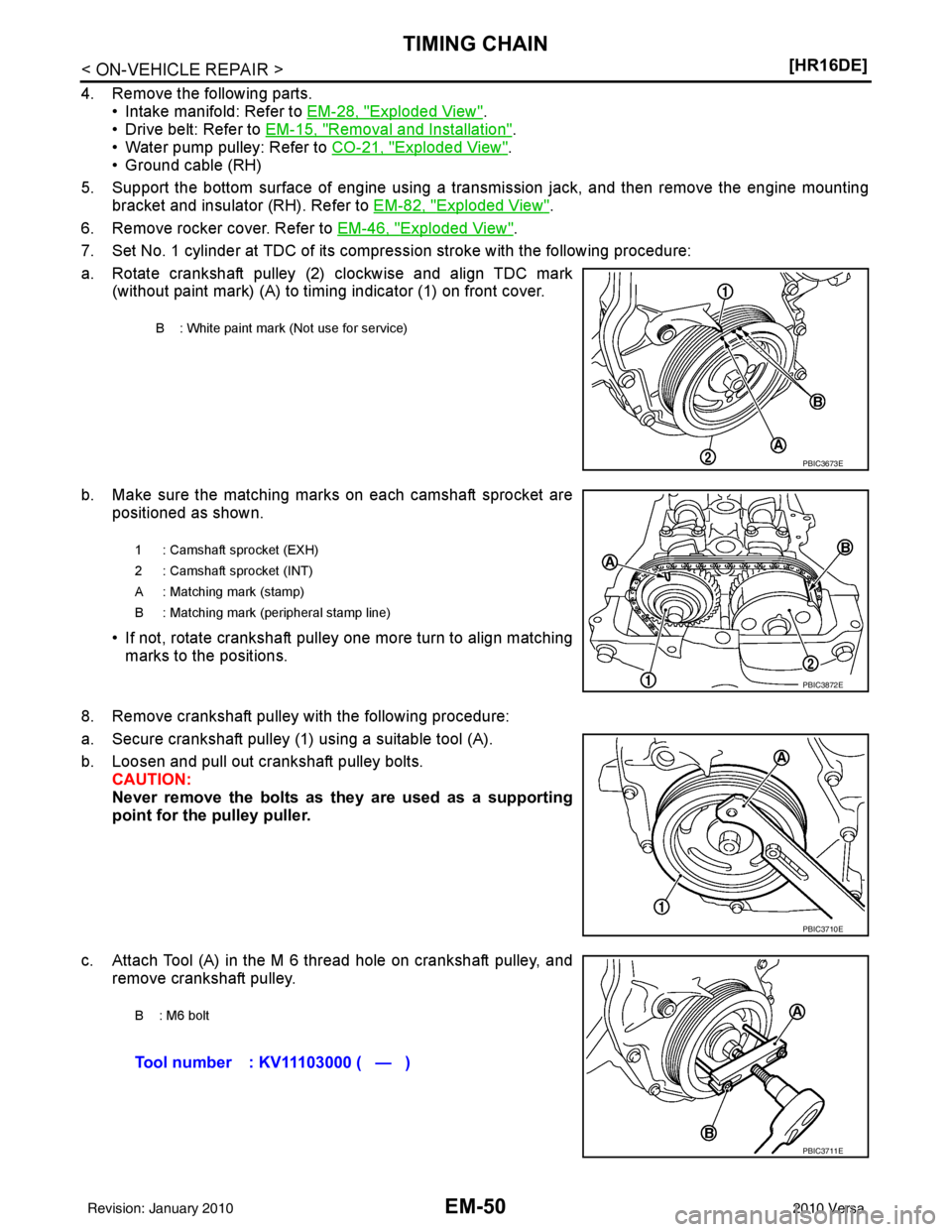
7. Set No. 1 cylinder at TDC of its compression stroke with the following procedure:
a. Rotate crankshaft pulley (2) clockwise and align TDC mark (without paint mark) (A) to timing indicator (1) on front cover.
b. Make sure the matching marks on each camshaft sprocket are positioned as shown.
• If not, rotate crankshaft pulley one more turn to align matching
marks to the positions.
8. Remove crankshaft pulley with the following procedure:
a. Secure crankshaft pulley (1) using a suitable tool (A).
b. Loosen and pull out crankshaft pulley bolts. CAUTION:
Never remove the bolts as they are used as a supporting
point for the pulley puller.
c. Attach Tool (A) in the M 6 thread hole on crankshaft pulley, and remove crankshaft pulley.
B : White paint mark (Not use for service)
PBIC3673E
1 : Camshaft sprocket (EXH)
2 : Camshaft sprocket (INT)
A : Matching mark (stamp)
B : Matching mark (peripheral stamp line)
PBIC3872E
PBIC3710E
B: M6 bolt
Tool number : KV11103000 ( — )
PBIC3711E
Revision: January 20102010 Versa
Page 2428 of 3745
CAMSHAFTEM-69
< ON-VEHICLE REPAIR > [HR16DE]
C
D
E
F
G H
I
J
K L
M A
EM
NP
O
b. Remove intake manifold. Refer to EM-28, "Exploded View".
c. Disconnect ignition coil and inject or harness connectors. Refer to EM-46, "
Exploded View".
3. Remove intake valve timing control solenoid valve. Refer to EM-49, "
Exploded View".
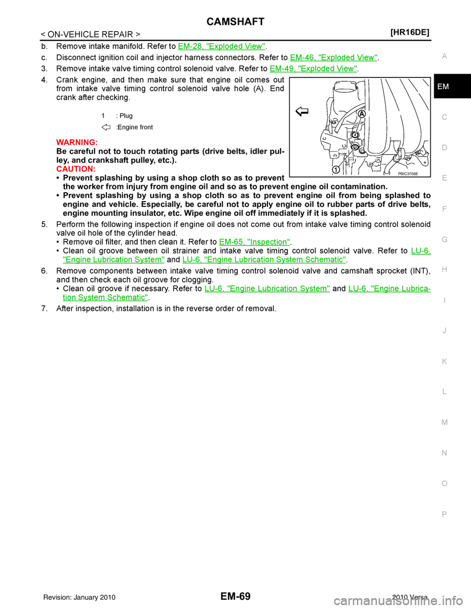
4. Crank engine, and then make sure that engine oil comes out from intake valve timing control solenoid valve hole (A). End
crank after checking.
WARNING:
Be careful not to touch rotating parts (drive belts, idler pul-
ley, and crankshaft pulley, etc.).
CAUTION:
• Prevent splashing by using a shop cloth so as to prevent the worker from injury from engine oil an d so as to prevent engine oil contamination.
• Prevent splashing by using a shop cloth so as to prevent engine oil from being splashed to
engine and vehicle. Especially, be careful not to apply engine oil to rubber parts of drive belts,
engine mounting insulator, etc. Wipe engine oil off immediately if it is splashed.
5. Perform the following inspection if engine oil does not come out from intake valve timing control solenoid
valve oil hole of the cylinder head.
• Remove oil filter, and then clean it. Refer to EM-65, "
Inspection".
• Clean oil groove between oil strainer and intake valve timing control solenoid valve. Refer to LU-6,
"Engine Lubrication System" and LU-6, "Engine Lubrication System Schematic".
6. Remove components between intake valve timing control solenoid valve and camshaft sprocket (INT), and then check each oil groove for clogging.
• Clean oil groove if necessary. Refer to LU-6, "
Engine Lubrication System" and LU-6, "Engine Lubrica-
tion System Schematic".
7. After inspection, installation is in the reverse order of removal.
1: Plug
:Engine front
PBIC3706E
Revision: January 20102010 Versa
Page 2430 of 3745
OIL SEALEM-71
< ON-VEHICLE REPAIR > [HR16DE]
C
D
E
F
G H
I
J
K L
M A
EM
NP
O
FRONT OIL SEAL : Removal and InstallationINFOID:0000000005398071
REMOVAL
1. Remove the following parts:
• Front wheel and tire (RH). Refer to WT-7, "
Adjustment".
• Front fender protector (RH): Refer to EI-24, "
Removal and Installation".
• Drive belt: Refer to EM-15, "
Removal and Installation".
• Crankshaft pulley: Refer to EM-49, "
Exploded View".
2. Remove front oil seal using a suitable tool. CAUTION:
Be careful not to damage fron t timing chain case and crankshaft.
INSTALLATION
1. Apply new engine oil to both oil seal lip and dust seal lip of new front oil seal.
2. Install front oil seal.
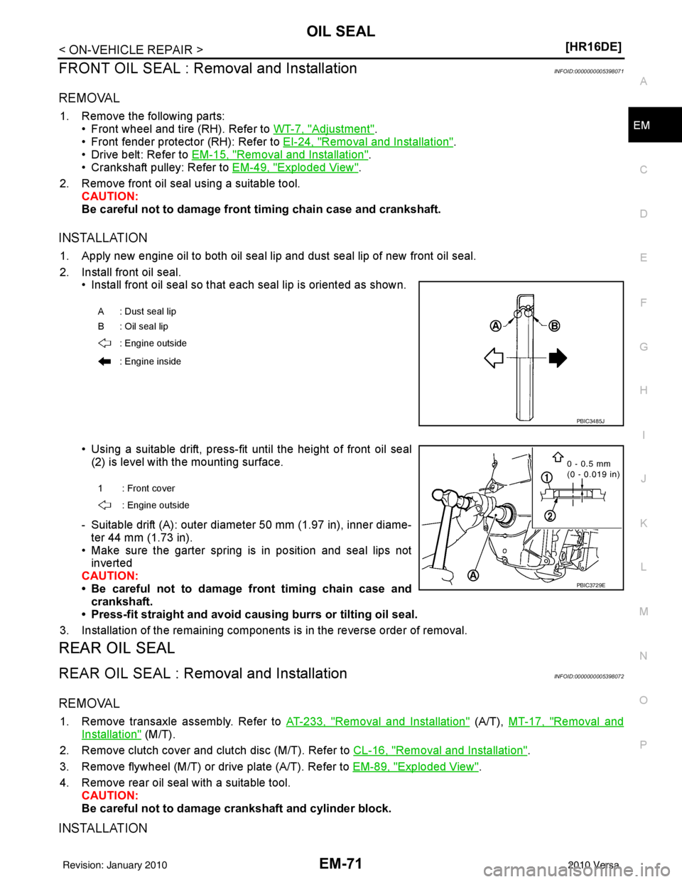
• Install front oil seal so that each seal lip is oriented as shown.
• Using a suitable drift, press-fit until the height of front oil seal
(2) is level with the mounting surface.
- Suitable drift (A): outer diameter 50 mm (1.97 in), inner diame- ter 44 mm (1.73 in).
• Make sure the garter spring is in position and seal lips not inverted
CAUTION:
• Be careful not to damage front timing chain case and
crankshaft.
• Press-fit straight and avoid cau sing burrs or tilting oil seal.
3. Installation of the remaining components is in the reverse order of removal.
REAR OIL SEAL
REAR OIL SEAL : Removal and InstallationINFOID:0000000005398072
REMOVAL
1. Remove transaxle assembly. Refer to AT-233, "Removal and Installation" (A/T), MT-17, "Removal and
Installation" (M/T).
2. Remove clutch cover and clutch disc (M/T). Refer to CL-16, "
Removal and Installation".
3. Remove flywheel (M/T) or drive plate (A/T). Refer to EM-89, "
Exploded View".
4. Remove rear oil seal with a suitable tool. CAUTION:
Be careful not to damage crankshaft and cylinder block.
INSTALLATION
A : Dust seal lip
B : Oil seal lip
: Engine outside
: Engine inside
PBIC3485J
1: Front cover : Engine outside
PBIC3729E
Revision: January 20102010 Versa
Page 2432 of 3745
CYLINDER HEADEM-73
< ON-VEHICLE REPAIR > [HR16DE]
C
D
E
F
G H
I
J
K L
M A
EM
NP
O
CYLINDER HEAD
Removal and InstallationINFOID:0000000005398073
REMOVAL
WARNING:
• Put a “CAUTION: FLAMMABLE” sign in the workshop.
• Be sure to work in a well ventila
ted area and furnish workshop with a CO
2 fire extinguisher.
• Do not smoke while servicing fuel system. Keep open flames and sparks away from the work area.
1. Release fuel pressure. Refer to EC-496, "
Inspection".
2. Drain engine coolant and engine oil. Refer to CO-12, "
Changing Engine Coolant" and LU-8, "Draining".
CAUTION:
• Perform this step when the engine is cold.
• Never spill engine coolant and engine oil on drive belt.
3. Remove the following components and related parts. • Front fender protector (RH). Refer to EI-24, "
Removal and Installation".
• Generator. Refer to SC-25, "
Removal and Installation".
• Exhaust front tube. Refer to EX-6, "
Component".
• Exhaust manifold. Refer to EM-31, "
Exploded View".
• Intake manifold. Refer to EM-28, "
Exploded View".
• Fuel tube and fuel injector. Refer to EM-34, "
Exploded View".
• Water outlet. Refer to CO-25, "
Removal and Installation".
• Drive belt. Refer to EM-15, "
Removal and Installation".
• Front cover. Refer to EM-49, "
Exploded View".
• Camshaft. Refer to EM-59, "
Exploded View".
• Air cleaner assembly. Refer to EM-26, "
Removal and Installation".
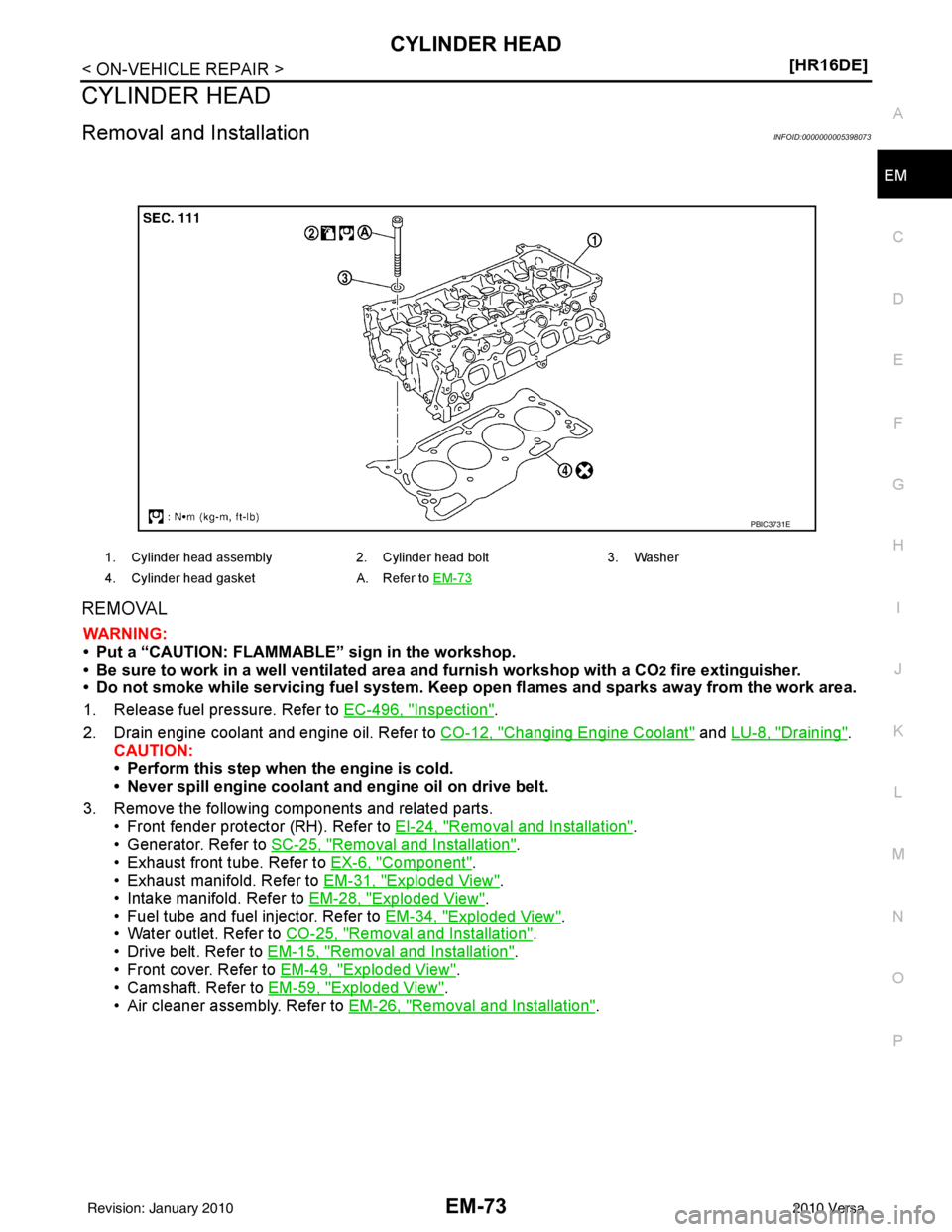
1. Cylinder head assembly 2. Cylinder head bolt3. Washer
4. Cylinder head gasket A. Refer to EM-73
PBIC3731E
Revision: January 20102010 Versa
Page 2442 of 3745
ENGINE ASSEMBLYEM-83
< REMOVAL AND INSTALLATION > [HR16DE]
C
D
E
F
G H
I
J
K L
M A
EM
NP
O
• If items or work required are not covered by the engine section, follow the procedures in the applica-
ble sections.
• Always use the support poin t specified for lifting.
• Use either 2-pole lift type or separate type lift as best you can. If board-on type is used for unavoid-
able reasons, support at the rear axle jacking point with a transmission jack or similar tool before
starting work, in preparation for the backward shif t of center of gravity.
• For supporting points fo r lifting and jacking point at rear axle, refer to GI-38, "
Garage Jack and
Safety Stand and 2-Pole Lift".
REMOVAL
Outline
Remove the engine and the transaxle assembly from t he vehicle downward. Separate the engine and the tran-
saxle.
Preparation
1. Remove the hood assembly. Refer to BL-14, "Removal and Installation".
2. Remove the cowl top cover and cowl top extension assembly. Refer to EI-22, "
Removal and Installation".
3. Release fuel pressure. Refer to EC-496, "
Inspection".
4. Drain engine coolant from radiator. Refer to CO-12, "
Changing Engine Coolant".
CAUTION:
• Perform this step when the engine is cold.
• Never spill engine coolant on drive belt.
5. Drain the transmission fluid. Refer to MT-11, "
Draining" (M/T).
6. Remove the following parts. • Engine under cover. Refer to EI-15, "
Removal and Installation".
• Front road wheels and tires. Refer to WT-7, "
Adjustment".
• Front fender protector (RH and LH). Refer to EI-24, "
Removal and Installation".
• Battery and battery tray. Refer to SC-7, "
Removal and Installation".
• Drive belt. Refer to EM-15, "
Removal and Installation".
• Air duct and air cleaner case assembly. Refer to EM-26, "
Exploded View".
• Radiator hose (upper and lower). Refer to CO-17, "
Component".
• Disconnect cooling fan controller wiring harness.
• Remove coolant reservoir tank.
• Remove fan shroud and cooling fan assembly. Refer to CO-19, "
Component (Models with A/C)" or CO-
19, "Component (Models without A/C)".
Engine Room LH
1. Disconnect all connections of engine harness around the engine mounting insulator (LH), and then tem-
porarily secure the engine harness into the engine side.
CAUTION:
Protect connectors using a resin bag against foreign materials.
2. Remove ground cable at transaxle side.
3. Disconnect fuel feed hose at engine side. Refer to EM-34, "
Exploded View".
4. Disconnect EVAP purge hose and brake booster vacuum hose.
5. Disconnect heater hoses, and install plugs them to prevent engine coolant from draining. Refer to CO-17,
"Component".
6. Disconnect control linkage from transaxle. Refer to AT-213, "
A/T Shift Selector Removal and Installation"
(A/T), MT-14, "Exploded View" (M/T).
7. Disconnect the clutch tube at tr ansmission side (if equipped). Refer to CL-15, "
Removal and Installation".
Engine Room RH
1. Remove ground cable between front cover and vehicle.
2. Remove generator and generator br acket (A/C models). Refer to SC-25, "
Removal and Installation".
3. Remove A/C compressor with piping connected from t he engine. Temporarily secure it on the vehicle side
with a rope to avoid putting load on it (if equipped). Refer to MTC-79, "
Removal and Installation of Com-
pressor - HR16DE".
Vehicle Underbody
Revision: January 20102010 Versa
Page 2470 of 3745
SERVICE DATA AND SPECIFICATIONS (SDS)EM-111
< SERVICE DATA AND SPECIFICATIONS (SDS) [HR16DE]
C
D
E
F
G H
I
J
K L
M A
EM
NP
O
SERVICE DATA AND SPECIFICATIONS (SDS)
SERVICE DATA AND SPECIFICATIONS (SDS)
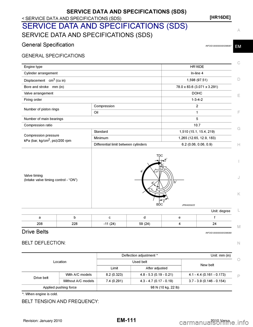
General SpecificationINFOID:0000000005398087
GENERAL SPECIFICATIONS
Drive BeltsINFOID:0000000005398088
BELT DEFLECTION:
*: When engine is cold.
BELT TENSION AND FREQUENCY:
Engine type
HR16DE
Cylinder arrangement In-line 4
Displacement cm
3 (cu in) 1,598 (97.51)
Bore and stroke mm (in) 78.0 x 83.6 (3.071 x 3.291)
Valve arrangement DOHC
Firing order 1-3-4-2
Number of piston rings Compression 2
Oil 1
Number of main bearings 5
Compression ratio 10.7
Compression pressure
kPa (bar, kg/cm
2, psi)/200 rpm Standard 1,510 (15.1, 15.4, 219)
Minimum
1,265 (12.65, 12.9, 183)
Differential limit between cylinders 6.2 (0.06, 0.06, 0.9)
Valve timing
(Intake valve timing control - “ON”) Unit: degree
abcde f
208 228-11 (24) 59 (24) 424
JPBIA0552ZZ
Location Deflection adjustment *
Unit: mm (in)
Used belt New belt
Limit After adjusted
Drive belt With A/C models 8.2 (0.323) 4.8 - 5.3 (0.19 - 0.21) 4.1 - 4.4 (0.161 - 0.173)
Without A/C models 7.4 (0.291) 4.3 - 4.7 (0.17 - 0.19) 3.7 - 3.9 (0.146 - 0.154)
Applied pushing force 98 N (10 kg, 22 lb)
Revision: January 20102010 Versa
Page 2471 of 3745
EM-112
< SERVICE DATA AND SPECIFICATIONS (SDS) [HR16DE]
SERVICE DATA AND SPECIFICATIONS (SDS)
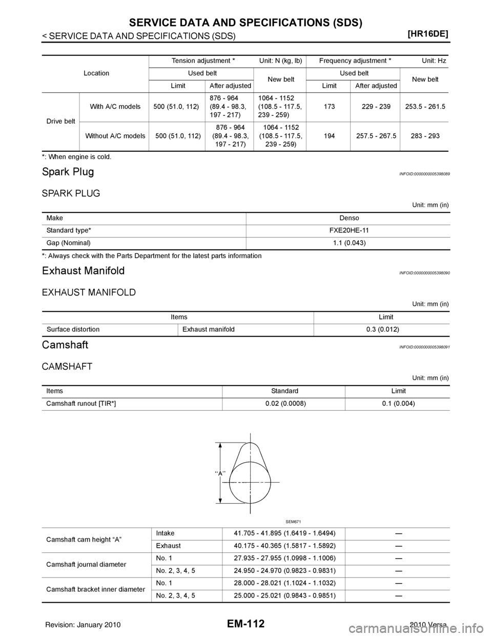
*: When engine is cold.
Spark PlugINFOID:0000000005398089
SPARK PLUG
Unit: mm (in)
*: Always check with the Parts Department for the latest parts information
Exhaust ManifoldINFOID:0000000005398090
EXHAUST MANIFOLD
Unit: mm (in)
CamshaftINFOID:0000000005398091
CAMSHAFT
Unit: mm (in)
Location Tension adjustment * Unit: N (kg, lb) Frequency adjustment * Unit: Hz
Used belt New beltUsed belt
New belt
Limit After adjusted Limit After adjusted
Drive belt With A/C models 500 (51.0, 112)
876 - 964
(89.4 - 98.3,
197 - 217)1064 - 1152
(108.5 - 117.5,
239 - 259)
173 229 - 239 253.5 - 261.5
Without A/C models 500 (51.0, 112) 876 - 964
(89.4 - 98.3, 197 - 217) 1064 - 1152
(108.5 - 117.5, 239 - 259) 194 257.5 - 267.5 283 - 293
Make
Denso
Standard type* FXE20HE-11
Gap (Nominal) 1.1 (0.043)
Items Limit
Surface distortion Exhaust manifold 0.3 (0.012)
Items StandardLimit
Camshaft runout [TIR*] 0.02 (0.0008)0.1 (0.004)
Camshaft cam height “A” Intake
41.705 - 41.895 (1.6419 - 1.6494) —
Exhaust 40.175 - 40.365 (1.5817 - 1.5892) —
Camshaft journal diameter No. 1
27.935 - 27.955 (1.0998 - 1.1006) —
No. 2, 3, 4, 5 24.950 - 24.970 (0.9823 - 0.9831) —
Camshaft bracket inner diameter No. 1
28.000 - 28.021 (1.1024 - 1.1032) —
No. 2, 3, 4, 5 25.000 - 25.021 (0.9843 - 0.9851) —
SEM671
Revision: January 20102010 Versa