belt NISSAN TIIDA 2010 Service Workshop Manual
[x] Cancel search | Manufacturer: NISSAN, Model Year: 2010, Model line: TIIDA, Model: NISSAN TIIDA 2010Pages: 3745, PDF Size: 73.67 MB
Page 1271 of 3745
EC-6
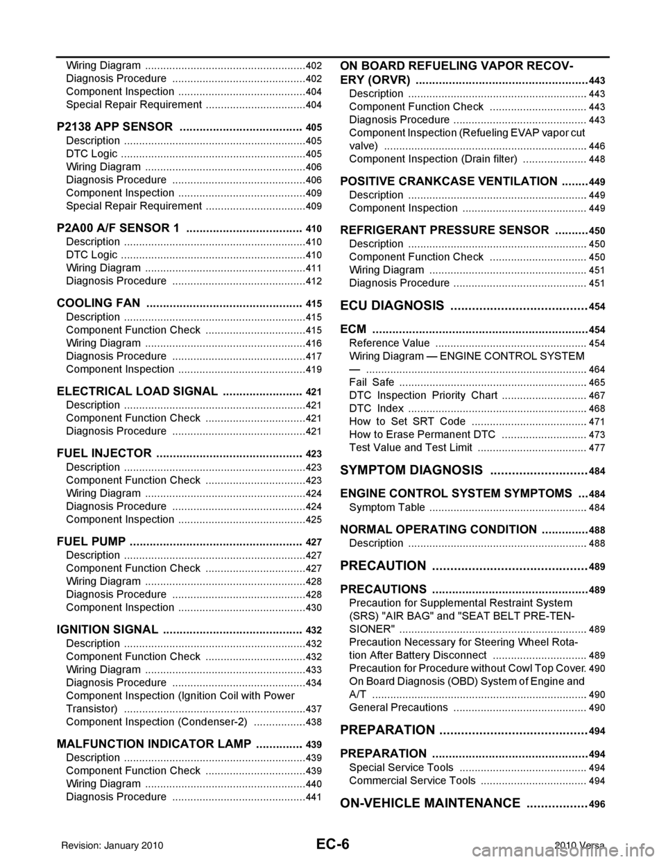
Wiring Diagram ......................................................402
Diagnosis Procedure .............................................402
Component Inspection ...........................................404
Special Repair Requirement ..................................404
P2138 APP SENSOR ..................................... .405
Description ........................................................... ..405
DTC Logic ..............................................................405
Wiring Diagram ......................................................406
Diagnosis Procedure .............................................406
Component Inspection ...........................................409
Special Repair Requirement ..................................409
P2A00 A/F SENSOR 1 ................................... .410
Description ........................................................... ..410
DTC Logic ..............................................................410
Wiring Diagram ......................................................411
Diagnosis Procedure .............................................412
COOLING FAN ................................................415
Description ........................................................... ..415
Component Function Check ..................................415
Wiring Diagram ......................................................416
Diagnosis Procedure .............................................417
Component Inspection ...........................................419
ELECTRICAL LOAD SIGNAL .........................421
Description ........................................................... ..421
Component Function Check ..................................421
Diagnosis Procedure .............................................421
FUEL INJECTOR .............................................423
Description ........................................................... ..423
Component Function Check ..................................423
Wiring Diagram ......................................................424
Diagnosis Procedure .............................................424
Component Inspection ...........................................425
FUEL PUMP .....................................................427
Description ........................................................... ..427
Component Function Check ..................................427
Wiring Diagram ......................................................428
Diagnosis Procedure .............................................428
Component Inspection ...........................................430
IGNITION SIGNAL ...........................................432
Description ........................................................... ..432
Component Function Check ..................................432
Wiring Diagram ......................................................433
Diagnosis Procedure .............................................434
Component Inspection (Ignition Coil with Power
Transistor) .............................................................
437
Component Inspection (Condenser-2) ..................438
MALFUNCTION INDICATOR LAMP ...............439
Description ........................................................... ..439
Component Function Check ..................................439
Wiring Diagram ......................................................440
Diagnosis Procedure .............................................441
ON BOARD REFUELING VAPOR RECOV-
ERY (ORVR) .....................................................
443
Description ........................................................... .443
Component Function Check .................................443
Diagnosis Procedure .............................................443
Component Inspection (Refueling EVAP vapor cut
valve) ................................................................... .
446
Component Inspection (Drain filter) ......................448
POSITIVE CRANKCASE VENTILATION .........449
Description ........................................................... .449
Component Inspection ..........................................449
REFRIGERANT PRESSURE SENSOR ...........450
Description ........................................................... .450
Component Function Check .................................450
Wiring Diagram .....................................................451
Diagnosis Procedure .............................................451
ECU DIAGNOSIS ......................................454
ECM ................................................................ ..454
Reference Value .................................................. .454
Wiring Diagram — ENGINE CONTROL SYSTEM
— ..........................................................................
464
Fail Safe ...............................................................465
DTC Inspection Priority Chart .............................467
DTC Index ............................................................468
How to Set SRT Code .......................................471
How to Erase Permanent DTC .............................473
Test Value and Test Limit .....................................477
SYMPTOM DIAGNOSIS ...........................484
ENGINE CONTROL SYSTEM SYMPTOMS .. ..484
Symptom Table .................................................... .484
NORMAL OPERATING CONDITION ...............488
Description ........................................................... .488
PRECAUTION ...........................................489
PRECAUTIONS .............................................. ..489
Precaution for Supplemental Restraint System
(SRS) "AIR BAG" and "SEAT BELT PRE-TEN-
SIONER" .............................................................. .
489
Precaution Necessary for Steering Wheel Rota-
tion After Battery Disconnect ................................
489
Precaution for Procedure without Cowl Top Cover .490
On Board Diagnosis (OBD) System of Engine and
A/T ........................................................................
490
General Precautions .............................................490
PREPARATION .........................................494
PREPARATION .............................................. ..494
Special Service Tools .......................................... .494
Commercial Service Tools ....................................494
ON-VEHICLE MAINTENANCE .................496
Revision: January 20102010 Versa
Page 1272 of 3745
EC-7
C
DE
F
G H
I
J
K L
M
EC A
N
O P
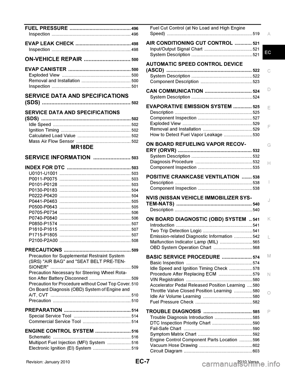
FUEL PRESSURE .......................................... ..496
Inspection ............................................................ ..496
EVAP LEAK CHECK ........................................498
Inspection ............................................................ ..498
ON-VEHICLE REPAIR ...............................500
EVAP CANISTER .............................................500
Exploded View .................................................... ..500
Removal and Installation .......................................500
Inspection ............................................................ ..501
SERVICE DATA AND SPECIFICATIONS
(SDS) ......... ................................. ................
502
SERVICE DATA AND SPECIFICATIONS
(SDS) .............................................................. ..
502
Idle Speed ........................................................... ..502
Ignition Timing .......................................................502
Calculated Load Value ..........................................502
Mass Air Flow Sensor ...........................................502
MR18DE
SERVICE INFORMATION .. .......................
503
INDEX FOR DTC ............................................ ..503
U0101-U1001 ...................................................... ..503
P0011-P0075 ........................................................503
P0101-P0128 ........................................................503
P0130-P0183 ........................................................504
P0222-P0420 ........................................................504
P0441-P0463 ........................................................505
P0500-P0643 ........................................................505
P0705-P0734 ........................................................506
P0740-P0840 ........................................................506
P0850-P1574 ........................................................507
P1610-P1615 ........................................................507
P1715-P1805 ........................................................507
P2100-P2A00 ........................................................508
PRECAUTIONS ................................................509
Precaution for Supplemental Restraint System
(SRS) "AIR BAG" and "SEAT BELT PRE-TEN-
SIONER" ............................................................. ..
509
Precaution Necessary for Steering Wheel Rota-
tion After Battery Disconnect ............................... ..
509
Precaution for Procedure without Cowl Top Cover ..510
On Board Diagnosis (OBD) System of Engine and
A/T, CVT ...............................................................
510
Precaution .............................................................510
PREPARATION ................................................514
Special Service Tool ........................................... ..514
Commercial Service Tool ......................................514
ENGINE CONTROL SYSTEM ..........................516
Schematic ........................................................... ..516
Multiport Fuel Injection (MFI) System ...................516
Electronic Ignition (EI) System ..............................519
Fuel Cut Control (at No Load and High Engine
Speed) ................................................................. ..
519
AIR CONDITIONING CUT CONTROL ............521
Input/Output Signal Chart ......................................521
System Description ................................................521
AUTOMATIC SPEED CONTROL DEVICE
(ASCD) ............................................................
522
System Description ................................................522
Component Description .........................................523
CAN COMMUNICATION .................................524
System Description ................................................524
EVAPORATIVE EMISSION SYSTEM .............525
Description .............................................................525
Component Inspection ...........................................527
Exploded View .......................................................529
Removal and Installation .......................................529
How to Detect Fuel Vapor Leakage .......................530
ON BOARD REFUELING VAPOR RECOV-
ERY (ORVR) ....................................................
532
System Description ................................................532
Diagnosis Procedure .............................................532
Component Inspection ...........................................535
POSITIVE CRANKCASE VENTILATION .......538
Description .............................................................538
Component Inspection ...........................................538
NVIS (NISSAN VEHICLE IMMOBILIZER SYS-
TEM-NATS) .....................................................
540
Description .............................................................540
ON BOARD DIAGNOSTIC (OBD) SYSTEM ..541
Introduction ............................................................541
Two Trip Detection Logic .......................................541
Emission-related Diagnostic Information ...............542
Malfunction Indicator Lamp (MIL) ..........................565
OBD System Operation Chart ...............................568
BASIC SERVICE PROCEDURE .....................574
Basic Inspection ....................................................574
Idle Speed and Ignition Timing Check ...................578
Procedure After Replacing ECM ...........................579
VIN Registration ....................................................580
Accelerator Pedal Released Position Learning .....580
Throttle Valve Closed Position Learning ...............580
Idle Air Volume Learning .......................................580
Fuel Pressure Check .............................................582
TROUBLE DIAGNOSIS ..................................585
Trouble Diagnosis Introduction ..............................585
DTC Inspection Priority Chart ................................590
Fail-Safe Chart ......................................................590
Symptom Matrix Chart ...........................................592
Engine Control Component Parts Location ...........596
Vacuum Hose Drawing ..........................................602
Circuit Diagram ......................................................603
Revision: January 20102010 Versa
Page 1376 of 3745

TROUBLE DIAGNOSIS - SPECIFICATION VALUEEC-111
< COMPONENT DIAGNOSIS > [HR16DE]
C
D
E
F
G H
I
J
K L
M A
EC
NP
O
2. Disconnect ECM harness connector.
3. Check pin terminal and connector for damage, and then reconnect it.
>> GO TO 16.
16.CHECK “A/F ALPHA-B1”
1. Start engine.
2. Select “A/F ALPHA-B1” in “SPEC” of “DATA MONITOR” mode, and make sure that the indication is within
the SP value.
Is the measurement value within the SP value?
YES >> INSPECTION END
NO >> Detect malfunctioning part according to EC-484, "
Symptom Table".
17.CHECK “B/FUEL SCHDL”
Select “B/FUEL SCHDL” in “SPEC” of “DATA MONITOR” m ode, and make sure that the indication is within the
SP value.
Is the measurement value within the SP value?
YES >> INSPECTION END
NO-1 >> More than the SP value: GO TO 18.
NO-2 >> Less than the SP value: GO TO 25.
18.DETECT MALFUNCTIONING PART
1. Check for the cause of large engine friction. Refer to the following.
- Engine oil level is too high
- Engine oil viscosity
- Belt tension of power steering, alternator, A/C compressor, etc. is excessive
- Noise from engine
- Noise from transmission, etc.
2. Check for the cause of insufficient combustion. Refer to the following.
- Valve clearance malfunction
- Intake valve timing control function malfunction
- Camshaft sprocket installation malfunction, etc.
>> Repair or replace malfunctioning part, and then GO TO 30.
19.CHECK INTAKE SYSTEM
Check for the cause of uneven air flow through mass air flow sensor. Refer to the following.
• Crushed air ducts
• Malfunctioning seal of air cleaner element
• Uneven dirt of air cleaner element
• Improper specification of intake air system
Is the inspection result normal?
YES >> GO TO 21.
NO >> Repair or replace malfunctioning part, and then GO TO 20.
20.CHECK “A/F ALPHA-B1”, AND “B/FUEL SCHDL”
Select “A/F ALPHA-B1” and “B/FUEL SCHDL” in “SPEC” of “DATA MONITOR” mode, and make sure that
each indication is within the SP value.
Is the measurement value within the SP value?
YES >> INSPECTION END
NO >> “B/FUEL SCHDL” is more, “A/F ALPHA-B1” is less than the SP value: GO TO 21.
21.DISCONNECT AND RECONNECT MASS AI R FLOW SENSOR HARNESS CONNECTOR
1. Stop the engine.
2. Disconnect mass air flow sensor harness connector.
3. Check pin terminal and connector for damage and then reconnect it again.
>> GO TO 22.
Revision: January 20102010 Versa
Page 1754 of 3745

PRECAUTIONSEC-489
< PRECAUTION > [HR16DE]
C
D
E
F
G H
I
J
K L
M A
EC
NP
O
PRECAUTION
PRECAUTIONS
Precaution for Supplemental
Restraint System (SRS) "AIR BAG" and "SEAT BELT
PRE-TENSIONER"
INFOID:0000000006046361
The Supplemental Restraint System such as “AIR BAG” and “SEAT BELT PRE-TENSIONER”, used along
with a front seat belt, helps to reduce the risk or severi ty of injury to the driver and front passenger for certain
types of collision. This system includes seat belt switch inputs and dual stage front air bag modules. The SRS
system uses the seat belt switches to determine the front air bag deployment, and may only deploy one front
air bag, depending on the severity of a collision and w hether the front occupants are belted or unbelted.
Information necessary to service the system safely is included in the SRS and SB section of this Service Man-
ual.
WARNING:
• To avoid rendering the SRS inoper ative, which could increase the risk of personal injury or death in
the event of a collision which would result in air bag inflation, all maintenance must be performed by
an authorized NISSAN/INFINITI dealer.
• Improper maintenance, including in correct removal and installation of the SRS can lead to personal
injury caused by unintentional act ivation of the system. For removal of Spiral Cable and Air Bag
Module, see the SRS section.
• Do not use electrical test equipm ent on any circuit related to the SRS unless instructed to in this
Service Manual. SRS wiring harnesses can be identi fied by yellow and/or orange harnesses or har-
ness connectors.
PRECAUTIONS WHEN USING POWER TOOLS (AIR OR ELECTRIC) AND HAMMERS
WARNING:
• When working near the Airbag Diagnosis Sensor Un it or other Airbag System sensors with the Igni-
tion ON or engine running, DO NOT use air or el ectric power tools or strike near the sensor(s) with a
hammer. Heavy vibration could activate the sensor( s) and deploy the air bag(s), possibly causing
serious injury.
• When using air or electric power tools or hammers, always switch the Ignition OFF, disconnect the battery, and wait at least 3 minutes before performing any service.
Precaution Necessary for Steering Wheel Rotation After Battery Disconnect
INFOID:0000000006046362
NOTE:
• This Procedure is applied only to models with Intelligent Key system and NATS (NISSAN ANTI-THEFT SYS-
TEM).
• Remove and install all control units after disconnecti ng both battery cables with the ignition knob in the
″ LOCK ″ position.
• Always use CONSULT-III to perform self-diagnosis as a part of each function inspection after finishing work.
If DTC is detected, perform trouble diagnosis according to self-diagnostic results.
For models equipped with the Intelligent Key system and NATS , an electrically controlled steering lock mech-
anism is adopted on the key cylinder.
For this reason, if the battery is disconnected or if the battery is discharged, the steering wheel will lock and
steering wheel rotation will become impossible.
If steering wheel rotation is required when battery power is interrupted, follow the procedure below before
starting the repair operation.
OPERATION PROCEDURE
1. Connect both battery cables. NOTE:
Supply power using jumper cables if battery is discharged.
2. Use the Intelligent Key or mechanical key to turn the ignition switch to the ″ACC ″ position. At this time, the
steering lock will be released.
3. Disconnect both battery cables. The steering lock will remain released and the steering wheel can be
rotated.
4. Perform the necessary repair operation.
Revision: January 20102010 Versa
Page 1774 of 3745

PRECAUTIONSEC-509
< SERVICE INFORMATION > [MR18DE]
C
D
E
F
G H
I
J
K L
M A
EC
NP
O
PRECAUTIONS
Precaution for Supplemental
Restraint System (SRS) "AIR BAG" and "SEAT BELT
PRE-TENSIONER"
INFOID:0000000006046363
The Supplemental Restraint System such as “AIR BAG” and “SEAT BELT PRE-TENSIONER”, used along
with a front seat belt, helps to reduce the risk or severi ty of injury to the driver and front passenger for certain
types of collision. This system includes seat belt switch inputs and dual stage front air bag modules. The SRS
system uses the seat belt switches to determine the front air bag deployment, and may only deploy one front
air bag, depending on the severity of a collision and w hether the front occupants are belted or unbelted.
Information necessary to service the system safely is included in the SRS and SB section of this Service Man-
ual.
WARNING:
• To avoid rendering the SRS inoper ative, which could increase the risk of personal injury or death in
the event of a collision which would result in air bag inflation, all maintenance must be performed by
an authorized NISSAN/INFINITI dealer.
• Improper maintenance, including in correct removal and installation of the SRS can lead to personal
injury caused by unintentional act ivation of the system. For removal of Spiral Cable and Air Bag
Module, see the SRS section.
• Do not use electrical test equipm ent on any circuit related to the SRS unless instructed to in this
Service Manual. SRS wiring harnesses can be identi fied by yellow and/or orange harnesses or har-
ness connectors.
PRECAUTIONS WHEN USING POWER TOOLS (AIR OR ELECTRIC) AND HAMMERS
WARNING:
• When working near the Airbag Diagnosis Sensor Un it or other Airbag System sensors with the Igni-
tion ON or engine running, DO NOT use air or el ectric power tools or strike near the sensor(s) with a
hammer. Heavy vibration could activate the sensor( s) and deploy the air bag(s), possibly causing
serious injury.
• When using air or electric power tools or hammers, always switch the Ignition OFF, disconnect the battery, and wait at least 3 minutes before performing any service.
Precaution Necessary for Steering Wheel Rotation After Battery Disconnect
INFOID:0000000006046364
NOTE:
• This Procedure is applied only to models with Intelligent Key system and NATS (NISSAN ANTI-THEFT SYS-
TEM).
• Remove and install all control units after disconnecti ng both battery cables with the ignition knob in the
″ LOCK ″ position.
• Always use CONSULT-III to perform self-diagnosis as a part of each function inspection after finishing work.
If DTC is detected, perform trouble diagnosis according to self-diagnostic results.
For models equipped with the Intelligent Key system and NATS , an electrically controlled steering lock mech-
anism is adopted on the key cylinder.
For this reason, if the battery is disconnected or if the battery is discharged, the steering wheel will lock and
steering wheel rotation will become impossible.
If steering wheel rotation is required when battery power is interrupted, follow the procedure below before
starting the repair operation.
OPERATION PROCEDURE
1. Connect both battery cables.
NOTE:
Supply power using jumper cables if battery is discharged.
2. Use the Intelligent Key or mechanical key to turn the ignition switch to the ″ACC ″ position. At this time, the
steering lock will be released.
3. Disconnect both battery cables. The steering lock will remain released and the steering wheel can be
rotated.
4. Perform the necessary repair operation.
5. When the repair work is completed, return the ignition switch to the ″LOCK ″ position before connecting
the battery cables. (At this time, the steering lock mechanism will engage.)
Revision: January 20102010 Versa
Page 1894 of 3745

TROUBLE DIAGNOSIS - SPECIFICATION VALUEEC-629
< SERVICE INFORMATION > [MR18DE]
C
D
E
F
G H
I
J
K L
M A
EC
NP
O
OK >>
INSPECTION END
NG >> GO TO 15.
15.DISCONNECT AND RECONNECT ECM HARNESS CONNECTOR
1. Stop the engine.
2. Disconnect ECM harness connector. Check pin term inal and connector for damage, and then reconnect it.
>> GO TO 16.
16.CHECK “A/F ALPHA-B1”
1. Start engine.
2. Select “A/F ALPHA-B1” in “SPEC” of “DATA MONITOR” mode, and make sure that the indication is within
the SP value.
OK or NG
OK >> INSPECTION END
NG >> Detect malfunctioning part according to EC-592, "
Symptom Matrix Chart".
17.CHECK “B/FUEL SCHDL”
Select “B/FUEL SCHDL” in “SPEC” of “DATA MONITOR” m ode, and make sure that the indication is within the
SP value.
OK or NG
OK >> INSPECTION END
NG (More than the SP value)>>GO TO 18.
NG (Less than the SP value)>>GO TO 25.
18.DETECT MALFUNCTIONING PART
1. Check for the cause of large engine friction. Refer to the following.
- Engine oil level is too high
- Engine oil viscosity
- Belt tension of alternator, A/C compressor, etc. is excessive
- Noise from engine
- Noise from transmission, etc.
2. Check for the cause of insufficient combustion. Refer to the following.
- Valve clearance malfunction
- Intake valve timing control function malfunction
- Camshaft sprocket installation malfunction, etc.
>> Repair or replace malfunctioning part, and then GO TO 30.
19.CHECK INTAKE SYSTEM
Check for the cause of uneven air flow through mass air flow sensor. Refer to the following.
• Crushed air ducts
• Malfunctioning seal of air cleaner element
• Uneven dirt of air cleaner element
• Improper specification of intake air system
OK or NG
OK >> GO TO 21.
NG >> Repair or replace malfunctioning part, and then GO TO 20.
20.CHECK “A/F ALPHA-B1” AND “B/FUEL SCHDL”
Select “A/F ALPHA-B1” and “B/FUEL SCHDL” in “SPEC” of “DATA MONITOR” mode, and make sure that the
each indication is within the SP value.
OK or NG
OK >> INSPECTION END
NG (“B/FUEL SCHDL” is more, “A/F ALPHA- B1” is less than the SP value)>>GO TO 21.
21.DISCONNECT AND RECONNECT MASS AI R FLOW SENSOR HARNESS CONNECTOR
1. Stop the engine.
Revision: January 20102010 Versa
Page 2302 of 3745
EI-1
BODY
C
DE
F
G H
J
K L
M
SECTION EI
A
B
EI
N
O P
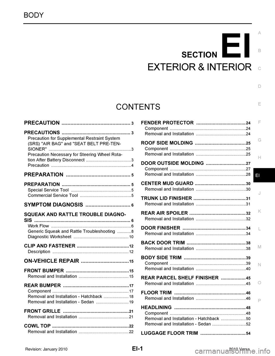
CONTENTS
EXTERIOR & INTERIOR
PRECAUTION ....... ........................................3
PRECAUTIONS .............................................. .....3
Precaution for Supplemental Restraint System
(SRS) "AIR BAG" and "SEAT BELT PRE-TEN-
SIONER" ............................................................. ......
3
Precaution Necessary for Steering Wheel Rota-
tion After Battery Disconnect ............................... ......
3
Precaution .................................................................4
PREPARATION ............................................5
PREPARATION .............................................. .....5
Special Service Tool ........................................... ......5
Commercial Service Tool ..........................................5
SYMPTOM DIAGNOSIS ...............................6
SQUEAK AND RATTLE TROUBLE DIAGNO-
SIS .................................................................. .....
6
Work Flow ........................................................... ......6
Generic Squeak and Rattle Troubleshooting ............8
Diagnostic Worksheet .............................................10
CLIP AND FASTENER .......................................12
Description .......................................................... ....12
ON-VEHICLE REPAIR .................................15
FRONT BUMPER ........................................... ....15
Removal and Installation .........................................15
REAR BUMPER ............................................. ....17
Component .......................................................... ....17
Removal and Installation - Hatchback .....................18
Removal and Installation - Sedan ....................... ....19
FRONT GRILLE .................................................21
Removal and Installation .........................................21
COWL TOP .........................................................22
Removal and Installation .........................................22
FENDER PROTECTOR ....................................24
Component .......................................................... ....24
Removal and Installation .........................................24
ROOF SIDE MOLDING .....................................25
Component ..............................................................25
Removal and Installation .........................................25
DOOR OUTSIDE MOLDING .............................27
Component ..............................................................27
Removal and Installation .........................................28
CENTER MUD GUARD .....................................30
Removal and Installation .........................................30
TRUNK LID FINISHER ......................................31
Removal and Installation .........................................31
REAR AIR SPOILER .........................................32
Removal and Installation .........................................32
DOOR FINISHER ..............................................34
Removal and Installation .........................................34
BACK DOOR TRIM ...........................................38
Removal and Installation ..................................... ....38
BODY SIDE TRIM .............................................39
Component ..............................................................39
Removal and Installation .........................................40
REAR PARCEL SHELF FINISHER ..................45
Removal and Installation .........................................45
FLOOR TRIM ....................................................46
Removal and Installation .........................................46
HEADLINING ....................................................48
Component ..............................................................48
Removal and Installation - Hatchback .....................50
Removal and Installation - Sedan ............................52
LUGGAGE FLOOR TRIM .................................54
Revision: January 20102010 Versa
Page 2304 of 3745
PRECAUTIONSEI-3
< PRECAUTION >
C
DE
F
G H
J
K L
M A
B
EI
N
O P
PRECAUTION
PRECAUTIONS
Precaution for Supplemental Restraint System (SRS) "AIR BAG" and "SEAT BELT
PRE-TENSIONER"
INFOID:0000000005714352
The Supplemental Restraint System such as “AIR BAG” and “SEAT BELT PRE-TENSIONER”, used along
with a front seat belt, helps to reduce the risk or severi ty of injury to the driver and front passenger for certain
types of collision. This system includes seat belt switch inputs and dual stage front air bag modules. The SRS
system uses the seat belt switches to determine the front air bag deployment, and may only deploy one front
air bag, depending on the severity of a collision and w hether the front occupants are belted or unbelted.
Information necessary to service the system safely is included in the SRS and SB section of this Service Man-
ual.
WARNING:
• To avoid rendering the SRS inoper ative, which could increase the risk of personal injury or death in
the event of a collision which would result in air bag inflation, all maintenance must be performed by
an authorized NISSAN/INFINITI dealer.
• Improper maintenance, including in correct removal and installation of the SRS, can lead to personal
injury caused by unintentional act ivation of the system. For removal of Spiral Cable and Air Bag
Module, see the SRS section.
• Do not use electrical test equipm ent on any circuit related to the SRS unless instructed to in this
Service Manual. SRS wiring harnesses can be identi fied by yellow and/or orange harnesses or har-
ness connectors.
PRECAUTIONS WHEN USING POWER TOOLS (AIR OR ELECTRIC) AND HAMMERS
WARNING:
• When working near the Airbag Diagnosis Sensor Un it or other Airbag System sensors with the Igni-
tion ON or engine running, DO NOT use air or el ectric power tools or strike near the sensor(s) with a
hammer. Heavy vibration could activate the sensor( s) and deploy the air bag(s), possibly causing
serious injury.
• When using air or electric power tools or hammers, always switch the Ignition OFF, disconnect the battery, and wait at least 3 minutes before performing any service.
Precaution Necessary for Steering Wheel Rotation After Battery Disconnect
INFOID:0000000005396814
NOTE:
• This Procedure is applied only to models with Intelligent Key system and NATS (NISSAN ANTI-THEFT SYS-
TEM).
• Remove and install all control units after disconnecti ng both battery cables with the ignition knob in the
″ LOCK ″ position.
• Always use CONSULT-III to perform self-diagnosis as a part of each function inspection after finishing work.
If DTC is detected, perform trouble diagnosis according to self-diagnostic results.
For models equipped with the Intelligent Key system and NATS , an electrically controlled steering lock mech-
anism is adopted on the key cylinder.
For this reason, if the battery is disconnected or if the battery is discharged, the steering wheel will lock and
steering wheel rotation will become impossible.
If steering wheel rotation is required when battery power is interrupted, follow the procedure below before
starting the repair operation.
OPERATION PROCEDURE
1. Connect both battery cables. NOTE:
Supply power using jumper cables if battery is discharged.
2. Use the Intelligent Key or mechanical key to turn the ignition switch to the ″ACC ″ position. At this time, the
steering lock will be released.
3. Disconnect both battery cables. The steering lock will remain released and the steering wheel can be
rotated.
4. Perform the necessary repair operation.
Revision: January 20102010 Versa
Page 2344 of 3745
BODY SIDE TRIMEI-43
< ON-VEHICLE REPAIR >
C
DE
F
G H
J
K L
M A
B
EI
N
O P
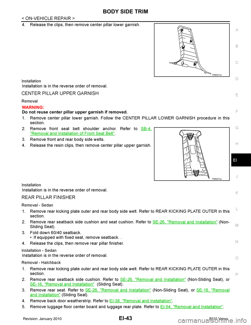
4. Release the clips, then remove center pillar lower garnish.
Installation
Installation is in the reverse order of removal.
CENTER PILLAR UPPER GARNISH
Removal
WARNING:
Do not reuse center pillar upper garnish if removed.
1. Remove center pillar lower garnish. Follow t he CENTER PILLAR LOWER GARNISH procedure in this
section.
2. Remove front seat belt shoulder anchor. Refer to SB-4,
"Removal and Installation of Front Seat Belt".
3. Remove front and rear body side welts.
4. Release the resin clips, then remove center pillar upper garnish.
Installation
Installation is in the reverse order of removal.
REAR PILLAR FINISHER
Removal - Sedan
1. Remove rear kicking plate outer and rear body side welt. Refer to REAR KICKING PLATE OUTER in this
section.
2. Remove rear seatback side cushion and seat cushion. Refer to SE-26, "
Removal and Installation" (Non-
Sliding Seat).
3. Fold down 60/40 seatback. • If equipped with fixed seat, remove seatback. .
4. Release the clips, then remove rear pillar finisher.
Installation - Sedan
Installation is in the reverse order of removal.
Removal - Hatchback
1. Remove rear kicking plate outer and rear body side welt. Refer to REAR KICKING PLATE OUTER in this
section.
2. Remove rear seatback side cushion. Refer to SE-26, "
Removal and Installation" (Non-Sliding Seat), or
SE-16, "
Removal and Installation" (Sliding Seat).
3. Remove rear seat. Refer to SE-26, "
Removal and Installation" (Non-Sliding Seat), or SE-16, "Removal
and Installation" (Sliding Seat).
4. Remove back door weatherstrip. Refer to EI-38, "
Removal and Installation".
5. Remove luggage floor center board and luggage rear plate. Refer to EI-54, "
Removal and Installation".
PIIB2574J
PIIB2575J
Revision: January 20102010 Versa
Page 2345 of 3745
EI-44
< ON-VEHICLE REPAIR >
BODY SIDE TRIM
6. Remove luggage side lower finisher. Refer to EI-54, "Removal and Installation".
7. Remove rear seat belt outer anchor bolt. Refer to SB-6, "
Removal and Installation of Rear Seat Belt".
8. Release the clips, then remove rear pillar finisher.
Installation - Hatchback
Installation is in the reverse order of removal.
Revision: January 20102010 Versa