cooling NISSAN TIIDA 2010 Service Manual PDF
[x] Cancel search | Manufacturer: NISSAN, Model Year: 2010, Model line: TIIDA, Model: NISSAN TIIDA 2010Pages: 3745, PDF Size: 73.67 MB
Page 1880 of 3745
TROUBLE DIAGNOSISEC-615
< SERVICE INFORMATION > [MR18DE]
C
D
E
F
G H
I
J
K L
M A
EC
NP
O
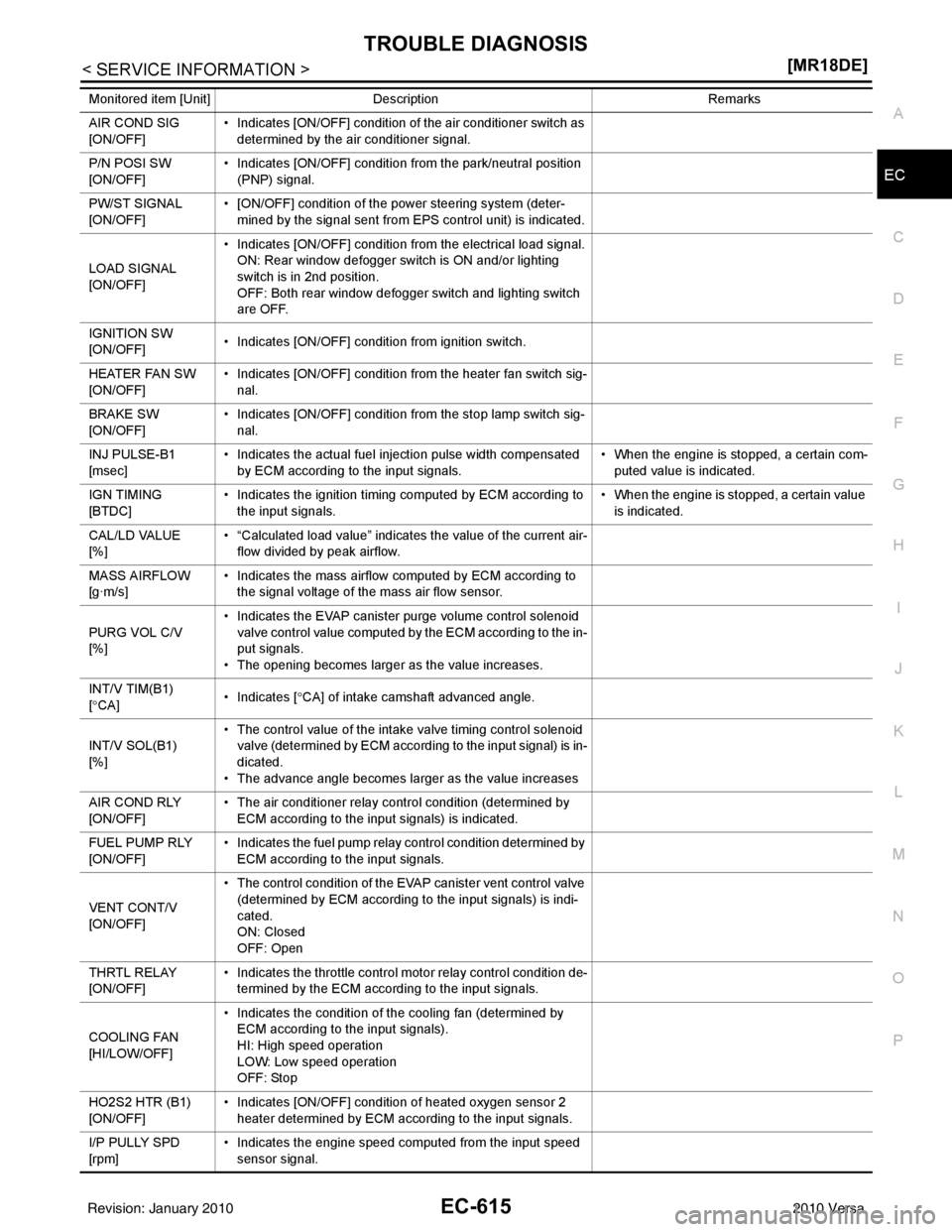
AIR COND SIG
[ON/OFF]
• Indicates [ON/OFF] condition of the air conditioner switch as
determined by the air conditioner signal.
P/N POSI SW
[ON/OFF] • Indicates [ON/OFF] condition from the park/neutral position
(PNP) signal.
PW/ST SIGNAL
[ON/OFF] • [ON/OFF] condition of the power steering system (deter-
mined by the signal sent from EPS control unit) is indicated.
LOAD SIGNAL
[ON/OFF] • Indicates [ON/OFF] condition from the electrical load signal.
ON: Rear window defogger switch is ON and/or lighting
switch is in 2nd position.
OFF: Both rear window defogger switch and lighting switch
are OFF.
IGNITION SW
[ON/OFF] • Indicates [ON/OFF] condition from ignition switch.
HEATER FAN SW
[ON/OFF] • Indicates [ON/OFF] condition from the heater fan switch sig-
nal.
BRAKE SW
[ON/OFF] • Indicates [ON/OFF] condition from the stop lamp switch sig-
nal.
INJ PULSE-B1
[msec] • Indicates the actual fuel injection pulse width compensated
by ECM according to the input signals. • When the engine is stopped, a certain com-
puted value is indicated.
IGN TIMING
[BTDC] • Indicates the ignition timing computed by ECM according to
the input signals. • When the engine is stopped, a certain value
is indicated.
CAL/LD VALUE
[%] • “Calculated load value” indicates the value of the current air-
flow divided by peak airflow.
MASS AIRFLOW
[g·m/s] • Indicates the mass airflow computed by ECM according to
the signal voltage of the mass air flow sensor.
PURG VOL C/V
[%] • Indicates the EVAP canister purge volume control solenoid
valve control value computed by the ECM according to the in-
put signals.
• The opening becomes larger as the value increases.
INT/V TIM(B1)
[ ° CA] • Indicates [
°CA] of intake camshaft advanced angle.
INT/V SOL(B1)
[%] • The control value of the intake valve timing control solenoid
valve (determined by ECM according to the input signal) is in-
dicated.
• The advance angle becomes larger as the value increases
AIR COND RLY
[ON/OFF] • The air conditioner relay control condition (determined by
ECM according to the input signals) is indicated.
FUEL PUMP RLY
[ON/OFF] • Indicates the fuel pump relay control condition determined by
ECM according to the input signals.
VENT CONT/V
[ON/OFF] • The control condition of the EVAP canister vent control valve
(determined by ECM according to the input signals) is indi-
cated.
ON: Closed
OFF: Open
THRTL RELAY
[ON/OFF] • Indicates the throttle control
motor relay control condition de-
termined by the ECM according to the input signals.
COOLING FAN
[HI/LOW/OFF] • Indicates the condition of the cooling fan (determined by
ECM according to the input signals).
HI: High speed operation
LOW: Low speed operation
OFF: Stop
HO2S2 HTR (B1)
[ON/OFF] • Indicates [ON/OFF] condition of heated oxygen sensor 2
heater determined by ECM according to the input signals.
I/P PULLY SPD
[rpm] • Indicates the engine speed computed from the input speed
se ns
or signal.
Monitored item [Unit]
Description Remarks
Revision: January 20102010 Versa
Page 1882 of 3745
TROUBLE DIAGNOSISEC-617
< SERVICE INFORMATION > [MR18DE]
C
D
E
F
G H
I
J
K L
M A
EC
NP
O
NOTE:
Any monitored item that does not match the vehicle being diagnosed is deleted from the display automatically.
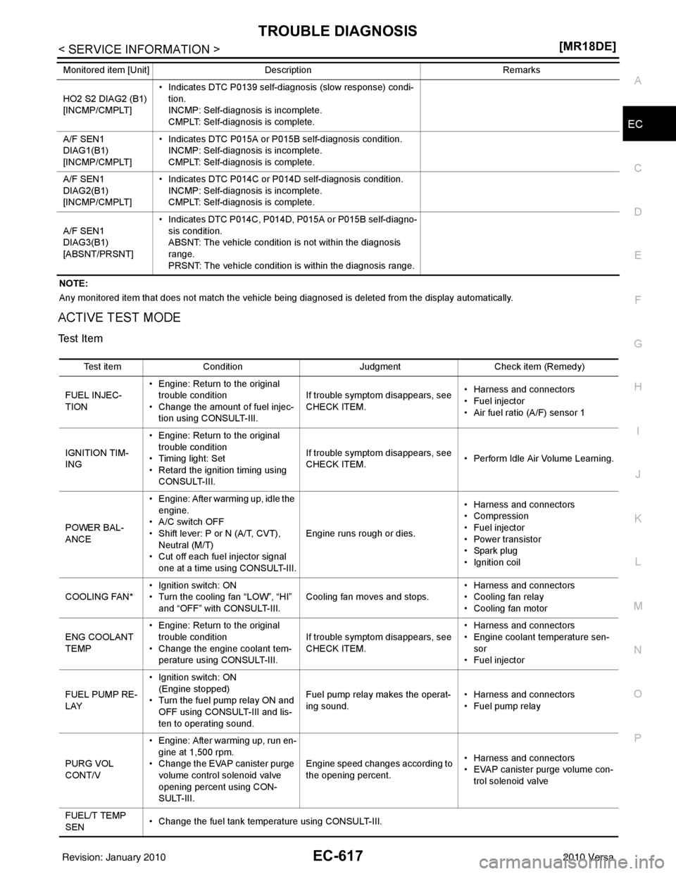
ACTIVE TEST MODE
Test Item
HO2 S2 DIAG2 (B1)
[INCMP/CMPLT]
• Indicates DTC P0139 self-diagnosis (slow response) condi-
tion.
INCMP: Self-diagnosis is incomplete.
CMPLT: Self-diagnosis is complete.
A/F SEN1
DIAG1(B1)
[INCMP/CMPLT] • Indicates DTC P015A or P015B self-diagnosis condition.
INCMP: Self-diagnosis is incomplete.
CMPLT: Self-diagnosis is complete.
A/F SEN1
DIAG2(B1)
[INCMP/CMPLT] • Indicates DTC P014C or P014D self-diagnosis condition.
INCMP: Self-diagnosis is incomplete.
CMPLT: Self-diagnosis is complete.
A/F SEN1
DIAG3(B1)
[ABSNT/PRSNT] • Indicates DTC P014C, P014D, P015A or P015B self-diagno-
sis condition.
ABSNT: The vehicle condition is not within the diagnosis
range.
PRSNT: The vehicle condition is within the diagnosis range.
Monitored item [Unit]
Description Remarks
Test itemCondition JudgmentCheck item (Remedy)
FUEL INJEC-
TION • Engine: Return to the original
trouble condition
• Change the amount of fuel injec- tion using CONSULT-III. If trouble symptom disappears, see
CHECK ITEM.
• Harness and connectors
• Fuel injector
• Air fuel ratio (A/F) sensor 1
IGNITION TIM-
ING • Engine: Return to the original
trouble condition
• Timing light: Set
• Retard the ignition timing using CONSULT-III. If trouble symptom disappears, see
CHECK ITEM.
• Perform Idle Air Volume Learning.
POWER BAL-
ANCE • Engine: After warming up, idle the
engine.
• A/C switch OFF
• Shift lever: P or N (A/T, CVT), Neutral (M/T)
• Cut off each fuel injector signal one at a time using CONSULT-III. Engine runs rough or dies.
• Harness and connectors
• Compression
• Fuel injector
• Power transistor
•Spark plug
• Ignition coil
COOLING FAN* • Ignition switch: ON
• Turn the cooling fan “LOW”, “HI”
and “OFF” with CONSULT-III. Cooling fan moves and stops.
• Harness and connectors
• Cooling fan relay
• Cooling fan motor
ENG COOLANT
TEMP • Engine: Return to the original
trouble condition
• Change the engine coolant tem-
perature using CONSULT-III. If trouble symptom disappears, see
CHECK ITEM. • Harness and connectors
• Engine coolant temperature sen-
sor
• Fuel injector
FUEL PUMP RE-
LAY • Ignition switch: ON
(Engine stopped)
• Turn the fuel pump relay ON and
OFF using CONSULT-III and lis-
ten to operating sound. Fuel pump relay makes the operat-
ing sound.
• Harness and connectors
• Fuel pump relay
PURG VOL
CONT/V • Engine: After warming up, run en-
gine at 1,500 rpm.
• Change the EVAP canister purge volume control solenoid valve
opening percent using CON-
SULT-III. Engine speed changes according to
the opening percent.
• Harness and connectors
• EVAP canister purge volume con-
trol solenoid valve
FUEL/T TEMP
SEN • Change the fuel tank temperature using CONSULT-III.
Revision: January 20102010 Versa
Page 1883 of 3745
EC-618
< SERVICE INFORMATION >[MR18DE]
TROUBLE DIAGNOSIS
*: Leaving cooling fan OFF with CONSULT-III while engine is running may cause the engine to overheat.
DTC & SRT CONFIRMATION MODE
SRT STATUS Mode
For details, refer to EC-542, "Emission-related Diagnostic Information".
PERMANENT DTC STATUS Mode
For details, refer to
EC-542, "Emission-related Diagnostic Information".
NOTE:
This mode is not used in regions that permanent DTCs are not regulated by law.
SRT WORK SUPPORT Mode
This mode enables a technician to drive a vehicle to set the SRT while monitoring the SRT status.
PERMANENT DTC WORK SUPPORT Mode
This mode enables a technician to drive a vehicle to comp lete the driving pattern that is reguired for erasing
permanent DTC.
NOTE:
This mode is not used in regions that permanent DTCs are not regulated by law.
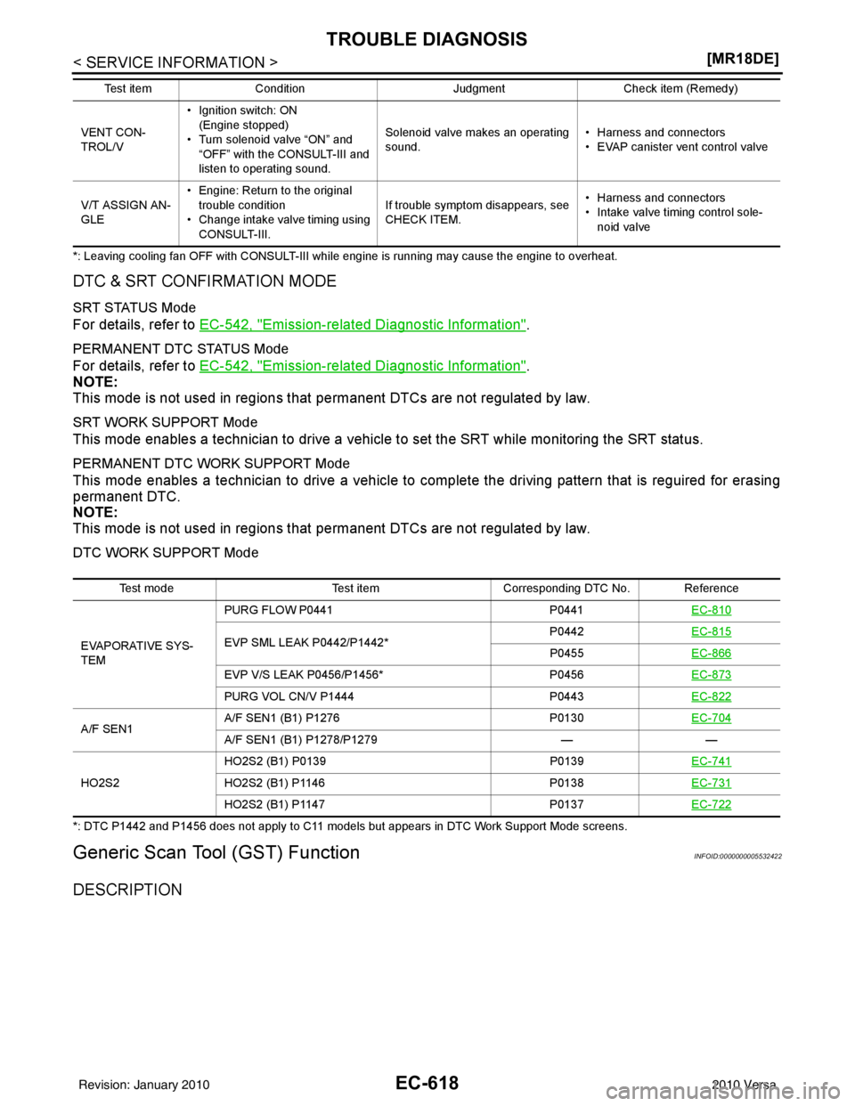
DTC WORK SUPPORT Mode
*: DTC P1442 and P1456 does not apply to C11 models but appears in DTC Work Support Mode screens.
Generic Scan Tool (GST) FunctionINFOID:0000000005532422
DESCRIPTION
VENT CON-
TROL/V• Ignition switch: ON
(Engine stopped)
• Turn solenoid valve “ON” and “OFF” with the CONSULT-III and
listen to operating sound. Solenoid valve makes an operating
sound.
• Harness and connectors
• EVAP canister vent control valve
V/T ASSIGN AN-
GLE • Engine: Return to the original
trouble condition
• Change intake valve timing using CONSULT-III. If trouble symptom disappears, see
CHECK ITEM.
• Harness and connectors
• Intake valve timing control sole-
noid valve
Test item
Condition JudgmentCheck item (Remedy)
Test mode Test itemCorresponding DTC No. Reference
EVAPORATIVE SYS-
TEM PURG FLOW P0441
P0441EC-810
EVP SML LEAK P0442/P1442* P0442
EC-815P0455EC-866
EVP V/S LEAK P0456/P1456* P0456EC-873
PURG VOL CN/V P1444 P0443EC-822
A/F SEN1 A/F SEN1 (B1) P1276
P0130EC-704A/F SEN1 (B1) P1278/P1279 ——
HO2S2 HO2S2 (B1) P0139
P0139EC-741
HO2S2 (B1) P1146 P0138EC-731
HO2S2 (B1) P1147 P0137EC-722
Revision: January 20102010 Versa
Page 1887 of 3745
EC-622
< SERVICE INFORMATION >[MR18DE]
TROUBLE DIAGNOSIS
MASS AIRFLOW• Engine: After warming up
• Air conditioner switch: OFF
• Shift lever: P or N (A/T, CVT),
Neutral (M/T)
•No load Idle
1.0 - 4.0 g·m/s
2,500 rpm 2.0 - 10.0 g·m/s
PURG VOL C/V • Engine: After warming up
• Air conditioner switch: OFF
• Shift lever: P or N (A/T, CVT),
Neutral (M/T)
•No load Idle
(Accelerator pedal is not depressed
even slightly, after engine starting)
0%
2,000 rpm 0 - 50%
INT/V TIM (B1) • Engine: After warming up
• Air conditioner switch: OFF
• Shift lever: P or N (A/T, CVT),
Neutral (M/T)
•No load Idle
−5 ° - 5 °CA
When revving engine up to 2,000 rpm
quickly Approx. 0
° - 40 °CA
INT/V SOL (B1) • Engine: After warming up
• Air conditioner switch: OFF
• Shift lever: P or N (A/T, CVT),
Neutral (M/T)
•No load Idle
0% - 2%
When revving engine up to 2,000 rpm
quickly Approx. 0% - 90%
AIR COND RLY • Engine: After warming up, idle the
engine Air conditioner switch: OFF
OFF
Air conditioner switch: ON
(Compressor operates) ON
FUEL PUMP RLY • For 1 second after turning ignition switch ON
• Engine running or cranking
ON
• Except above conditions OFF
VENT CONT/V • Ignition switch: ON OFF
THRTL RELAY • Ignition switch: ON ON
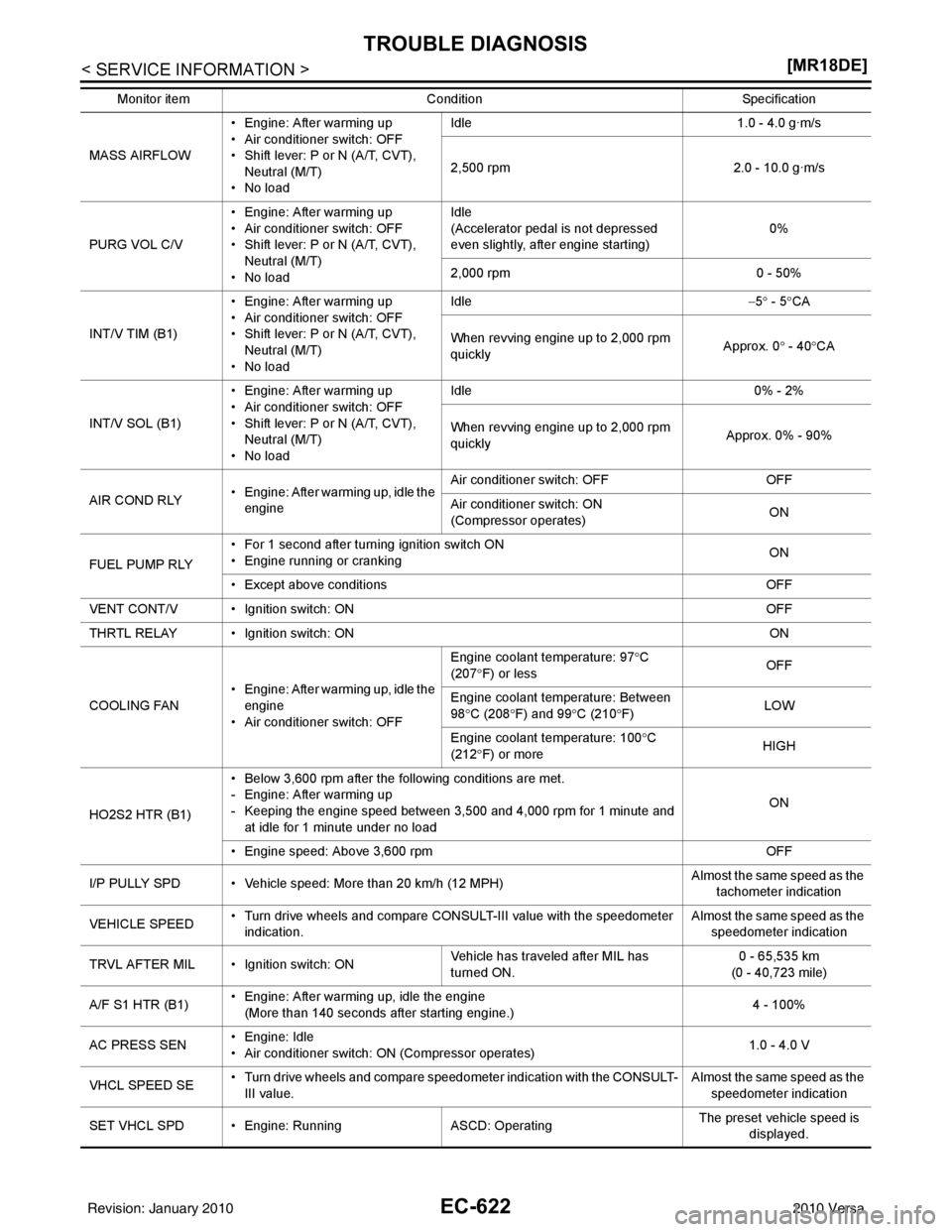
COOLING FAN • Engine: After warming up, idle the
engine
• Air conditioner switch: OFF Engine coolant temperature: 97
°C
(207 °F) or less OFF
Engine coolant temperature: Between
98 °C (208 °F) and 99 °C (210 °F) LOW
Engine coolant temperature: 100 °C
(212 °F) or more HIGH
HO2S2 HTR (B1) • Below 3,600 rpm after the following conditions are met.
- Engine: After warming up
- Keeping the engine speed between 3,500 and 4,000 rpm for 1 minute and
at idle for 1 minute under no load ON
• Engine speed: Above 3,600 rpm OFF
I/P PULLY SPD • Vehicle speed: More than 20 km/h (12 MPH) Almost the same speed as the
tachometer indication
VEHICLE SPEED • Turn drive wheels and compare CONSULT-III value with the speedometer
indication. Alm
os
t the same speed as the
speedometer indication
TRVL AFTER MIL • Ignition switch: ON Vehicle has traveled after MIL has
turned ON.0 - 65,535 km
(0 - 40,723 mile)
A/F S1 HTR (B1) • Engine: After warming up, idle the engine
(More than 140 seconds after starting engine.) 4 - 100%
AC PRESS SEN • Engine: Idle
• Air conditioner switch: ON (Compressor operates) 1.0 - 4.0 V
VHCL SPEED SE • Turn drive wheels and compare speedometer indication with the CONSULT-
III value. Almost the same speed as the
speedometer indication
SET VHCL SPD • Engine: Ru nningASCD: Operating The preset vehicle speed is
displayed.
Monitor item
Condition Specification
Revision: January 20102010 Versa
Page 1952 of 3745
DTC P0117, P0118 ECT SENSOREC-687
< SERVICE INFORMATION > [MR18DE]
C
D
E
F
G H
I
J
K L
M A
EC
NP
O
DTC Confirmation ProcedureINFOID:0000000005532511
NOTE:
If DTC Confirmation Procedure has been previously conducted, always turn ignition switch OFF and wait at
least 10 seconds before conducting the next test.
WITH CONSULT-III
1. Turn ignition switch ON and wait at least 5 seconds.
2. Check DTC.
3. If DTC is detected, go to EC-688, "
Diagnosis Procedure".
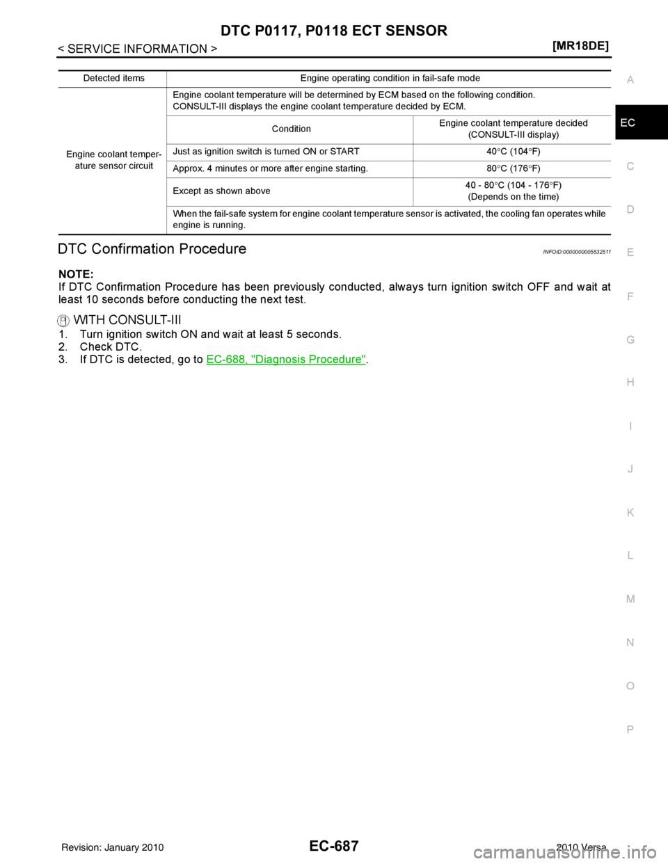
Detected items
Engine operating condition in fail-safe mode
Engine coolant temper- ature sensor circuit Engine coolant temperature will be determined by ECM based on the following condition.
CONSULT-III displays the engine coolant temperature decided by ECM.
Condition Engine coolant temperature decided
(CONSULT-III display)
Just as ignition switch is turned ON or START 40°C (104 °F)
Approx. 4 minutes or more after engine starting. 80°C (176 °F)
Except as shown above 40 - 80°
C (104 - 176 °F)
(Depends on the time)
When the fail-safe system for engine coolant temperature sensor is activated, the cooling fan operates while
engine is running.
Revision: January 20102010 Versa
Page 2152 of 3745
DTC P0500 VSSEC-887
< SERVICE INFORMATION > [MR18DE]
C
D
E
F
G H
I
J
K L
M A
EC
NP
O
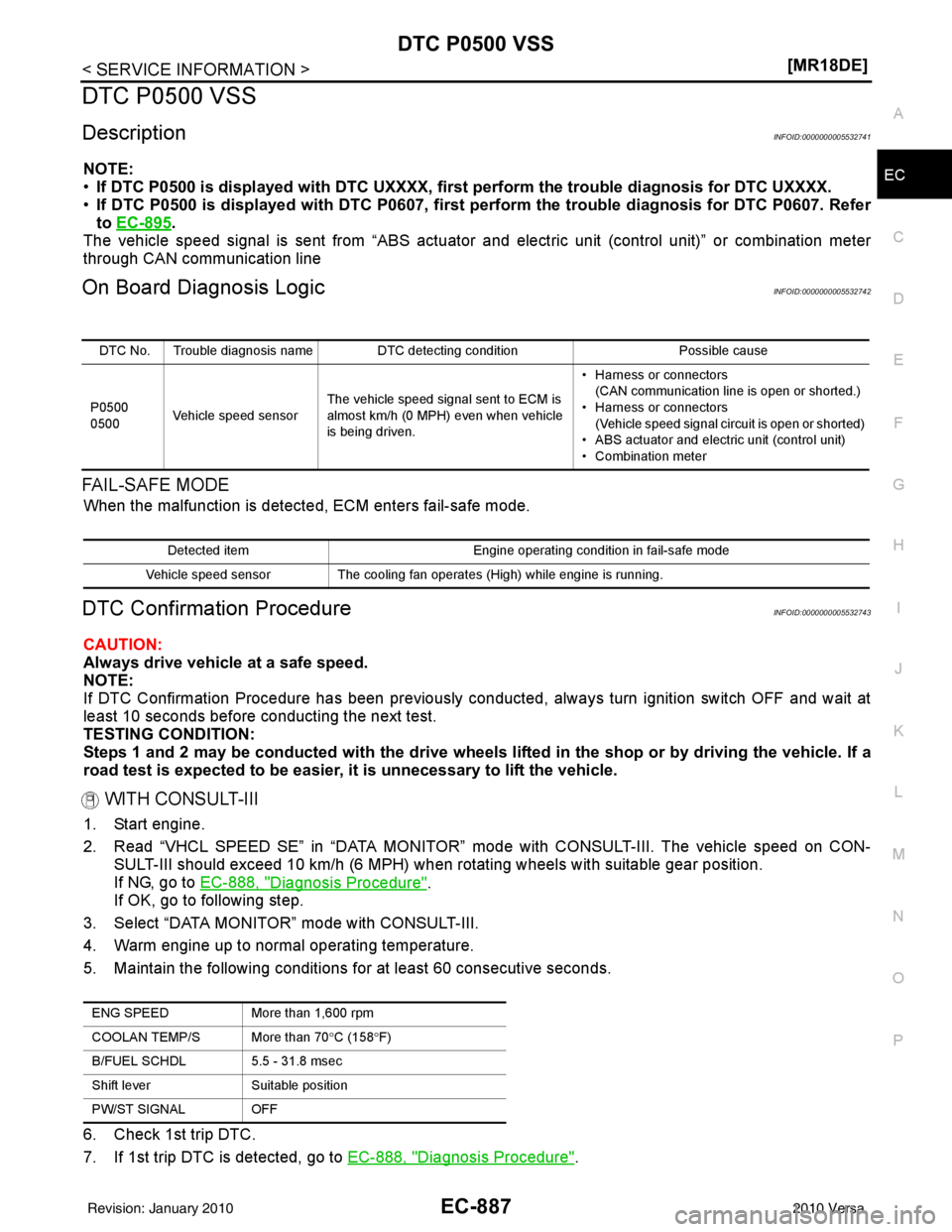
DTC P0500 VSS
DescriptionINFOID:0000000005532741
NOTE:
•
If DTC P0500 is displayed with DTC UXXXX, first perform the tr ouble diagnosis for DTC UXXXX.
• If DTC P0500 is displayed with DT C P0607, first perform the trouble diagnosis for DTC P0607. Refer
to EC-895
.
The vehicle speed signal is sent from “ABS actuator and electric unit (control unit)” or combination meter
through CAN communication line
On Board Diagnosis LogicINFOID:0000000005532742
FA I L - S A F E M O D E
When the malfunction is detect ed, ECM enters fail-safe mode.
DTC Confirmation ProcedureINFOID:0000000005532743
CAUTION:
Always drive vehicle at a safe speed.
NOTE:
If DTC Confirmation Procedure has been previously conducted, always turn ignition switch OFF and wait at
least 10 seconds before conducting the next test.
TESTING CONDITION:
Steps 1 and 2 may be conducted with the drive wheels li fted in the shop or by driving the vehicle. If a
road test is expected to be easier, it is unnecessary to lift the vehicle.
WITH CONSULT-III
1. Start engine.
2. Read “VHCL SPEED SE” in “DATA MONITOR” m ode with CONSULT-III. The vehicle speed on CON-
SULT-III should exceed 10 km/h (6 MPH) when rotating wheels with suitable gear position.
If NG, go to EC-888, "
Diagnosis Procedure".
If OK, go to following step.
3. Select “DATA MONITOR” mode with CONSULT-III.
4. Warm engine up to normal operating temperature.
5. Maintain the following conditions for at least 60 consecutive seconds.
6. Check 1st trip DTC.
7. If 1st trip DTC is detected, go to EC-888, "
Diagnosis Procedure".
DTC No. Trouble diagnosis name DTC detecting condition Possible cause
P0500
0500 Vehicle speed sensor The vehicle speed signal sent to ECM is
almost km/h (0 MPH) even when vehicle
is being driven. • Harness or connectors
(CAN communication line is open or shorted.)
• Harness or connectors (Vehicle speed signal circuit is open or shorted)
• ABS actuator and electric unit (control unit)
• Combination meter
Detected item Engine operating condition in fail-safe mode
Vehicle speed sensor The cooling fan operates (High) while engine is running.
ENG SPEEDMore than 1,600 rpm
COOLAN TEMP/S More than 70° C (158°F)
B/FUEL SCHDL 5.5 - 31.8 msec
Shift lever Suitable position
PW/ST SIGNAL OFF
Revision: January 20102010 Versa
Page 2154 of 3745
DTC P0506 ISC SYSTEMEC-889
< SERVICE INFORMATION > [MR18DE]
C
D
E
F
G H
I
J
K L
M A
EC
NP
O
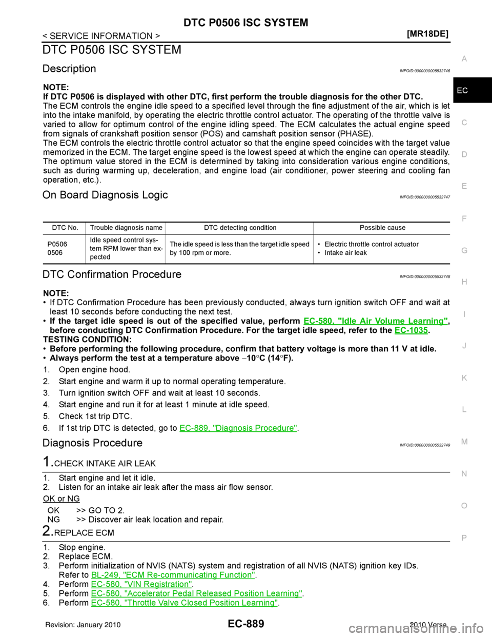
DTC P0506 ISC SYSTEM
DescriptionINFOID:0000000005532746
NOTE:
If DTC P0506 is displayed with ot
her DTC, first perform the trouble diagnosis for the other DTC.
The ECM controls the engine idle speed to a specified level through the fine adjustment of the air, which is let
into the intake manifold, by operating the electric thrott le control actuator. The operating of the throttle valve is
varied to allow for optimum control of the engine id ling speed. The ECM calculates the actual engine speed
from signals of crankshaft position sensor (POS) and camshaft position sensor (PHASE).
The ECM controls the electric throttle control actuator so that the engine speed coincides with the target value
memorized in the ECM. The target engine speed is the lowest speed at which the engine can operate steadily.
The optimum value stored in the ECM is determined by taking into consideration various engine conditions,
such as during warming up, deceleration, and engine load (air conditioner, power steering and cooling fan
operation, etc.).
On Board Diagnosis LogicINFOID:0000000005532747
DTC Confirmation ProcedureINFOID:0000000005532748
NOTE:
• If DTC Confirmation Procedure has been previously conduc ted, always turn ignition switch OFF and wait at
least 10 seconds before conducting the next test.
• If the target idle speed is ou t of the specified value, perform EC-580, "
Idle Air Volume Learning",
before conducting DTC Confirmation Procedure. For the target idle speed, refer to the EC-1035
.
TESTING CONDITION:
• Before performing the following procedure, confirm that battery voltage is more than 11 V at idle.
• Always perform the test at a temperature above −10° C (14° F).
1. Open engine hood.
2. Start engine and warm it up to normal operating temperature.
3. Turn ignition switch OFF and wait at least 10 seconds.
4. Start engine and run it for at least 1 minute at idle speed.
5. Check 1st trip DTC.
6. If 1st trip DTC is detected, go to EC-889, "
Diagnosis Procedure".
Diagnosis ProcedureINFOID:0000000005532749
1.CHECK INTAKE AIR LEAK
1. Start engine and let it idle.
2. Listen for an intake air leak after the mass air flow sensor.
OK or NG
OK >> GO TO 2.
NG >> Discover air leak location and repair.
2.REPLACE ECM
1. Stop engine.
2. Replace ECM.
3. Perform initialization of NVIS (NATS) system and registration of all NVIS (NATS) ignition key IDs.
Refer to BL-249, "
ECM Re-communicating Function".
4. Perform EC-580, "
VIN Registration".
5. Perform EC-580, "
Accelerator Pedal Released Position Learning".
6. Perform EC-580, "
Throttle Valve Closed Position Learning".
DTC No. Trouble diagnosis name DTC detecting condition Possible cause
P0506
0506 Idle speed control sys-
tem RPM lower than ex-
pected The idle speed is less than the target idle speed
by 100 rpm or more.
• Electric throttle control actuator
• Intake air leak
Revision: January 20102010 Versa
Page 2156 of 3745
DTC P0507 ISC SYSTEMEC-891
< SERVICE INFORMATION > [MR18DE]
C
D
E
F
G H
I
J
K L
M A
EC
NP
O
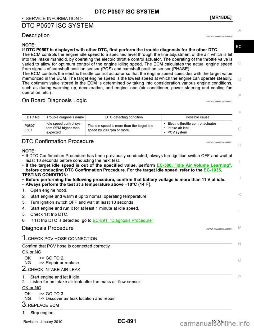
DTC P0507 ISC SYSTEM
DescriptionINFOID:0000000005532750
NOTE:
If DTC P0507 is displayed with ot
her DTC, first perform the trouble diagnosis for the other DTC.
The ECM controls the engine idle speed to a specified level through the fine adjustment of the air, which is let
into the intake manifold, by operating the electric thrott le control actuator. The operating of the throttle valve is
varied to allow for optimum control of the engine id ling speed. The ECM calculates the actual engine speed
from signals of camshaft position sensor (POS) and camshaft position sensor (PHASE).
The ECM controls the electric throttle control actuator so that the engine speed coincides with the target value
memorized in the ECM. The target engine speed is the lowest speed at which the engine can operate steadily.
The optimum value stored in the ECM is determined by taking into consideration various engine conditions,
such as during warming up, deceleration, and engine load (air conditioner, power steering and cooling fan
operation, etc.).
On Board Diagnosis LogicINFOID:0000000005532751
DTC Confirmation ProcedureINFOID:0000000005532752
NOTE:
• If DTC Confirmation Procedure has been previously conduc ted, always turn ignition switch OFF and wait at
least 10 seconds before conducting the next test.
• If the target idle speed is ou t of the specified value, perform EC-580, "
Idle Air Volume Learning",
before conducting DTC Confirmation Procedure. For the target idle speed, refer to the EC-1035
.
TESTING CONDITION:
• Before performing the following procedure, confirm that battery voltage is more than 11 V at idle.
• Always perform the test at a temperature above −10° C (14° F).
1. Open engine hood.
2. Start engine and warm it up to normal operating temperature.
3. Turn ignition switch OFF and wait at least 10 seconds.
4. Start engine and run it for at least 1 minute at idle speed.
5. Check 1st trip DTC.
6. If 1st trip DTC is detected, go to EC-891, "
Diagnosis Procedure".
Diagnosis ProcedureINFOID:0000000005532753
1.CHECK PCV HOSE CONNECTION
Confirm that PCV hose is connected correctly.
OK or NG
OK >> GO TO 2.
NG >> Repair or replace.
2.CHECK INTAKE AIR LEAK
1. Start engine and let it idle.
2. Listen for an intake air leak after the mass air flow sensor.
OK or NG
OK >> GO TO 3.
NG >> Discover air leak location and repair.
3.REPLACE ECM
1. Stop engine.
DTC No. Trouble diagnosis name DTC detecting condition Possible cause
P0507
0507 Idle speed control sys-
tem RPM higher than
expected The idle speed is more than the target idle
speed by 200 rpm or more. • Electric throttle control actuator
• Intake air leak
• PCV system
Revision: January 20102010 Versa
Page 2175 of 3745
EC-910
< SERVICE INFORMATION >[MR18DE]
DTC P1217 ENGINE OVER TEMPERATURE
DTC P1217 ENGINE OVER TEMPERATURE
System DescriptionINFOID:0000000005532774
SYSTEM DESCRIPTION
NOTE:
•
If DTC P1217 is displayed with DTC UXXXX, first perform the trouble diagnosis for DTC UXXXX.
• If DTC P1217 is displayed with DTC P0607, first perform the trouble diagno sis for DTC P0607. Refer
to EC-895
.
Cooling Fan Control
*1: The ECM determines the start signal status by the signals of engine speed and battery voltage.
*2: This signal is sent to ECM through CAN communication line.
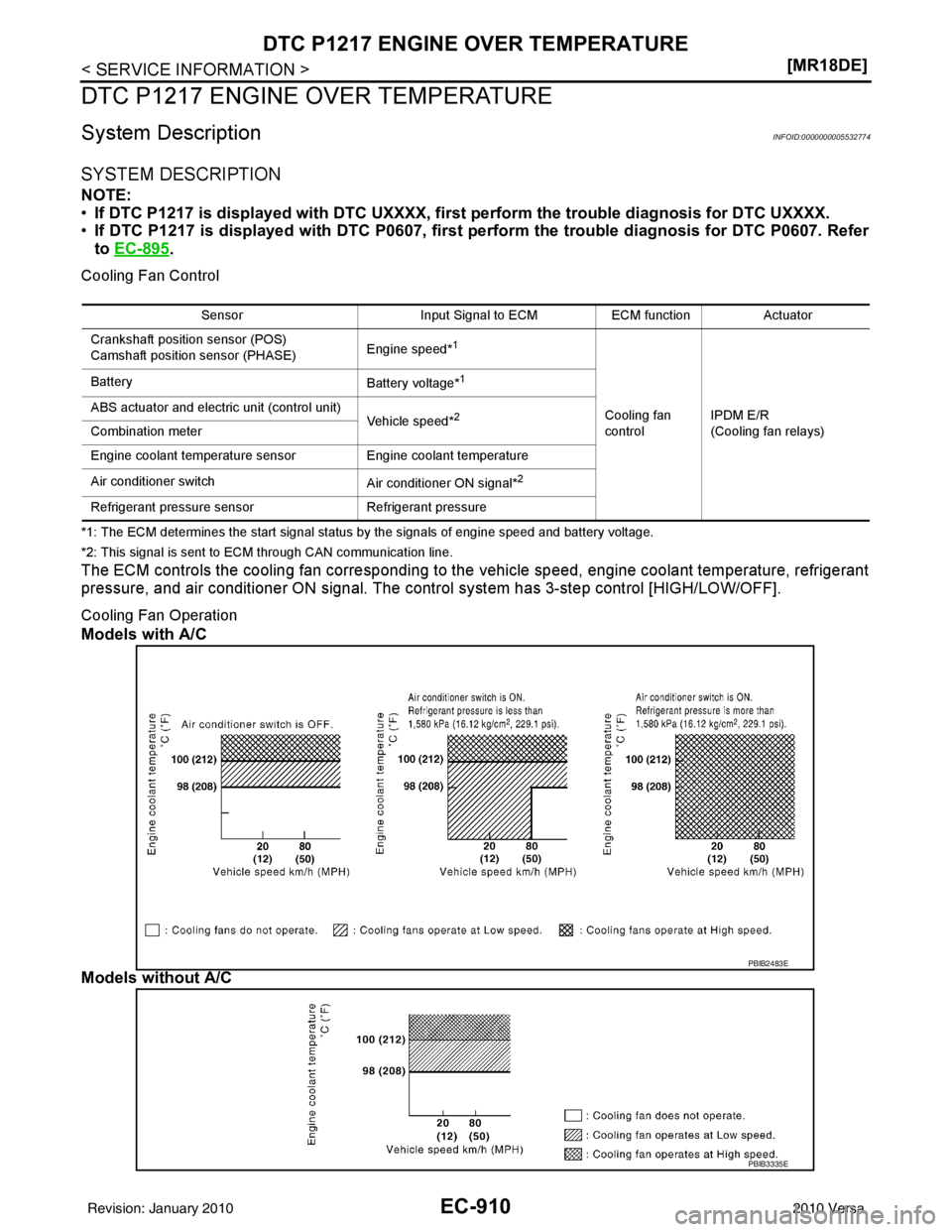
The ECM controls the cooling fan corresponding to the vehicle speed, engine coolant temperature, refrigerant
pressure, and air conditioner ON signal. The contro l system has 3-step control [HIGH/LOW/OFF].
Cooling Fan Operation
Models with A/C
Models without A/C
Sensor Input Signal to ECMECM functionActuator
Crankshaft position sensor (POS)
Camshaft position sensor (PHASE) Engine speed*
1
Cooling fan
controlIPDM E/R
(Cooling fan relays)
Battery
Battery voltage*
1
ABS actuator and electric unit (control unit)
Vehicle speed*2
Combination meter
Engine coolant temperature sensor Engine coolant temperature
Air conditioner switch Air conditioner ON signal*
2
Refrigerant pressure sensorRefrigerant pressure
PBIB2483E
PBIB3335E
Revision: January 20102010 Versa
Page 2176 of 3745
DTC P1217 ENGINE OVER TEMPERATUREEC-911
< SERVICE INFORMATION > [MR18DE]
C
D
E
F
G H
I
J
K L
M A
EC
NP
O
Cooling Fan Relay Operation
The ECM controls cooling fan relays in the IPDM E/R through CAN communication line.
CONSULT-III Reference Val
ue in Data Monitor ModeINFOID:0000000005532775
Specification data are reference values.
On Board Diagnosis LogicINFOID:0000000005532776
If the cooling fan or another component in the cooli ng system malfunctions, engine coolant temperature will
rise. When the engine coolant temperature reaches an abnormally high temperature condition, a malfunction
is indicated.
This self-diagnosis has the on e trip detection logic.
CAUTION:
When a malfunction is in dicated, be sure to replace the coolant. Refer to CO-36, "
Changing Engine
Coolant". Also, replace the engine oil. Refer to LU-18, "Changing Engine Oil".
1. Fill radiator with coolant up to specified level with a filling speed of 2 liters per minute. Be sure to
use coolant with the proper mixture ratio. Refer to MA-15, "
Anti-freeze Coolant Mixture Ratio".
2. After refilling coolant, run engine to ensure that no water-flow noise is emitted.
Overall Function CheckINFOID:0000000005532777
Use this procedure to check the overall function of the cooling fan. During this check, a DTC might not be con-
firmed.
WARNING:
Cooling fan speed Cooling fan relay
123
Stop (OFF) OFFOFFOFF
Low (LOW) ONOFF OFF
High (HI) ONONON
Monitor item Condition Specification
AIR COND SIG • Engine: After warming up, idle
the engine Air conditioner switch: OFF
OFF
Air conditioner switch: ON
(Compressor operates.) ON
COOLING FAN • Engine: After warming up, idle
the engine
• Air conditioner switch: OFF Engine coolant temperature: 97
°C
(207 °F) or less OFF
Engine coolant temperature: Between
98 °C (208 °F) and 99° C (210°F) LOW
Engine coolant temperature: 100 °C
(212 °F) or more HIGH
DTC No. Trouble diagnosis name
DTC detecting conditionPossible cause
P1217
1217 Engine over temperature
(Overheat) • Cooling fan does not operate properly (Over-
heat).
• Cooling fan system does not operate properly (Overheat).
• Engine coolant was not added to the system using the proper filling method.
• Engine coolant is not within the specified
range. • Harness or connectors
(Cooling fan circuit is open or shorted.)
• Cooling fan
• IPDM E/R (Cooling fan relays)
•Radiator hose
•Radiator
• Reservoir tank
•Radiator cap
• Water pump
•Thermostat
• Water control valve
For more information, refer to EC-917,
"Main 13 Causes of Overheating".
Revision: January 20102010 Versa