engine overheat NISSAN TIIDA 2011 Service User Guide
[x] Cancel search | Manufacturer: NISSAN, Model Year: 2011, Model line: TIIDA, Model: NISSAN TIIDA 2011Pages: 3787, PDF Size: 78.35 MB
Page 1473 of 3787
P0125 ECT SENSOREC-179
< COMPONENT DIAGNOSIS > [HR16DE]
C
D
E
F
G H
I
J
K L
M A
EC
NP
O
2. Select “DATA MONITOR” mode with CONSULT-III.
3. Check that “COOLAN TEMP/S” is above 10
°C (50° F).
With GST
Follow the procedure “With CONSULT-III” above.
Is it above 10
°C (50°F)?
YES >> INSPECTION END
NO >> GO TO 3.
3.PERFORM DTC CONFIRMATION PROCEDURE
With CONSULT-III
1. Start engine and run it for 65 minutes at idle speed.
2. Check 1st tip DTC.
If “COOLAN TEMP/S” indicatio n increases to more than 10°C (50 °F) within 65 minutes, stop engine
because the test resu lt will be OK.
CAUTION:
Be careful not to overheat engine.
With GST
Follow the procedure “With CONSULT-III” above.
Is 1st trip DTC detected?
YES >> EC-179, "Diagnosis Procedure"
NO >> INSPECTION END
Diagnosis ProcedureINFOID:0000000005929866
1.CHECK GROUND CONNECTION
1. Turn ignition switch OFF.
2. Check ground connections E15, E24. Refer to EC-127, "
Ground Inspection".
Is the inspection result normal?
YES >> GO TO 2.
NO >> Repair or replace ground connection.
2.CHECK ENGINE COOLANT TEMPERATURE SENSOR
Refer to EC-179, "
Component Inspection".
Is the inspection result normal?
YES >> GO TO 3.
NO >> Replace engine coolant temperature sensor. Refer to CO-24, "
Exploded View".
3.CHECK THERMOSTAT OPERATION
When the engine is cold [lower than 70 °C (158° F)] condition, grasp lower radiator hose and confirm the engine
coolant does not flow.
Is the inspection result normal?
YES >> GO TO 4.
NO >> Repair or replace thermostat. Refer to CO-22, "
Removal and Installation".
4.CHECK INTERMITTENT INCIDENT
Refer to EC-122, "
Diagnosis Procedure".
>> INSPECTION END
Component InspectionINFOID:0000000006141196
1.CHECK ENGINE COOLANT TEMPERATURE SENSOR
1. Turn ignition switch OFF.
2. Disconnect engine coolant temperature sensor harness connector.
3. Remove engine coolant temperature sensor.
Revision: May 2010 2011 Versa
Page 1551 of 3787
P0300, P0301, P0302, P0303, P0304 MISFIRE
EC-257
< COMPONENT DIAGNOSIS > [HR16DE]
C
D
E
F
G H
I
J
K L
M A
EC
NP
O
P0300, P0301, P0302, P0303, P0304 MISFIRE
DTC LogicINFOID:0000000005929932
DTC DETECTION LOGIC
When a misfire occurs, engine speed will fluctuate. If the engine speed fluctuates
enough to cause the crank-
shaft position (CKP) sensor (POS) signal to vary, ECM can determine that a misfire is occurring.
The misfire detection logic consists of the following two conditions.
1. One Trip Detection Logic (Three Way Catalyst Damage)
On the 1st trip, when a misfire condition occurs that can damage the three way catalyst (TWC) due to
overheating, the MIL will blink.
When a misfire condition occurs, the ECM monitors the CKP sensor signal every 200 engine revolutions
for a change.
When the misfire condition decreases to a level t hat will not damage the TWC, the MIL will turn off.
If another misfire condition occurs that can damage the TWC on a second trip, the MIL will blink.
When the misfire condition decreases to a level t hat will not damage the TWC, the MIL will remain on.
If another misfire condition occurs that can damage the TWC, the MIL will begin to blink again.
2. Two Trip Detection Logic (Exhaust quality deterioration) For misfire conditions that will not damage the TWC (but will affect vehicle emissions), the MIL will only
light when the misfire is detected on a second trip. Du ring this condition, the ECM monitors the CKP sen-
sor signal every 1,000 engine revolutions.
A misfire malfunction can be detected on any one cylinder or on multiple cylinders.
DTC CONFIRMATION PROCEDURE
1.PRECONDITIONING
If DTC Confirmation Procedure has been previously conducted, always turn ignition switch OFF and wait at
least 10 seconds before conducting the next test.
>> GO TO 2.
2.PERFORM DTC CONFIRMATION PROCEDURE-I
1. Start engine and warm it up to normal operating temperature.
2. Turn ignition switch OFF and wait at least 10 seconds.
3. Restart engine and let it idle for about 15 minutes.
4. Check 1st trip DTC.
Is 1st trip DTC detected?
YES >> Go to EC-258, "Diagnosis Procedure".
NO >> GO TO 3.
3.PERFORM DTC CONFIRMATION PROCEDURE-II
1. Turn ignition switch OFF and wait at least 10 seconds.
Sensor Input signal to ECM ECM function
Crankshaft position sensor (POS) Engine speedOn board diagnosis of misfire
DTC No. Trouble diagnosis name DTC detecting condition Possible cause
P0300 Multiple cylinder misfire detected Multiple cylinders misfire. • Improper spark plug • Insufficient compression
• Incorrect fuel pressure
• The fuel injector circuit is open or shorted
• Fuel injector
• Intake air leak
• The ignition signal circuit is open or shorted
• Lack of fuel
• Signal plate
• A/F sensor 1
• Incorrect PCV hose connection
P0301 No.1 cylinder misfire detected No. 1 cylinder misfires.
P0302 No. 2 cylinder misfire detected No. 2 cylinder misfires.
P0303 No. 3 cylinder misfire detected No. 3 cylinder misfires.
P0304 No. 4 cylinder misfire detected No. 4 cylinder misfires.
Revision: May 2010
2011 Versa
Page 1666 of 3787
EC-372
< COMPONENT DIAGNOSIS >[HR16DE]
P1217 ENGINE OVER TEMPERATURE
P1217 ENGINE OVER TEMPERATURE
DTC LogicINFOID:0000000005930041
DTC DETECTION LOGIC
NOTE:
•
If DTC P1217 is displayed with DTC UXXXX, first perform the trouble diagnosis for DTC UXXXX.
• If DTC P1217 is displayed with DTC P0607, first perform the trouble diagno sis for DTC P0607. Refer
to EC-361, "
DTC Logic".
If the cooling fan or another component in the cooling system malfunctions, engine coolant temperature will
rise.
When the engine coolant temperature reaches an abnorma lly high temperature condition, a malfunction is
indicated.
CAUTION:
When a malfunction is indicated, be sure to replace the coolant. Refer to CO-11, "
Changing Engine
Coolant". Also, replace the engine oil. Refer to LU-8, "Draining" and LU-8, "Refilling".
1. Fill radiator with coolant up to specified level with a filling speed of 2 liters per minute. Be sure to use coolant with the proper mixture ratio. Refer to MA-15, "
Anti-freeze Coolant Mixture Ratio".
2. After refilling coolant, run engine to en sure that no water-flow noise is emitted.
DTC CONFIRMATION PROCEDURE
1.PERFORM COMPONENT FUNCTION CHECK
Perform component function check. Refer to EC-372, "
Component Function Check".
NOTE:
Use component function check to check the overall function of the cooling fan. During this check, a DTC might
not be confirmed.
Is the inspection result normal?
YES >> INSPECTION END
NO >> Go to EC-373, "
Diagnosis Procedure".
Component Function CheckINFOID:0000000005930042
1.PERFORM COMPONENT FUNCTION CHECK-I
WARNING:
Never remove the radiator cap when the engine is hot. Serious burns could be caused by high pres-
sure fluid escaping from the radiator.
Wrap a thick cloth around cap. Carefully remove the cap by turning it a quarter turn to allow built-up
pressure to escape. Then turn the cap all the way off.
DTC No. Trouble diagnosis name DTC detecting conditionPossible cause
P1217 Engine over temperature
(Overheat) • Cooling fan does not operate properly (Over-
heat).
• Cooling fan system does not operate properly (Overheat).
• Engine coolant was not added to the system using the proper filling method.
• Engine coolant is not within the specified range. • Harness or connectors
(The cooling fan circuit is open or
shorted.)
• IPDM E/R (Cooling fan relay-1)
• Cooling fan relays-2 and -3
• Cooling fan motor
•Radiator hose
•Radiator
•Radiator cap
• Reservoir tank
• Water pump
•Thermostat
• Water control valve
Revision: May 2010 2011 Versa
Page 1772 of 3787
EC-478
< ECU DIAGNOSIS >[HR16DE]
ECM
DTC Index
INFOID:0000000005930154
× :Applicable —: Not applicable
2 • P0031 P0032 Air fuel ratio (A/F) sensor 1 heater
• P0037 P0038 Heated oxygen sensor 2 heater
• P0075 Intake valve timing control solenoid valve
• P0130 P0131 P0132 P0133 P2A00 Air fuel ratio (A/F) sensor 1
• P0137 P0138 P0139 Heated oxygen sensor 2
• P0441 EVAP control system purge flow monitoring
• P0443 P0444 P0445 EVAP canister purge volume control solenoid valve
• P0447 P0448 EVAP canister vent control valve
• P0451 P0452 P0453 EVAP control system pressure sensor
• P0603 ECM power supply
• P0710 P0720 P0725 P0731 P0732 P0733 P0734 P0740 P0744 P0745 P0750 P0755 P1705 P1760 A/T related sensors,
solenoid valves and switches
• P1217 Engine over temperature (OVERHEAT)
• P1805 Brake switch
• P2100 P2103 Throttle control motor relay
• P2101 Electric throttle control function
• P2118 Throttle control motor
3 • P0011 Intake valve timing control • P0171 P0172 Fuel injection system function
• P0300 - P0304 Misfire
• P0420 Three way catalyst function
• P0442 P0456 EV AP control system (SMALL LEAK, VERY SMALL LEAK)
• P0455 EVAP control system (GROSS LEAK)
• P0506 P0507 Idle speed control system
• P1148 Closed loop control
• P1421 Cold start control
• P1715 Input speed sensor
• P2119 Electric throttle control actuator
Priority
Detected items (DTC)
DTC*1
Items
(CONSULT-III screen terms) SRT
code Trip MIL Permanent
DTC
group*
4
Reference page
CONSULT-III
GST*
2ECM*3
U0101 0101*5LOST COMM (TCM) — 1×BEC-128
U0140
0140*5LOST COMM (BCM) — 1×BEC-130
U1001
1001*5CAN COMM CIRCUIT — 2——EC-128
P0000 0000 NO DTC IS DETECTED.
FURTHER TESTING
MAY BE REQUIRED. ——
Flashing*8——
P0011 0011 INT/V TIM CONT-B1 ×2 ×BEC-134
P0031 0031 A/F SEN1 HTR (B1) — 2×BEC-138
P0032 0032 A/F SEN1 HTR (B1) — 2×BEC-138
P0037 0037 HO2S2 HTR (B1) — 2×BEC-142
P0038 0038 HO2S2 HTR (B1) — 2×BEC-142
P0075 0075 INT/V TIM V/CIR-B1 — 2×BEC-146
P0101 0101 MAF SEN/CIRCUIT-B1 — 2×BEC-150
P0102 0102 MAF SEN/CIRCUIT-B1 — 1×BEC-158
P0103 0103 MAF SEN/CIRCUIT-B1 — 1×BEC-158
P0112 0112 IAT SEN/CIRCUIT-B1 — 2×BEC-164
P0113 0113 IAT SEN/CIRCUIT-B1 — 2×BEC-164
P0116 0116 ECT SEN/CIRC — 2×BEC-168
P0117 0117 ECT SEN/CIRC — 1×BEC-170
Revision: May 2010 2011 Versa
Page 1782 of 3787
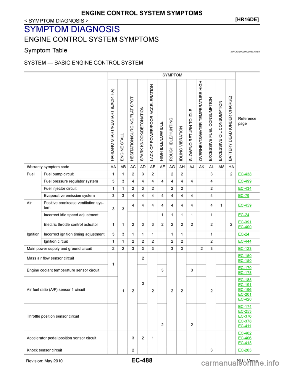
EC-488
< SYMPTOM DIAGNOSIS >[HR16DE]
ENGINE CONTROL SYSTEM SYMPTOMS
SYMPTOM DIAGNOSIS
ENGINE CONTROL SYSTEM SYMPTOMS
Symptom TableINFOID:0000000005930158
SYSTEM — BASIC ENGINE CONTROL SYSTEM
SYMPTOM
Reference
page
HARD/NO START/RESTART (EXCP. HA)
ENGINE STALL
HESITATION/SURGING/FLAT SPOT
SPARK KNOCK/DETONATION
LACK OF POWER/POOR ACCELERATION
HIGH IDLE/LOW IDLE
ROUGH IDLE/HUNTING
IDLING VIBRATION
SLOW/NO RETURN TO IDLE
OVERHEATS/WATER TEMPERATURE HIGH
EXCESSIVE FUEL CONSUMPTION
EXCESSIVE OIL CONSUMPTION
BATTERY DEAD (UNDER CHARGE)
Warranty symptom code AA AB AC AD AE AF AG AH AJ AK AL AM HA
Fuel Fuel pump circuit 11232 22 3 2EC-438
Fuel pressure regulator system 334444444 4 EC-499
Fuel injector circuit11232 22 2EC-434
Evaporative emission system 334444444 4 EC-79
Air Positive crankcase ventilation sys-
tem 334444444 41
EC-459
Incorrect idle speed adjustment 1 1 1 1 1EC-24
Electric throttle control actuator 112332222 2 2 EC-391EC-400
IgnitionIncorrect ignition timing adjustment33111 11
1EC-24
Ignition circuit 11222 22 2EC-444
Main power supply and ground circuit 22333 33 23 EC-123
Mass air flow sensor circuit
1
12 2
222 2 EC-150EC-150
Engine coolant temperature sensor circuit
333
EC-170EC-178
Air fuel ratio (A/F) sensor 1 circuit EC-185
EC-191
EC-196
EC-201
EC-420
Throttle position sensor circuit
22EC-174
EC-253
EC-376
EC-378
EC-411
Accelerator pedal position sensor circuit
3 2 1 EC-402EC-406
EC-415
Knock sensor circuit
23EC-263
Revision: May 2010 2011 Versa
Page 1783 of 3787
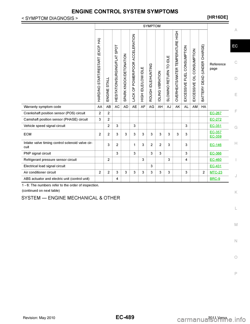
ENGINE CONTROL SYSTEM SYMPTOMSEC-489
< SYMPTOM DIAGNOSIS > [HR16DE]
C
D
E
F
G H
I
J
K L
M A
EC
NP
O
1 - 6: The numbers refer to the order of inspection.
(continued on next table)
SYSTEM — ENGINE MECHANICAL & OTHER
Crankshaft position sensor (POS) circuit 2 2
EC-267
Camshaft position sensor (PHASE) circuit 3 2EC-272
Vehicle speed signal circuit2 3 33EC-351
ECM 22333333333 EC-357EC-359
Intake valve timing control solenoid valve cir-
cuit32 13223 3
EC-146
PNP signal circuit3 3 3 33EC-366
Refrigerant pressure sensor circuit 233 4 EC-460
Electrical load signal circuit 3EC-431
Air conditioner circuit 223333333 3 2 MTC-23
ABS actuator and electric unit (control unit)4 BRC-9
SYMPTOM
Reference
page
HARD/NO START/RESTART (EXCP. HA)
ENGINE STALL
HESITATION/SURGING/FLAT SPOT
SPARK KNOCK/DETONATION
LACK OF POWER/POOR ACCELERATION
HIGH IDLE/LOW IDLE
ROUGH IDLE/HUNTING
IDLING VIBRATION
SLOW/NO RETURN TO IDLE
OVERHEATS/WATER TEMPERATURE HIGH
EXCESSIVE FUEL CONSUMPTION
EXCESSIVE OIL CONSUMPTION
BATTERY DEAD (UNDER CHARGE)
Warranty symptom code AA AB AC AD AE AF AG AH AJ AK AL AM HA
Revision: May 2010 2011 Versa
Page 1784 of 3787
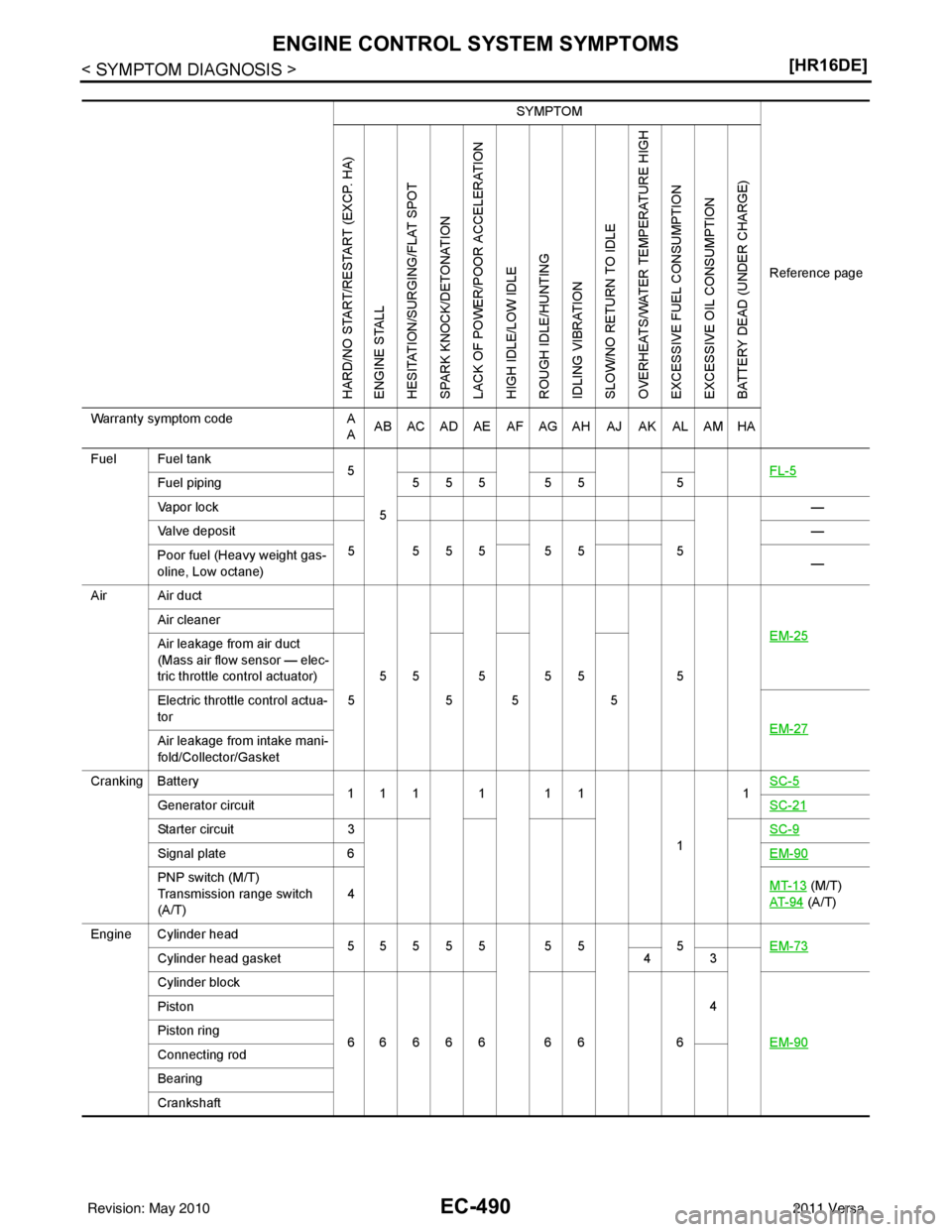
EC-490
< SYMPTOM DIAGNOSIS >[HR16DE]
ENGINE CONTROL SYSTEM SYMPTOMS
SYMPTOM
Reference page
HARD/NO START/RESTART (EXCP. HA)
ENGINE STALL
HESITATION/SURGING/FLAT SPOT
SPARK KNOCK/DETONATION
LACK OF POWER/POOR ACCELERATION
HIGH IDLE/LOW IDLE
ROUGH IDLE/HUNTING
IDLING VIBRATION
SLOW/NO RETURN TO IDLE
OVERHEATS/WATER TEMPERATURE HIGH
EXCESSIVE FUEL CONSUMPTION
EXCESSIVE OIL CONSUMPTION
BATTERY DEAD (UNDER CHARGE)
Warranty symptom code A
A AB AC AD AE AF AG AH AJ AK AL AM HA
Fuel Fuel tank 5
5 FL-5
Fuel piping
5 5 5 5 5 5
Va p o r l o c k —
Valve deposit 5 555 55 5—
Poor fuel (Heavy weight gas-
oline, Low octane) —
Air Air duct
55555 5 EM-25
Air cleaner
Air leakage from air duct
(Mass air flow sensor — elec-
tric throttle control actuator)
555 5
Electric throttle control actua-
tor
EM-27
Air leakage from intake mani-
fold/Collector/Gasket
Cranking Battery 111111
11
SC-5
Generator circuit
SC-21
Starter circuit3 SC-9
Signal plate6 EM-90
PNP switch (M/T)
Transmission range switch
(A/T)4
MT-13 (M/T)
AT- 9 4
(A/T)
Engine Cylinder head 55555 55 5 EM-73
Cylinder head gasket 4 3
Cylinder block
66666 66 64
EM-90
Piston
Piston ring
Connecting rod
Bearing
Crankshaft
Revision: May 2010 2011 Versa
Page 1785 of 3787
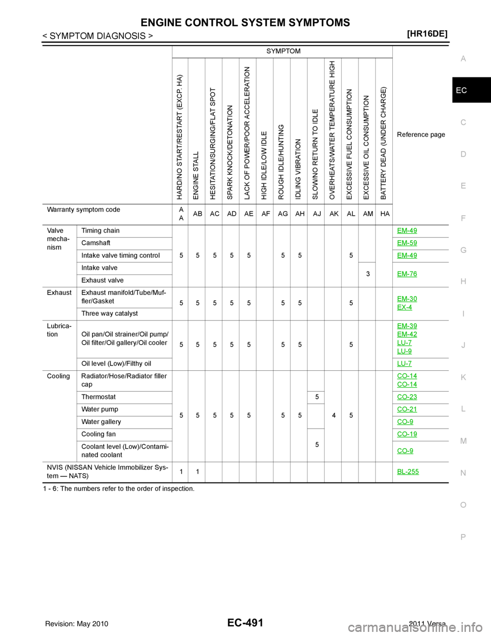
ENGINE CONTROL SYSTEM SYMPTOMSEC-491
< SYMPTOM DIAGNOSIS > [HR16DE]
C
D
E
F
G H
I
J
K L
M A
EC
NP
O
1 - 6: The numbers refer to the order of inspection. Va l v e
mecha-
nism
Timing chain
55555 55 5 EM-49
Camshaft
EM-59
Intake valve timing controlEM-49
Intake valve
3EM-76
Exhaust valve
Exhaust Exhaust manifold/Tube/Muf- fler/Gasket 55555 55 5 EM-30
EX-4Three way catalyst
Lubrica-
tion Oil pan/Oil strainer/Oil pump/ Oil filter/Oil gallery/Oil cooler 55555 55 5EM-39
EM-42
LU-7
LU-9
Oil level (Low)/Filthy oil
LU-7
Cooling Radiator/Hose/Radiator filler
cap
55555 55 45 CO-14
CO-14
Thermostat
5CO-23
Water pump CO-21
Water galleryCO-9
Cooling fan
5CO-19
Coolant level (Low)/Contami-
nated coolant
CO-9
NVIS (NISSAN Vehicle Immobilizer Sys-
tem — NATS)11
BL-255
SYMPTOM
Reference page
HARD/NO START/RESTART (EXCP. HA)
ENGINE STALL
HESITATION/SURGING/FLAT SPOT
SPARK KNOCK/DETONATION
LACK OF POWER/POOR ACCELERATION
HIGH IDLE/LOW IDLE
ROUGH IDLE/HUNTING
IDLING VIBRATION
SLOW/NO RETURN TO IDLE
OVERHEATS/WATER TEMPERATURE HIGH
EXCESSIVE FUEL CONSUMPTION
EXCESSIVE OIL CONSUMPTION
BATTERY DEAD (UNDER CHARGE)
Warranty symptom code A
A AB AC AD AE AF AG AH AJ AK AL AM HA
Revision: May 2010
2011 Versa
Page 1884 of 3787
EC-590
< SERVICE INFORMATION >[MR18DE]
TROUBLE DIAGNOSIS
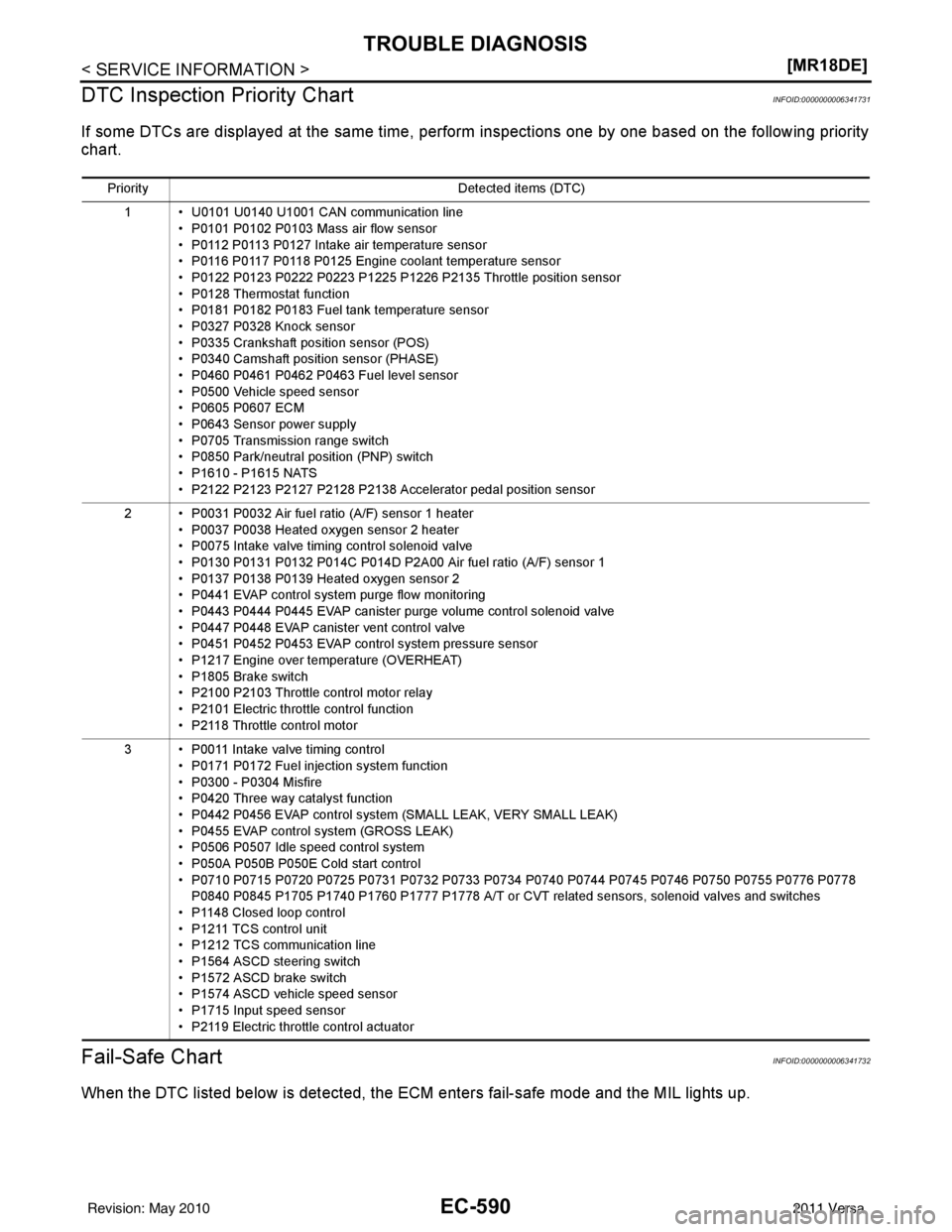
DTC Inspection Priority Chart
INFOID:0000000006341731
If some DTCs are displayed at the same time, perform inspections one by one based on the following priority
chart.
Fail-Safe ChartINFOID:0000000006341732
When the DTC listed below is detected, the ECM enters fail-safe mode and the MIL lights up.
Priority Detected items (DTC)
1 • U0101 U0140 U1001 CAN communication line • P0101 P0102 P0103 Mass air flow sensor
• P0112 P0113 P0127 Intake air temperature sensor
• P0116 P0117 P0118 P0125 Engine coolant temperature sensor
• P0122 P0123 P0222 P0223 P1225 P1226 P2135 Throttle position sensor
• P0128 Thermostat function
• P0181 P0182 P0183 Fuel tank temperature sensor
• P0327 P0328 Knock sensor
• P0335 Crankshaft position sensor (POS)
• P0340 Camshaft position sensor (PHASE)
• P0460 P0461 P0462 P0463 Fuel level sensor
• P0500 Vehicle speed sensor
• P0605 P0607 ECM
• P0643 Sensor power supply
• P0705 Transmission range switch
• P0850 Park/neutral position (PNP) switch
• P1610 - P1615 NATS
• P2122 P2123 P2127 P2128 P2138 Accelerator pedal position sensor
2 • P0031 P0032 Air fuel ratio (A/F) sensor 1 heater • P0037 P0038 Heated oxygen sensor 2 heater
• P0075 Intake valve timing control solenoid valve
• P0130 P0131 P0132 P014C P014D P2A00 Air fuel ratio (A/F) sensor 1
• P0137 P0138 P0139 Heated oxygen sensor 2
• P0441 EVAP control system purge flow monitoring
• P0443 P0444 P0445 EVAP canister purge volume control solenoid valve
• P0447 P0448 EVAP canister vent control valve
• P0451 P0452 P0453 EVAP control system pressure sensor
• P1217 Engine over temperature (OVERHEAT)
• P1805 Brake switch
• P2100 P2103 Throttle control motor relay
• P2101 Electric throttle control function
• P2118 Throttle control motor
3 • P0011 Intake valve timing control • P0171 P0172 Fuel injection system function
• P0300 - P0304 Misfire
• P0420 Three way catalyst function
• P0442 P0456 EVAP co ntrol system (SMALL LEAK, VERY SMALL LEAK)
• P0455 EVAP control system (GROSS LEAK)
• P0506 P0507 Idle speed control system
• P050A P050B P050E Cold start control
• P0710 P0715 P0720 P0725 P0731 P0732 P0733 P0734 P0740 P0744 P0745 P0746 P0750 P0755 P0776 P0778 P0840 P0845 P1705 P1740 P1760 P1777 P1778 A/T or CVT related sensors, solenoid valves and switches
• P1148 Closed loop control
• P1211 TCS control unit
• P1212 TCS communication line
• P1564 ASCD steering switch
• P1572 ASCD brake switch
• P1574 ASCD vehicle speed sensor
• P1715 Input speed sensor
• P2119 Electric throttle control actuator
Revision: May 2010 2011 Versa
Page 1886 of 3787
EC-592
< SERVICE INFORMATION >[MR18DE]
TROUBLE DIAGNOSIS
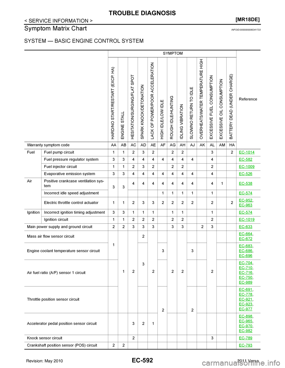
Symptom Matrix Chart
INFOID:0000000006341733
SYSTEM — BASIC ENGINE CONTROL SYSTEM
SYMPTOM
Reference
HARD/NO START/RESTART (EXCP. HA)
ENGINE STALL
HESITATION/SURGING/FLAT SPOT
SPARK KNOCK/DETONATION
LACK OF POWER/POOR ACCELERATION
HIGH IDLE/LOW IDLE
ROUGH IDLE/HUNTING
IDLING VIBRATION
SLOW/NO RETURN TO IDLE
OVERHEATS/WATER TEMPERATURE HIGH
EXCESSIVE FUEL CONSUMPTION
EXCESSIVE OIL CONSUMPTION
BATTERY DEAD (UNDER CHARGE)
Warranty symptom code AA AB AC AD AE AF AG AH AJ AK AL AM HA
Fuel Fuel pump circuit 11232 22 3 2EC-1014
Fuel pressure regulator system 334444444 4 EC-582
Fuel injector circuit11232 22 2EC-1009
Evaporative emission system 334444444 4 EC-526
Air Positive crankcase ventilation sys-
tem 334444444 41
EC-538
Incorrect idle speed adjustment 1 1 1 1 1EC-574
Electric throttle control actuator 112332222 2 2 EC-952,
EC-963
IgnitionIncorrect ignition timing adjustment33111 11 1EC-574
Ignition circuit 11222 22 2EC-1019
Main power supply and ground circuit 22333 33 23 EC-633
Mass air flow sensor circuit
1
12 2
222 2 EC-664,
EC-672
Engine coolant temperature sensor circuit
333
EC-683
,
EC-686
,
EC-696
Air fuel ratio (A/F) sensor 1 circuit EC-704
,
EC-710
,
EC-716
,
EC-750
,
EC-989
Throttle position sensor circuit
22EC-691
,
EC-778
,
EC-921
,
EC-923
,
EC-977
Accelerator pedal position sensor circuit 3 2 1 EC-898
,
EC-965
,
EC-970
,
EC-982
Knock sensor circuit 23EC-789
Crankshaft position sensor (POS) circuit 2 2 EC-793
Revision: May 20102011 Versa