NISSAN TITAN 2019 Owner´s Manual
TITAN 2019
NISSAN
NISSAN
https://www.carmanualsonline.info/img/5/40371/w960_40371-0.png
NISSAN TITAN 2019 Owner´s Manual
Trending: towing capacity, wheel torque, radiator cap, refrigerant type, engine oil capacity, dashboard, light
Page 551 of 682
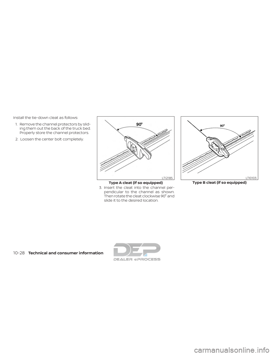
Install the tie-down cleat as follows:1. Remove the channel protectors by slid- ing them out the back of the truck bed.
Properly store the channel protectors.
2. Loosen the center bolt completely.
3. Insert the cleat into the channel per-pendicular to the channel as shown.
Then rotate the cleat clockwise 90° and
slide it to the desired location.
Type A cleat (if so equipped)
LTI2185
Type B cleat (if so equipped)
LTI0103
10-28Technical and consumer information
Page 552 of 682
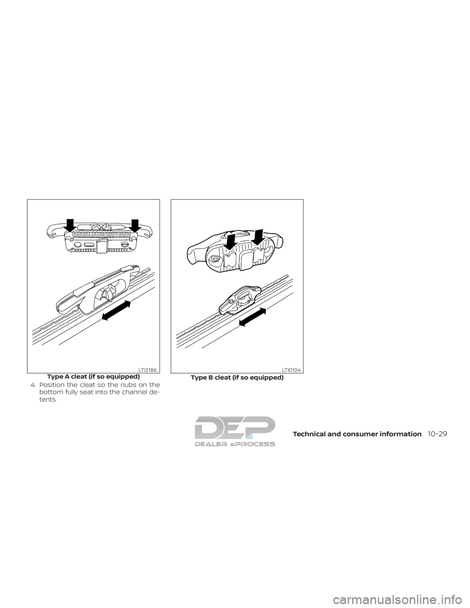
4. Position the cleat so the nubs on thebottom fully seat into the channel de-
tents.
Type A cleat (if so equipped)LTI2186
Type B cleat (if so equipped)
LTI0104
Technical and consumer information10-29
Page 553 of 682
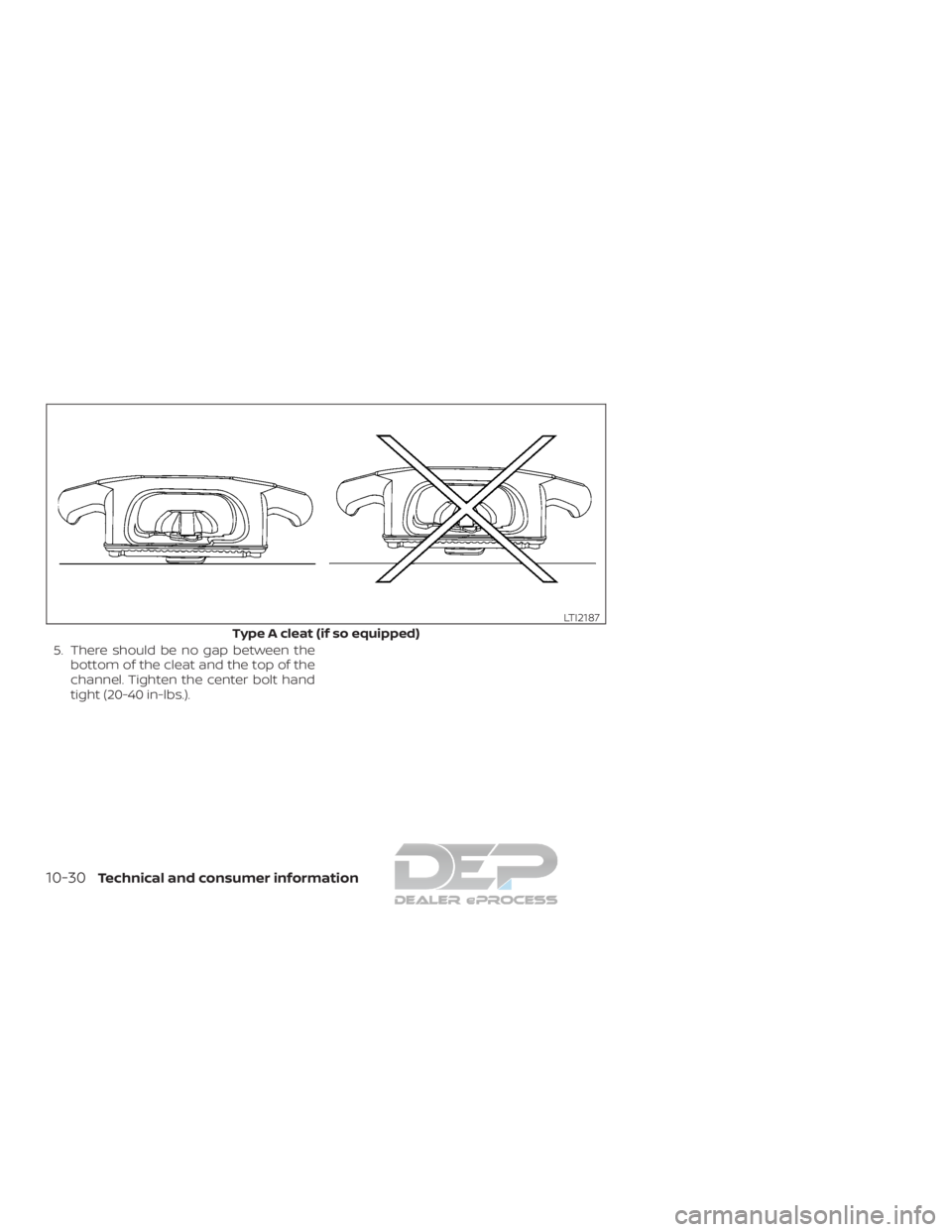
5. There should be no gap between thebottom of the cleat and the top of the
channel. Tighten the center bolt hand
tight (20-40 in-lbs.).
Type A cleat (if so equipped)
LTI2187
10-30Technical and consumer information
Page 554 of 682
Type B cleat (if so equipped)
WTI0124
Technical and consumer information10-31
Page 555 of 682
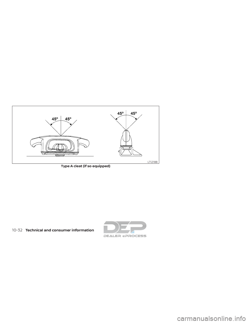
Type A cleat (if so equipped)
LTI2188
10-32Technical and consumer information
Page 556 of 682
CAUTION
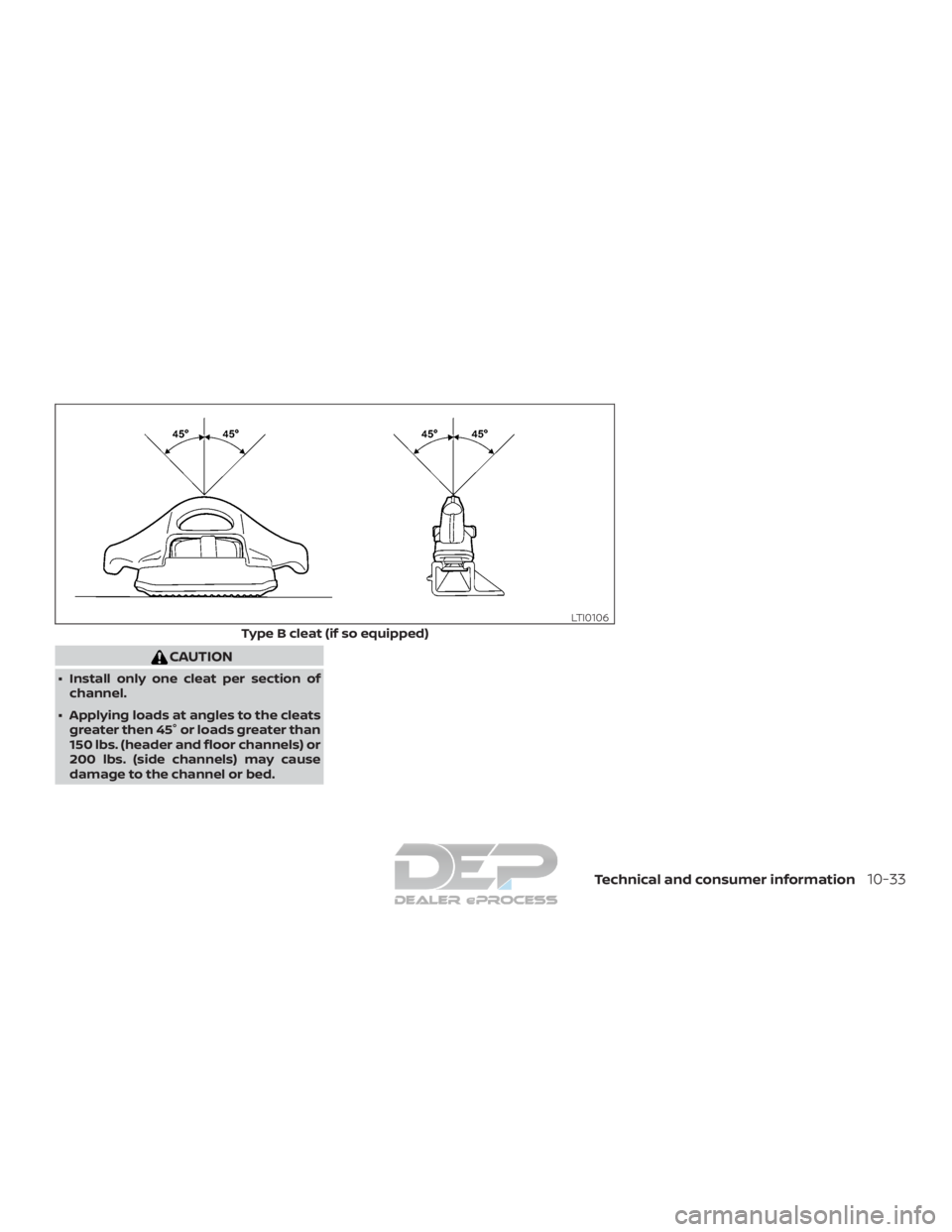
∙ Install only one cleat per section ofchannel.
∙ Applying loads at angles to the cleats greater then 45° or loads greater than
150 lbs. (header and floor channels) or
200 lbs. (side channels) may cause
damage to the channel or bed.
Type B cleat (if so equipped)
LTI0106
Technical and consumer information10-33
Page 557 of 682
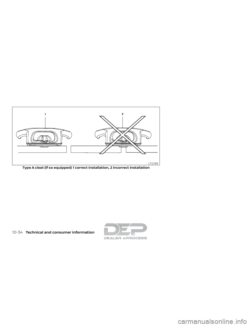
Type A cleat (if so equipped) 1 correct installation, 2 incorrect installation
LTI2189
10-34Technical and consumer information
Page 558 of 682
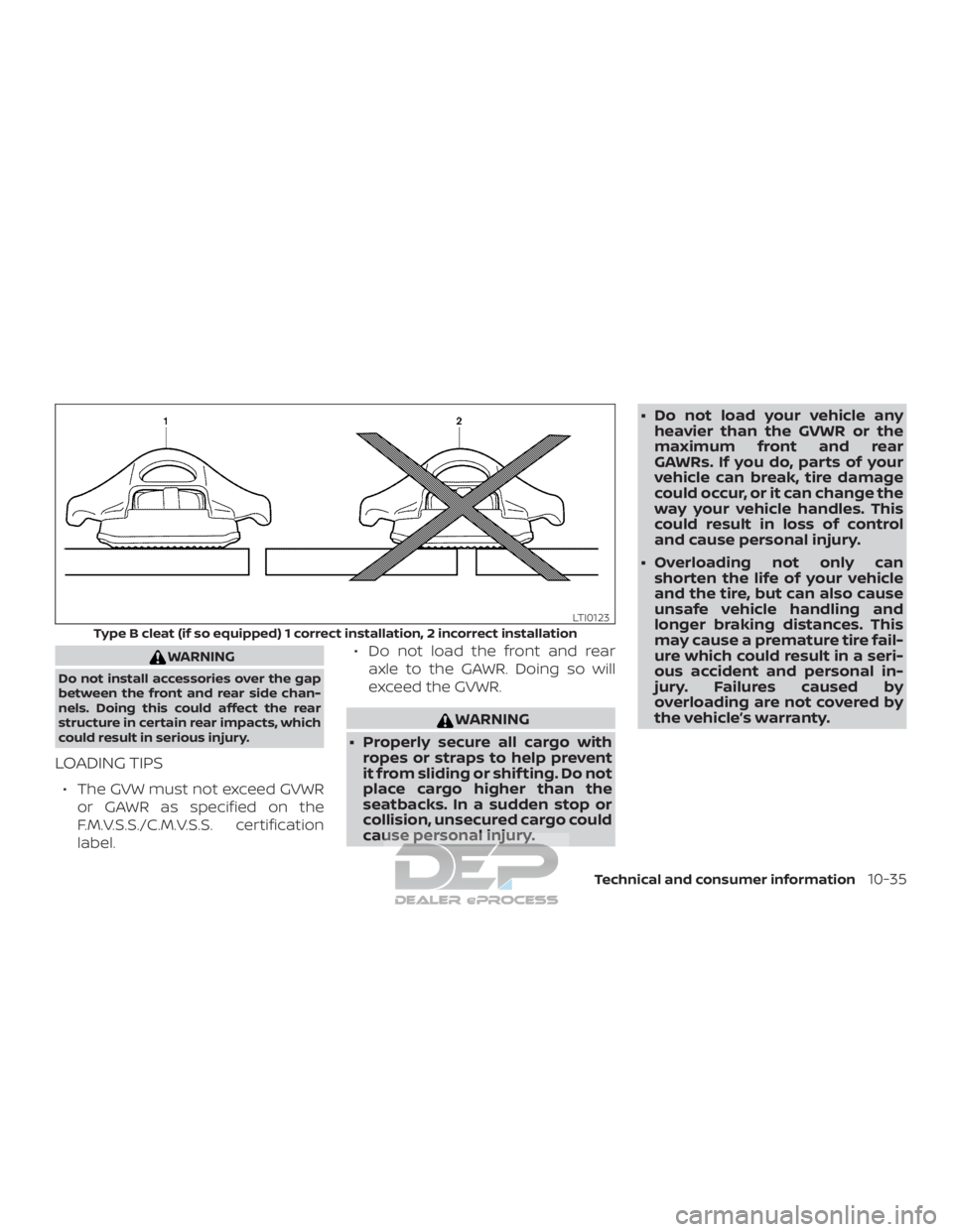
WARNING
Do not install accessories over the gap
between the front and rear side chan-
nels. Doing this could affect the rear
structure in certain rear impacts, which
could result in serious injury.
LOADING TIPS
∙ The GVW must not exceed GVWRor GAWR as specified on the
F.M.V.S.S./C.M.V.S.S. certification
label. ∙ Do not load the front and rear
axle to the GAWR. Doing so will
exceed the GVWR.
WARNING
∙ Properly secure all cargo with ropes or straps to help prevent
it from sliding or shif ting. Do not
place cargo higher than the
seatbacks. In a sudden stop or
collision, unsecured cargo could
cause personal injury. ∙ Do not load your vehicle any
heavier than the GVWR or the
maximum front and rear
GAWRs. If you do, parts of your
vehicle can break, tire damage
could occur, or it can change the
way your vehicle handles. This
could result in loss of control
and cause personal injury.
∙ Overloading not only can shorten the life of your vehicle
and the tire, but can also cause
unsafe vehicle handling and
longer braking distances. This
may cause a premature tire fail-
ure which could result in a seri-
ous accident and personal in-
jury. Failures caused by
overloading are not covered by
the vehicle’s warranty.
Type B cleat (if so equipped) 1 correct installation, 2 incorrect installation
LTI0123
Technical and consumer information10-35
Page 559 of 682
CREW CAB MODELS
Crew Cab short wheel base models
should not be used to carry a slide-in
camper.
KING CAB® MODELS
This information is provided for you to
properly install a slide-in camper and is
based on the National Highway Traffic
Safety Administration regulations. It is rec-
ommended that, before installing the
camper, you carefully read the following in-
formation and ensure that the camper
meets the specifications.
This information may not apply to some
Canada model vehicles.
SPECIAL BODY VEHICLES
Some vehicles are equipped with commer-
cial or camper bodies. However, this Own-
er’s Manual does not cover these options.
For additional information, refer to the
body manufacturer’s instruction manual.
LOCATION FOR CENTER OF
GRAVITY
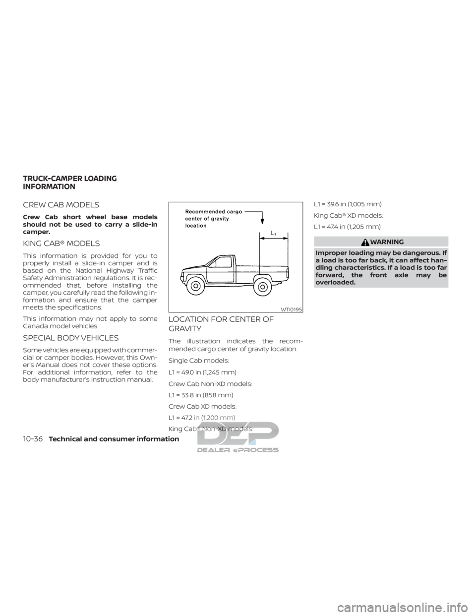
The illustration indicates the recom-
mended cargo center of gravity location.
Single Cab models:
L1 = 49.0 in (1,245 mm)
Crew Cab Non-XD models:
L1 = 33.8 in (858 mm)
Crew Cab XD models:
L1 = 47.2 in (1,200 mm)
King Cab® Non-XD models:L1 = 39.6 in (1,005 mm)
King Cab® XD models:
L1 = 47.4 in (1,205 mm)
WARNING
Improper loading may be dangerous. If
a load is too far back, it can affect han-
dling characteristics. If a load is too far
forward, the front axle may be
overloaded.
WTI0195
TRUCK-CAMPER LOADING
INFORMATION
10-36Technical and consumer information
Page 560 of 682
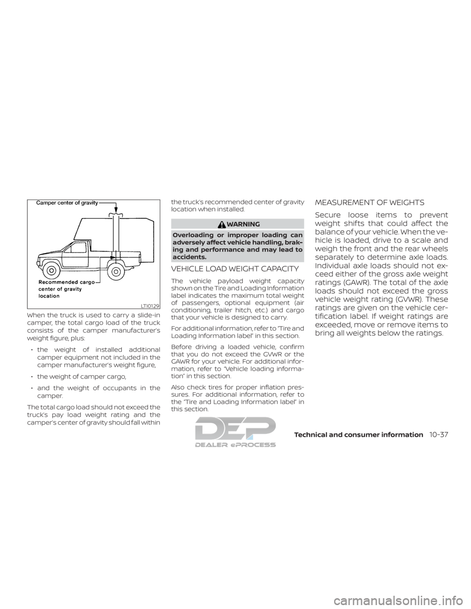
When the truck is used to carry a slide-in
camper, the total cargo load of the truck
consists of the camper manufacturer’s
weight figure, plus:∙ the weight of installed additional camper equipment not included in the
camper manufacturer’s weight figure,
∙ the weight of camper cargo,
∙ and the weight of occupants in the camper.
The total cargo load should not exceed the
truck’s pay load weight rating and the
camper’s center of gravity should fall within the truck’s recommended center of gravity
location when installed.
WARNING
Overloading or improper loading can
adversely affect vehicle handling, brak-
ing and performance and may lead to
accidents.
VEHICLE LOAD WEIGHT CAPACITY
The vehicle payload weight capacity
shown on the Tire and Loading Information
label indicates the maximum total weight
of passengers, optional equipment (air
conditioning, trailer hitch, etc.) and cargo
that your vehicle is designed to carry.
For additional information, refer to “Tire and
Loading Information label” in this section.
Before driving a loaded vehicle, confirm
that you do not exceed the GVWR or the
GAWR for your vehicle. For additional infor-
mation, refer to “Vehicle loading informa-
tion” in this section.
Also check tires for proper inflation pres-
sures. For additional information, refer to
the “Tire and Loading Information label” in
this section.
MEASUREMENT OF WEIGHTS
Secure loose items to prevent
weight shif ts that could affect the
balance of your vehicle. When the ve-
hicle is loaded, drive to a scale and
weigh the front and the rear wheels
separately to determine axle loads.
Individual axle loads should not ex-
ceed either of the gross axle weight
ratings (GAWR). The total of the axle
loads should not exceed the gross
vehicle weight rating (GVWR). These
ratings are given on the vehicle cer-
tification label. If weight ratings are
exceeded, move or remove items to
bring all weights below the ratings.
LTI0129
Technical and consumer information10-37
Trending: oil capacity, ignition, lumbar support, brake pads, change time, boot, differential
