trailer NISSAN TITAN 2019 Owner´s Manual
[x] Cancel search | Manufacturer: NISSAN, Model Year: 2019, Model line: TITAN, Model: NISSAN TITAN 2019Pages: 682, PDF Size: 7.99 MB
Page 34 of 682
15. Heated steering wheel switch(if so equipped) (P. 2-59)
Warning systems switch
(if so equipped) (P. 2-59)
16. Auxiliary jack* USB port*
17. Hazard warning flasher switch
(P. 6-2)
18. Trailer Brake Controller Unit (TBCU)
(if so equipped) (P. 2-66)
19. Climate control seat switch
(if so equipped) (P. 2-55)
Heated front seat switches
(if so equipped) (P. 2-56)
20. Vehicle Dynamic Control (VDC) OFF
switch (P. 2-60)
Front and rear sonar system OFF
switch (if so equipped) (P. 2-64)
21. 4WD shif t switch (if so equipped)
(P. 5-45)
22. Push-button ignition switch
(P. 5-11)
23. Tilt and telescopic steering wheel
control (P. 3-30) 24. Headlight aiming control
(if so equipped) (P. 2-49)
Power inverter switch
(if so equipped) (P. 2-63)
Cargo lamp switch (P. 2-55)
Electronic locking rear differential
(E-Lock) system switch
(if so equipped) (P. 2-62)
Hill descent control system switch
(if so equipped) (P. 2-61)
25. Headlight switch (P. 2-49) Fog light switch (if so equipped)
(P. 2-54)
Instrument brightness control
switches (P. 2-49)
Trip reset switch (P. 2-6)
*Refer to the separate NissanConnect®
Owner’s Manual
Refer to the page number indicated in
parenthesis for operating details.
Illustrated table of contents0-9
Page 125 of 682
Heated seat switches (if so equipped)..........2-56
Heated rear seat switches (if so equipped) ......2-57
Heated steering wheel switch (if so equipped) . . 2-59
Warning systems switch (if so equipped) .......2-59
Vehicle Dynamic Control (VDC) OFF switch ......2-60
Hill descent control switch (if so equipped) ......2-61
Electronic locking rear differential (E-Lock)
system switch (if so equipped) ..................2-62
Power inverter switch (if so equipped) ..........2-63
Front and rear sonar system OFF switch
(if so equipped) ................................. 2-64
Tow mode switch .............................. 2-65
E-call (SOS) button (if so equipped) .............2-65
Trailer Brake Controller Unit (TBCU)
(if so equipped) ................................. 2-66
Rear Door Alert (if so equipped) .................2-66
Power outlets .................................. 2-67
12v Outlets .................................. 2-67
120v outlets (if so equipped) .................2-69
Extended storage switch .......................2-70
Storage ........................................ 2-71
Front-door pockets .......................... 2-71
Rear-door pockets (if so equipped) ..........2-72
Console side pockets (if so equipped) ........2-72 Seatback pockets (if so equipped)
...........2-72
Under-seat storage (if so equipped) .........2-73
Console box storage trays
(if so equipped) ..............................2-74
Glovebox.................................... 2-75
Console box (if so equipped) .................2-75
Center armrest storage (if so equipped) .....2-76
Under front seat storage bin
(if so equipped) .............................. 2-77
Overhead sunglasses storage
(if so equipped) .............................. 2-77
Cup holders ................................. 2-78
Grocery hooks (if so equipped) ...............2-81
Bed liner storage bins (if so equipped) .......2-81
Cargo hooks (if so equipped) ................2-82
C-Channel cargo hooks (if so equipped) .....2-82
Window s....................................... 2-83
P o
wer windows ............................. 2-83
Rear power window switch
(if so equipped) .............................. 2-85
Rear sliding window (if so equipped) .........2-86
Interior lights ................................... 2-87
Console light (if so equipped) ................2-88
Map lights (if so equipped) ...................2-88
Page 128 of 682
15. Heated steering wheel switch(if so equipped) (P. 2-59)
Warning systems switch
(if so equipped) (P. 2-59)
16. Auxiliary jack* USB port*
17. Hazard warning flasher switch
(P. 6-2)
18. Trailer Brake Controller Unit (TBCU)
(if so equipped) (P. 2-66)
19. Climate control seat switch
(if so equipped) (P. 2-55)
Heated front seat switches
(if so equipped) (P. 2-56)
20. Vehicle Dynamic Control (VDC) OFF
switch (P. 2-60)
Front and rear sonar system OFF
switch (if so equipped) (P. 2-64)
21. 4WD shif t switch (if so equipped)
(P. 5-45)
22. Push-button ignition switch
(P. 5-11)
23. Tilt and telescopic steering wheel
control (P. 3-30) 24. Headlight aiming control
(if so equipped) (P. 2-49)
Power inverter switch
(if so equipped) (P. 2-63)
Cargo lamp switch (P. 2-55)
Electronic locking rear differential
(E-Lock) system switch
(if so equipped) (P. 2-62)
Hill descent control system switch
(if so equipped) (P. 2-61)
25. Headlight switch (P. 2-49) Fog light switch (if so equipped)
(P. 2-54)
Instrument brightness control
switches (P. 2-49)
Trip reset switch (P. 2-6)
*Refer to the separate NissanConnect®
Owner’s Manual
Refer to the page number indicated in
parenthesis for operating details.
Instruments and controls2-5
Page 154 of 682
Menu itemResult
Rain Sensor (if so equipped) Allows user to turn the rain sensor feature on or off. For additional information, refer to “Wiper and washer
switch” in this section.
Speed Dependent (if so equipped) Allows user to turn the speed dependent feature on or off. For additional information, refer to “Wiper and washer switch” in this section.
Memory Seat (ADP) (if so equipped) Displays available memory seat options.
Exit Seat Slide Allows the user to turn the exit seat slide on or off. When turned on, this feature will move the driver’s seat
backward for an easy exit when the ignition is turned off and the driver’s door is opened. Af ter getting into
the vehicle and placing the ignition switch in the ACC position, the driver’s seat will move to the previous set
position. For additional information, refer to “Automatic drive positioner” in the “Pre-driving checks and ad-
justments” section of this manual.
Exit Steering Up Allows the user to turn the exit steering up feature on or off. When turned on, this feature will move the steer-
ing wheel upward for an easy exit when the ignition is turned off and the driver’s door is opened. Af ter get-
ting into the vehicle and placing the ignition switch in the ACC position, the steering wheel moves to the pre-
vious position. For additional information, refer to “Automatic drive positioner” in the “Pre-driving checks and
adjustments” section of this manual.
Reverse Tilt Mirror (if so equipped) Displays reverse tilt mirror information.
Towing Settings (if so equipped) Displays available towing settings options.
Trailer light check Allows user to select a mode in which the vehicle will test various lights that could affect a trailer if con-
nected properly. This feature can also be activated using the NISSAN Intelligent Key®. For additional
information, refer to “NISSAN Intelligent Key®” in the “Pre-driving checks and adjustments” and “Towing a
trailer” in the Technical and consumer information” sections of this manual.
Instruments and controls2-31
Page 175 of 682
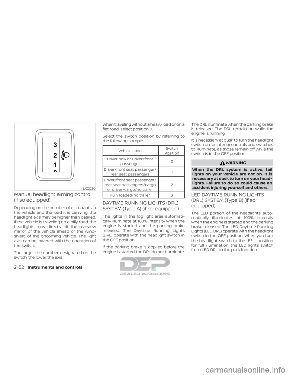
Manual headlight aiming control
(if so equipped)
Depending on the number of occupants in
the vehicle and the load it is carrying, the
headlight axis may be higher than desired.
If the vehicle is traveling on a hilly road, the
headlights may directly hit the rearview
mirror of the vehicle ahead or the wind-
shield of the oncoming vehicle. The light
axis can be lowered with the operation of
the switch.
The larger the number designated on the
switch, the lower the axis.When traveling without a heavy load or on a
flat road, select position 0.
Select the switch position by referring to
the following sample.
Vehicle Load
Switch
Position
Driver only or Driver/front passenger 0
Driver/front seat passenger/ rear seat passengers 1
Driver/front seat passenger/ rear seat passengers/cargo or driver/cargo/no trailer 2
Fully loaded/no trailer 3
DAYTIME RUNNING LIGHTS (DRL)
SYSTEM (Type A) (if so equipped)
The lights in the fog light area automati-
cally illuminate at 100% intensity when the
engine is started and the parking brake
released. The Daytime Running Lights
(DRL) operate with the headlight switch in
the OFF position.
If the parking brake is applied before the
engine is started, the DRL do not illuminate. The DRL illuminate when the parking brake
is released. The DRL remain on while the
engine is running.
It is necessary at dusk to turn the headlight
switch on for interior controls and switches
to illuminate, as those remain off while the
switch is in the OFF position.
WARNING
When the DRL system is active, tail
lights on your vehicle are not on. It is
necessary at dusk to turn on your head-
lights. Failure to do so could cause an
accident injuring yourself and others.
LED DAYTIME RUNNING LIGHTS
(DRL) SYSTEM (Type B) (if so
equipped)
The LED portion of the headlights auto-
matically illuminates at 100% intensity
when the engine is started and the parking
brake released. The LED Daytime Running
Lights (LED DRL) operate with the headlight
switch in the OFF position. When you turn
the headlight switch to the
position
for full illumination, the LED lights switch
from LED DRL to the park function.
LIC2230
2-52Instruments and controls
Page 188 of 682
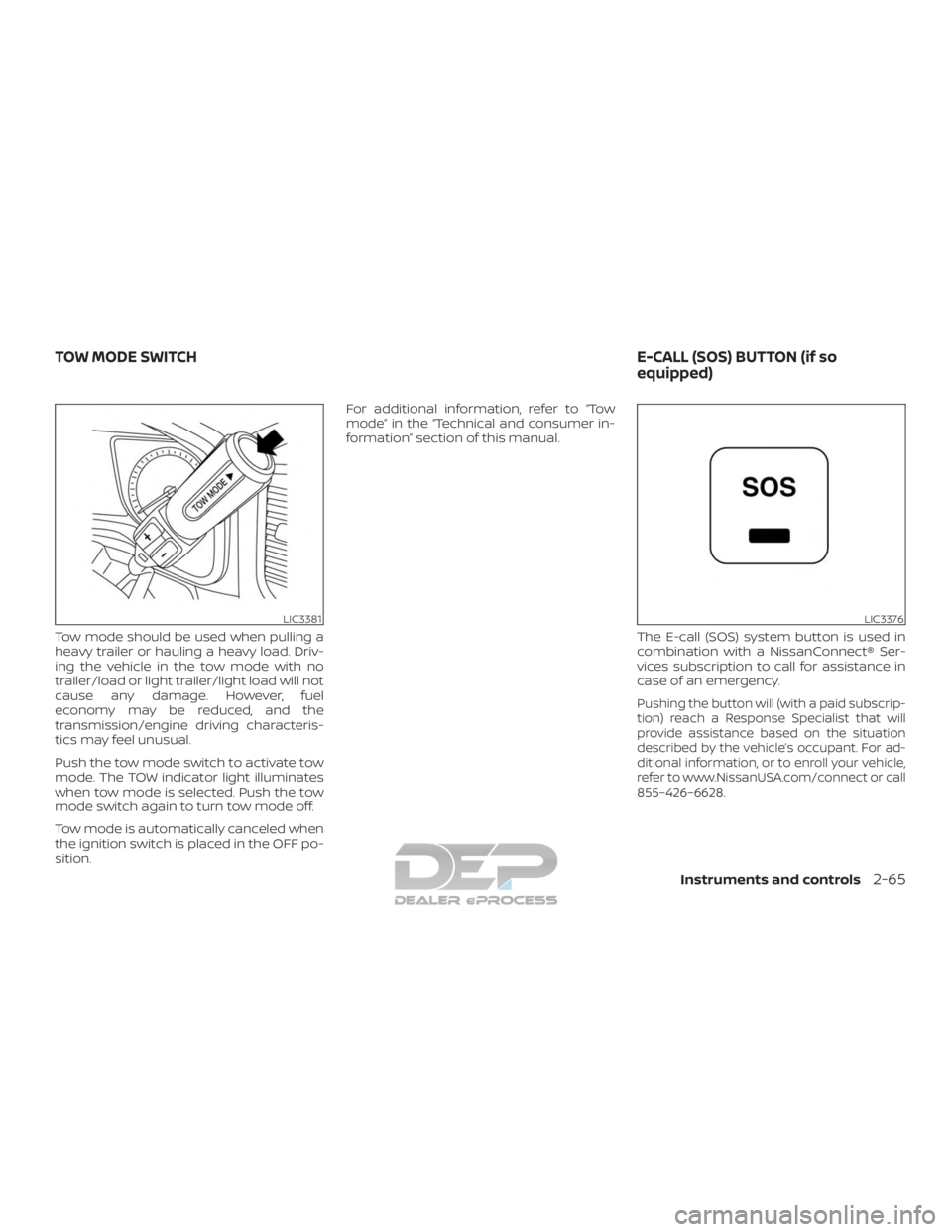
Tow mode should be used when pulling a
heavy trailer or hauling a heavy load. Driv-
ing the vehicle in the tow mode with no
trailer/load or light trailer/light load will not
cause any damage. However, fuel
economy may be reduced, and the
transmission/engine driving characteris-
tics may feel unusual.
Push the tow mode switch to activate tow
mode. The TOW indicator light illuminates
when tow mode is selected. Push the tow
mode switch again to turn tow mode off.
Tow mode is automatically canceled when
the ignition switch is placed in the OFF po-
sition.For additional information, refer to “Tow
mode” in the “Technical and consumer in-
formation” section of this manual.
The E-call (SOS) system button is used in
combination with a NissanConnect® Ser-
vices subscription to call for assistance in
case of an emergency.
Pushing the button will (with a paid subscrip-
tion) reach a Response Specialist that will
provide assistance based on the situation
described by the vehicle’s occupant. For ad-
ditional information, or to enroll your vehicle,
refer to www.NissanUSA.com/connect or call
855–426–6628.
LIC3381LIC3376
TOW MODE SWITCH E-CALL (SOS) BUTTON (if so
equipped)
Instruments and controls2-65
Page 189 of 682
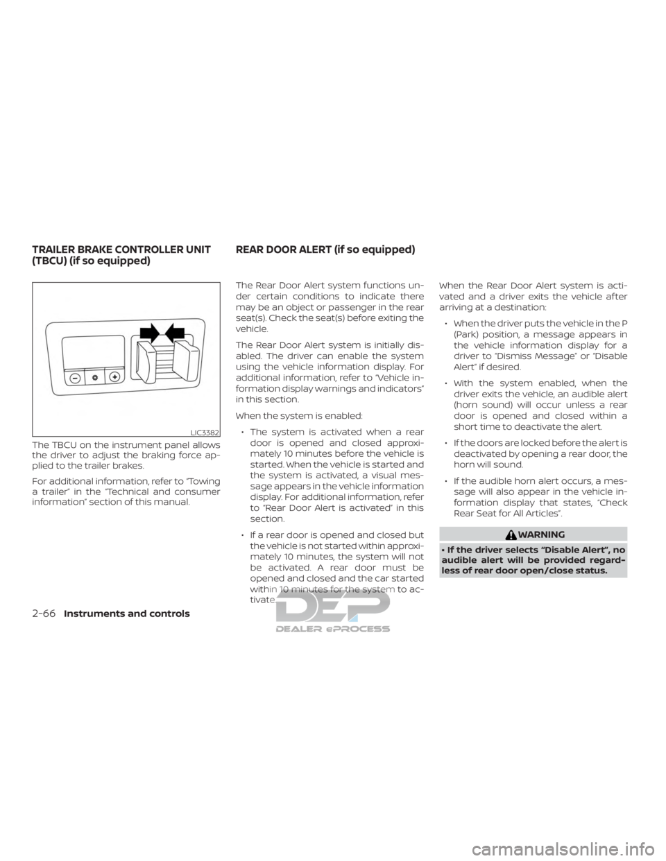
The TBCU on the instrument panel allows
the driver to adjust the braking force ap-
plied to the trailer brakes.
For additional information, refer to “Towing
a trailer” in the “Technical and consumer
information” section of this manual.The Rear Door Alert system functions un-
der certain conditions to indicate there
may be an object or passenger in the rear
seat(s). Check the seat(s) before exiting the
vehicle.
The Rear Door Alert system is initially dis-
abled. The driver can enable the system
using the vehicle information display. For
additional information, refer to “Vehicle in-
formation display warnings and indicators”
in this section.
When the system is enabled:
∙ The system is activated when a rear door is opened and closed approxi-
mately 10 minutes before the vehicle is
started. When the vehicle is started and
the system is activated, a visual mes-
sage appears in the vehicle information
display. For additional information, refer
to “Rear Door Alert is activated” in this
section.
∙ If a rear door is opened and closed but the vehicle is not started within approxi-
mately 10 minutes, the system will not
be activated. A rear door must be
opened and closed and the car started
within 10 minutes for the system to ac-
tivate. When the Rear Door Alert system is acti-
vated and a driver exits the vehicle af ter
arriving at a destination:
∙ When the driver puts the vehicle in the P (Park) position, a message appears in
the vehicle information display for a
driver to “Dismiss Message” or “Disable
Alert” if desired.
∙ With the system enabled, when the driver exits the vehicle, an audible alert
(horn sound) will occur unless a rear
door is opened and closed within a
short time to deactivate the alert.
∙ If the doors are locked before the alert is deactivated by opening a rear door, the
horn will sound.
∙ If the audible horn alert occurs, a mes- sage will also appear in the vehicle in-
formation display that states, “Check
Rear Seat for All Articles”.
WARNING
• If the driver selects “Disable Alert”, no
audible alert will be provided regard-
less of rear door open/close status.
LIC3382
TRAILER BRAKE CONTROLLER UNIT
(TBCU) (if so equipped) REAR DOOR ALERT (if so equipped)
2-66Instruments and controls
Page 236 of 682
∙ The request switch (if so equipped) onthe driver’s door is pushed and the In-
telligent Key is in range of the door
handle.
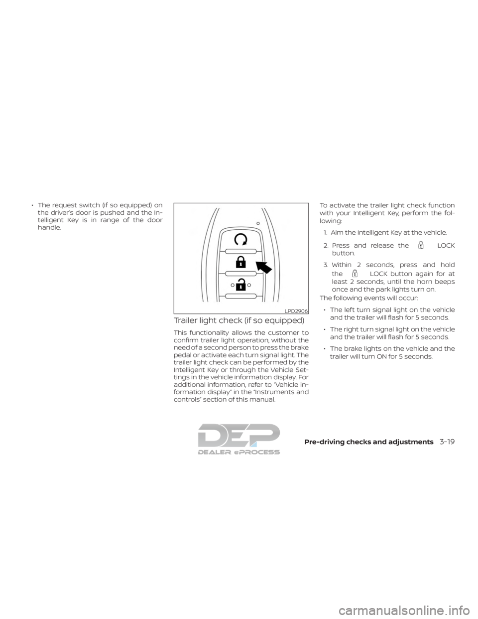
Trailer light check (if so equipped)
This functionality allows the customer to
confirm trailer light operation, without the
need of a second person to press the brake
pedal or activate each turn signal light. The
trailer light check can be performed by the
Intelligent Key or through the Vehicle Set-
tings in the vehicle information display. For
additional information, refer to “Vehicle in-
formation display” in the “Instruments and
controls” section of this manual. To activate the trailer light check function
with your Intelligent Key, perform the fol-
lowing:
1. Aim the Intelligent Key at the vehicle.
2. Press and release the
LOCK
button.
3. Within 2 seconds, press and hold the
LOCK button again for at
least 2 seconds, until the horn beeps
once and the park lights turn on.
The following events will occur:
∙ The lef t turn signal light on the vehicle and the trailer will flash for 5 seconds.
∙ The right turn signal light on the vehicle and the trailer will flash for 5 seconds.
∙ The brake lights on the vehicle and the trailer will turn ON for 5 seconds.
LPD2906
Pre-driving checks and adjustments3-19
Page 237 of 682
NOTE:
If the ignition switch is in the OFF posi-
tion, the park lights will turn off af ter the
events above occur. If ignition switch is
in the ON position, lights will stay on for
45 seconds af ter trailer light check. If the
trailer lights do not work properly, check
the connections and bulbs. If the vehicle
lights do not turn on, check the bulbs. If
the trailer light check routine fails to
start, ensure the following vehicle condi-
tions:∙ The vehicle is NOT moving, 0 mph (0 km/h)
∙ Brake switch is NOT depressed
∙ Lef t or right flasher is OFF
∙ Trailer light check configuration is NOT disabled and available in the meter
towing settings
∙ The hazard switch is NOT turned ON
∙ The shif t position is fully in P (Park) posi- tion
∙ Vehicle is within Remote Keyless Entry range
Answer back horn feature
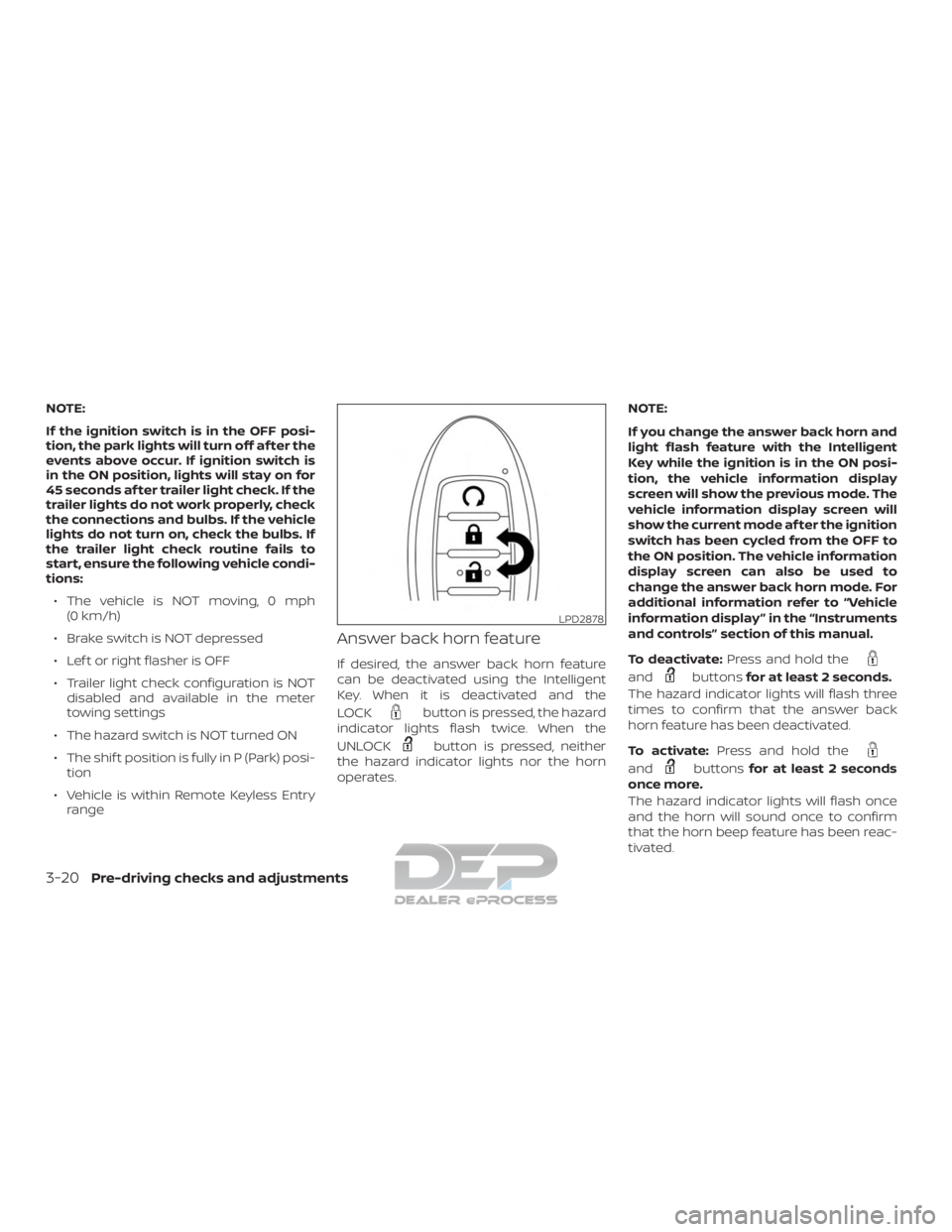
If desired, the answer back horn feature
can be deactivated using the Intelligent
Key. When it is deactivated and the
LOCK
button is pressed, the hazard
indicator lights flash twice. When the
UNLOCK
button is pressed, neither
the hazard indicator lights nor the horn
operates. NOTE:
If you change the answer back horn and
light flash feature with the Intelligent
Key while the ignition is in the ON posi-
tion, the vehicle information display
screen will show the previous mode. The
vehicle information display screen will
show the current mode af ter the ignition
switch has been cycled from the OFF to
the ON position. The vehicle information
display screen can also be used to
change the answer back horn mode. For
additional information refer to “Vehicle
information display ” in the “Instruments
and controls” section of this manual.
To deactivate:
Press and hold the
andbuttonsfor at least 2 seconds.
The hazard indicator lights will flash three
times to confirm that the answer back
horn feature has been deactivated.
To activate: Press and hold the
andbuttonsfor at least 2 seconds
once more.
The hazard indicator lights will flash once
and the horn will sound once to confirm
that the horn beep feature has been reac-
tivated.
LPD2878
3-20Pre-driving checks and adjustments
Page 246 of 682
∙ Do not attempt to top off the fuel tankaf ter the fuel pump nozzle shuts off
automatically. Continued refueling
may cause fuel overflow, resulting in
fuel spray and possibly a fire.
∙ Use only an original equipment type fuel-filler cap as a replacement. It has
a built-in safety valve needed for
proper operation of the fuel system
and emission control system. An in-
correct cap can result in a serious mal-
function and possible injury. It could
also cause the
Malfunction Indi-
cator Light (MIL) to come on.
∙ Never pour fuel into the throttle body to attempt to start your vehicle.
∙ Do not fill a portable fuel container in the vehicle or trailer. Static electricity
can cause an explosion of flammable
liquid, vapor or gas in any vehicle or
trailer. To reduce the risk of serious
injury or death when filling portable
fuel containers:
– Always place the container on the ground when filling.
– Do not use electronic devices when filling. – Keep the pump nozzle in contact
with the container while you are
filling it.
– Use only approved portable fuel containers for flammable liquid.
CAUTION
∙ Do not use E-15 or E-85 fuel in yourvehicle. For additional information,
refer to “Fuel recommendation” in the
“Technical and consumer informa-
tion” section of this manual.
∙ The Loose Fuel Cap warning message will appear if the fuel-filler cap is not
properly tightened. It may take a few
driving trips for the message to be
displayed. Failure to tighten the fuel-
filler cap properly af ter the Loose Fuel
Cap warning message appears may
cause the
Malfunction Indicator
Light (MIL) to illuminate. ∙ Failure to tighten the fuel-filler cap
properly may cause the
Mal-
function Indicator Light (MIL) to illumi-
nate. If the
light illuminates be-
cause the fuel-filler cap is loose or
missing, tighten or install the cap and
continue to drive the vehicle.
The
light should turn off af ter a
few driving trips. If the
light does
not turn off af ter a few driving trips,
have the vehicle inspected. It is rec-
ommended that you visit a NISSAN
dealer for this service.
∙ For additional information, refer to “Malfunction Indicator Light (MIL)” in
the “Instruments and controls” sec-
tion of this manual.
∙ If fuel is spilled on the vehicle body, flush it away with water to avoid paint
damage.
Pre-driving checks and adjustments3-29