battery NISSAN X-TRAIL 2001 Service Owner's Manual
[x] Cancel search | Manufacturer: NISSAN, Model Year: 2001, Model line: X-TRAIL, Model: NISSAN X-TRAIL 2001Pages: 3833, PDF Size: 39.49 MB
Page 369 of 3833
EC-19
C
D
E
F
G
H
I
J
K
L
M
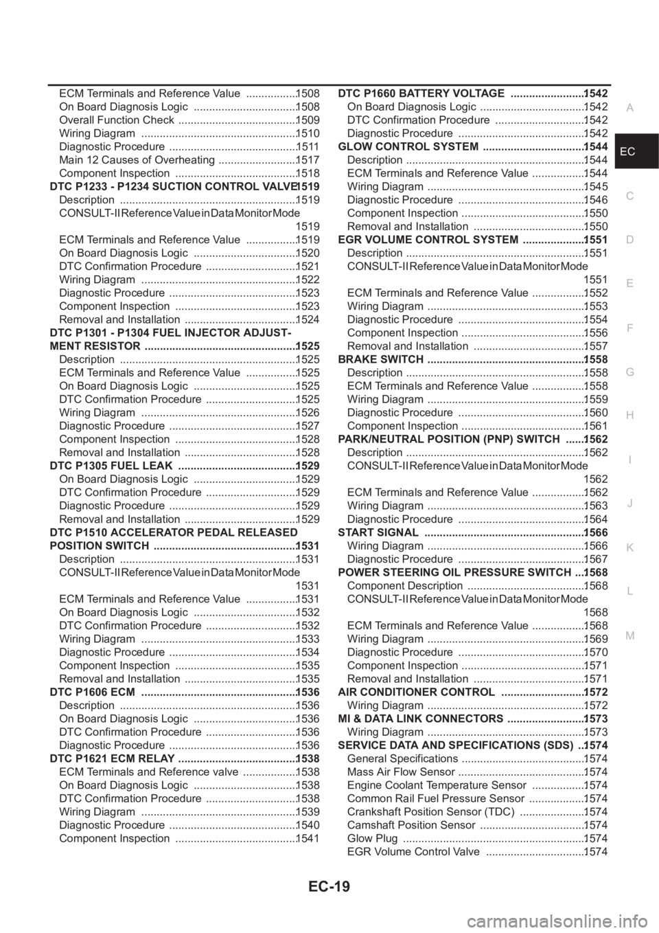
ECA ECM Terminals and Reference Value .................1508
On Board Diagnosis Logic ..................................1508
Overall Function Check .......................................1509
Wiring Diagram ...................................................1510
Diagnostic Procedure ..........................................1511
Main 12 Causes of Overheating ..........................1517
Component Inspection ........................................1518
DTC P1233 - P1234 SUCTION CONTROL VALVE 1519
Description ..........................................................1519
CONSULT-II Reference Value in Data Monitor Mode
1519
ECM Terminals and Reference Value .................1519
On Board Diagnosis Logic ..................................1520
DTC Confirmation Procedure ..............................1521
Wiring Diagram ...................................................1522
Diagnostic Procedure ..........................................1523
Component Inspection ........................................1523
Removal and Installation .....................................1524
DTC P1301 - P1304 FUEL INJECTOR ADJUST-
MENT RESISTOR .................................................. 1525
Description ..........................................................1525
ECM Terminals and Reference Value .................1525
On Board Diagnosis Logic ..................................1525
DTC Confirmation Procedure ..............................1525
Wiring Diagram ...................................................1526
Diagnostic Procedure ..........................................1527
Component Inspection ........................................1528
Removal and Installation .....................................1528
DTC P1305 FUEL LEAK .......................................1529
On Board Diagnosis Logic ..................................1529
DTC Confirmation Procedure ..............................1529
Diagnostic Procedure ..........................................1529
Removal and Installation .....................................1529
DTC P1510 ACCELERATOR PEDAL RELEASED
POSITION SWITCH ...............................................1531
Description ..........................................................1531
CONSULT-II Reference Value in Data Monitor Mode
1531
ECM Terminals and Reference Value .................1531
On Board Diagnosis Logic ..................................1532
DTC Confirmation Procedure ..............................1532
Wiring Diagram ...................................................1533
Diagnostic Procedure ..........................................1534
Component Inspection ........................................1535
Removal and Installation .....................................1535
DTC P1606 ECM ...................................................1536
Description ..........................................................1536
On Board Diagnosis Logic ..................................1536
DTC Confirmation Procedure ..............................
1536
Diagnostic Procedure ..........................................1536
DTC P1621 ECM RELAY .......................................1538
ECM Terminals and Reference valve ..................1538
On Board Diagnosis Logic ..................................1538
DTC Confirmation Procedure ..............................1538
Wiring Diagram ...................................................1539
Diagnostic Procedure ..........................................1540
Component Inspection ........................................1541DTC P1660 BATTERY VOLTAGE .........................1542
On Board Diagnosis Logic ...................................1542
DTC Confirmation Procedure ..............................1542
Diagnostic Procedure ..........................................1542
GLOW CONTROL SYSTEM ..................................1544
Description ...........................................................1544
ECM Terminals and Reference Value ..................1544
Wiring Diagram ....................................................1545
Diagnostic Procedure ..........................................1546
Component Inspection .........................................1550
Removal and Installation .....................................1550
EGR VOLUME CONTROL SYSTEM .....................1551
Description ...........................................................1551
CONSULT-II Reference Value in Data Monitor Mode
1551
ECM Terminals and Reference Value ..................1552
Wiring Diagram ....................................................1553
Diagnostic Procedure ..........................................1554
Component Inspection .........................................1556
Removal and Installation .....................................1557
BRAKE SWITCH ....................................................1558
Description ...........................................................1558
ECM Terminals and Reference Value ..................1558
Wiring Diagram ....................................................1559
Diagnostic Procedure ..........................................1560
Component Inspection .........................................1561
PARK/NEUTRAL POSITION (PNP) SWITCH .......1562
Description ...........................................................1562
CONSULT-II Reference Value in Data Monitor Mode
1562
ECM Terminals and Reference Value ..................1562
Wiring Diagram ....................................................1563
Diagnostic Procedure ..........................................1564
START SIGNAL .....................................................1566
Wiring Diagram ....................................................1566
Diagnostic Procedure ..........................................1567
POWER STEERING OIL PRESSURE SWITCH ....1568
Component Description .......................................1568
CONSULT-II Reference Value in Data Monitor Mode
1568
ECM Terminals and Reference Value ..................1568
Wiring Diagram ....................................................1569
Diagnostic Procedure ..........................................1570
Component Inspection .........................................1571
Removal and Installation .....................................1571
AIR CONDITIONER CONTROL ............................1572
Wiring Diagram ....................................................1572
MI & DATA LINK CONNECTORS ..........................1573
Wiring Diagram ....................................................1573
SERVICE DATA AND SPECIFICATIONS (SDS) ...1574
General Specifications ......................................... 1574
Mass Air Flow Sensor ..........................................1574
Engine Coolant Temperature Sensor ..................1574
Common Rail Fuel Pressure Sensor ...................1574
Crankshaft Position Sensor (TDC) ......................1574
Camshaft Position Sensor ...................................1574
Glow Plug ............................................................1574
EGR Volume Control Valve .................................1574
Page 375 of 3833

PRECAUTIONS
EC-25
[QR25(WITH EURO-OBD)]
C
D
E
F
G
H
I
J
K
L
MA
EC
PRECAUTIONSPFP:00001
Precautions for Supplemental Restraint System (SRS) “AIR BAG” and “SEAT
BELT PRE-TENSIONER”
EBS00NBQ
The Supplemental Restraint System such as “AIR BAG” and “SEAT BELT PRE-TENSIONER”, used along
with a front seat belt, helps to reduce the risk or severity of injury to the driver and front passenger for certain
types of collision. Information necessary to service the system safely is included in the SRS and SB section of
this Service Manual.
WARNING:
●To avoid rendering the SRS inoperative, which could increase the risk of personal injury or death
in the event of a collision which would result in air bag inflation, all maintenance must be per-
formed by an authorized NISSAN/INFINITI dealer.
●Improper maintenance, including incorrect removal and installation of the SRS, can lead to per-
sonal injury caused by unintentional activation of the system. For removal of Spiral Cable and Air
Bag Module, see the SRS section.
●Do not use electrical test equipment on any circuit related to the SRS unless instructed to in this
Service Manual. SRS wiring harnesses can be identified by yellow and/or orange harness connec-
tors.
On Board Diagnostic (OBD) System of Engine and A/TEBS00M04
The ECM has an on board diagnostic system. It will light up the malfunction indicator (MI) to warn the driver of
a malfunction causing emission deterioration.
CAUTION:
●Be sure to turn the ignition switch OFF and disconnect the negative battery terminal before any
repair or inspection work. The open/short circuit of related switches, sensors, solenoid valves,
etc. will cause the MI to light up.
●Be sure to connect and lock the connectors securely after work. A loose (unlocked) connector will
cause the MI to light up due to the open circuit. (Be sure the connector is free from water, grease,
dirt, bent terminals, etc.)
●Certain systems and components, especially those related to OBD, may use a new style slide-
locking type harness connector. For description and how to disconnect, refer to PG-68, "
HAR-
NESS CONNECTOR" .
●Be sure to route and secure the harnesses properly after work. The interference of the harness
with a bracket, etc. may cause the MI to light up due to the short circuit.
●Be sure to connect rubber tubes properly after work. A misconnected or disconnected rubber tube
may cause the MI to light up due to the malfunction of the fuel injection system, etc.
●Be sure to erase the unnecessary malfunction information (repairs completed) from the ECM and
TCM (Transmission control module) before returning the vehicle to the customer.
PrecautionEBS00M05
●Always use a 12 volt battery as power source.
●Do not attempt to disconnect battery cables while engine is
running.
●Before connecting or disconnecting the ECM harness con-
nector, turn ignition switch OFF and disconnect negative
battery terminal. Failure to do so may damage the ECM
because battery voltage is applied to ECM even if ignition
switch is turned off.
●Before removing parts, turn ignition switch OFF and then
disconnect battery ground cable.
SEF289H
Page 376 of 3833

EC-26
[QR25(WITH EURO-OBD)]
PRECAUTIONS
●Do not disassemble ECM.
●If a battery terminal is disconnected, the memory will return
to the ECM value.
The ECM will now start to self-control at its initial value.
Engine operation can vary slightly when the terminal is dis-
connected. However, this is not an indication of a malfunc-
tion. Do not replace parts because of a slight variation.
●When connecting ECM harness connector, fasten it
securely with a lever as far as it will go as shown at right.
●When connecting or disconnecting pin connectors into or
from ECM, take care not to damage pin terminals (bend or
break).
Make sure that there are not any bends or breaks on ECM
pin terminal, when connecting pin connectors.
●Securely connect ECM harness connectors.
A poor connection can cause an extremely high (surge)
voltage to develop in coil and condenser, thus resulting in
damage to ICs.
●Keep engine control system harness at least 10 cm (4 in)
away from adjacent harness, to prevent engine control sys-
tem malfunctions due to receiving external noise, degraded
operation of ICs, etc.
●Keep engine control system parts and harness dry.
●Before replacing ECM, perform “ECM Terminals and Refer-
ence Value” inspection and make sure ECM functions prop-
erly. Refer to EC-819
.
●Handle mass air flow sensor carefully to avoid damage.
●Do not disassemble mass air flow sensor.
●Do not clean mass air flow sensor with any type of deter-
gent.
●Do not disassemble electric throttle control actuator.
●Even a slight leak in the air intake system can cause seri-
ous incidents.
●Do not shock or jar the camshaft position sensor (PHASE),
crankshaft position sensor (POS).
SEF707Y
SEF908W
PBIB0090E
MEF040D
Page 383 of 3833

ENGINE CONTROL SYSTEM
EC-33
[QR25(WITH EURO-OBD)]
C
D
E
F
G
H
I
J
K
L
MA
EC
System ChartEBS00M0B
*1: This sensor is not used to control the engine system under normal conditions.
*2: These signals are sent to the ECM through CAN communication line.
Multiport Fuel Injection (MFI) SystemEBS00M0C
INPUT/OUTPUT SIGNAL CHART
*1: Under normal conditions, this sensor is not for engine control operation.
SYSTEM DESCRIPTION
The amount of fuel injected from the fuel injector is determined by the ECM. The ECM controls the length of
time the valve remains open (injection pulse duration). The amount of fuel injected is a program value in the
ECM memory. The program value is preset by engine operating conditions. These conditions are determined
Input (Sensor) ECM Function Output (Actuator)
●Camshaft position sensor (PHASE)
●Crankshaft position sensor (POS)
●Mass air flow sensor
●Engine coolant temperature sensor
●Heated oxygen sensor 1
●Throttle position sensor
●Accelerator pedal position sensor
●Park/neutral position (PNP) switch
●Intake air temperature sensor
●Power steering pressure sensor
●Ignition switch
●Battery voltage
●Knock sensor
●Refrigerant pressure sensor
●Heated oxygen sensor 2 *1
●TCM (Transmission control module) *2
●Wheel sensor
●Air conditioner switch
●Electrical loadFuel injection & mixture ratio control Fuel injectors
Electronic ignition system Power transistors
Fuel pump control Fuel pump relay
On board diagnostic system MI (On the instrument panel)
Heated oxygen sensor 1 heater control Heated oxygen sensor 1 heater
Heated oxygen sensor 2 heater control Heated oxygen sensor 2 heater
Power valve control VIAS control solenoid valve
EVAP canister purge flow controlEVAP canister purge volume control
solenoid valve
Air conditioning cut control Air conditioner relay
Cooling fan control Cooling fan relays
Sensor Input Signal to ECMECM func-
tionActuator
Crankshaft position sensor (POS)
Engine speed
Piston position
Fuel injec-
tion & mix-
ture ratio
controlFuel injectors Camshaft position sensor (PHASE)
Mass air flow sensor Amount of intake air
Engine coolant temperature sensor Engine coolant temperature
Heated oxygen sensor 1 Density of oxygen in exhaust gas
Throttle position sensor Throttle position
Accelerator pedal position sensor Accelerator pedal position
Park/neutral position (PNP) switch Gear position
Ignition switch Start signal
Knock sensor Engine knocking condition
Battery Battery voltage
Power steering pressure sensor Power steering operation
Heated oxygen sensor 2 *
1Density of oxygen in exhaust gas
Wheel sensor Vehicle speed
Air conditioner switch Air conditioner operation
Page 385 of 3833

ENGINE CONTROL SYSTEM
EC-35
[QR25(WITH EURO-OBD)]
C
D
E
F
G
H
I
J
K
L
MA
EC
inally designed. Both manufacturing differences (i.e., mass air flow sensor hot film) and characteristic changes
during operation (i.e., injector clogging) directly affect mixture ratio.
Accordingly, the difference between the basic and theoretical mixture ratios is monitored in this system. This is
then computed in terms of “injection pulse duration” to automatically compensate for the difference between
the two ratios.
“Fuel trim” refers to the feedback compensation value compared against the basic injection duration. Fuel trim
includes short term fuel trim and long term fuel trim.
“Short term fuel trim” is the short-term fuel compensation used to maintain the mixture ratio at its theoretical
value. The signal from heated oxygen sensor 1 indicates whether the mixture ratio is RICH or LEAN compared
to the theoretical value. The signal then triggers a reduction in fuel volume if the mixture ratio is rich, and an
increase in fuel volume if it is lean.
“Long term fuel trim” is overall fuel compensation carried out long-term to compensate for continual deviation
of the short term fuel trim from the central value. Such deviation will occur due to individual engine differences,
wear over time and changes in the usage environment.
FUEL INJECTION TIMING
Two types of systems are used.
Sequential Multiport Fuel Injection System
Fuel is injected into each cylinder during each engine cycle according to the firing order. This system is used
when the engine is running.
Simultaneous Multiport Fuel Injection System
Fuel is injected simultaneously into all four cylinders twice each engine cycle. In other words, pulse signals of
the same width are simultaneously transmitted from the ECM.
The four injectors will then receive the signals two times for each engine cycle.
This system is used when the engine is being started and/or if the fail-safe system (CPU) is operating.
FUEL SHUT-OFF
Fuel to each cylinder is cut off during deceleration or operation of the engine at excessively high speeds.
Electronic Ignition (EI) SystemEBS00M0D
INPUT/OUTPUT SIGNAL CHART
SEF337W
Sensor Input Signal to ECMECM func-
tionActuator
Crankshaft position sensor (POS)
Engine speed
Piston position
Ignition
timing con-
trolPower transistor Camshaft position sensor (PHASE)
Mass air flow sensor Amount of intake air
Engine coolant temperature sensor Engine coolant temperature
Throttle position sensor Throttle position
Accelerator pedal position sensor Accelerator pedal position
Ignition switch Start signal
Knock sensor Engine knocking
Park/neutral position (PNP) switch Gear position
Battery Battery voltage
Wheel sensor Vehicle speed
Page 386 of 3833

EC-36
[QR25(WITH EURO-OBD)]
ENGINE CONTROL SYSTEM
SYSTEM DESCRIPTION
The ignition timing is controlled by the ECM to maintain the best air-
fuel ratio for every running condition of the engine. The ignition tim-
ing data is stored in the ECM. This data forms the map shown.
The ECM receives information such as the injection pulse width and
camshaft position sensor signal. Computing this information, ignition
signals are transmitted to the power transistor.
e.g., N: 1,800 rpm, Tp: 1.50 msec
A°BTDC
During the following conditions, the ignition timing is revised by the
ECM according to the other data stored in the ECM.
●At starting
●During warm-up
●At idle
●At low battery voltage
●During acceleration
The knock sensor retard system is designed only for emergencies. The basic ignition timing is programmed
within the anti-knocking zone, if recommended fuel is used under dry conditions. The retard system does not
operate under normal driving conditions. If engine knocking occurs, the knock sensor monitors the condition.
The signal is transmitted to the ECM. The ECM retards the ignition timing to eliminate the knocking condition.
Air Conditioning Cut ControlEBS00M0E
INPUT/OUTPUT SIGNAL CHART
SYSTEM DESCRIPTION
This system improves engine operation when the air conditioner is used.
Under the following conditions, the air conditioner is turned off.
●When the accelerator pedal is fully depressed.
●When cranking the engine.
●At high engine speeds.
●When the engine coolant temperature becomes excessively high.
●When operating power steering during low engine speed or low vehicle speed.
●When engine speed is excessively low.
●When refrigerant pressure is excessively low or high.
SEF742M
Sensor Input Signal to ECM ECM function Actuator
Air conditioner switch Air conditioner “ON” signal
Air conditioner
cut controlAir conditioner relay Throttle position sensor Throttle valve opening angle
Crankshaft position sensor (POS) Engine speed
Engine coolant temperature sensor Engine coolant temperature
Ignition switch Start signal
Refrigerant pressure sensor Refrigerant pressure
Power steering pressure sensor Power steering operation
Wheel sensor Vehicle speed
Page 390 of 3833

EC-40
[QR25(WITH EURO-OBD)]
BASIC SERVICE PROCEDURE
Learning will be cancelled if any of the following conditions are missed for even a moment.
●Battery voltage: More than 12.9V (At idle)
●Engine coolant temperature: 70 - 100°C (158 - 212°F)
●PNP switch: ON
●Electric load switch: OFF
(Air conditioner, headlamp, rear window defogger)
On vehicles equipped with daytime light systems, set lighting switch to the 1st position to light
only small lamps.
●Steering wheel: Neutral (Straight-ahead position)
●Vehicle speed: Stopped
●Transmission: Warmed-up
For A/T models with CONSULT-II, drive vehicle until “FLUID TEMP SE” in “DATA MONITOR” mode of “A/
T” system indicates less than 0.9V.
For A/T models without CONSULT-II and M/T models, drive vehicle for 10 minutes.
OPERATION PROCEDURE
With CONSULT-II
1. Perform EC-39, "Accelerator Pedal Released Position Learning" .
2. Perform EC-39, "
Throttle Valve Closed Position Learning" .
3. Start engine and warm it up to normal operating temperature.
4. Check that all items listed under the topic “PREPARATION” (previously mentioned) are in good order.
5. Select “IDLE AIR VOL LEARN” in “WORK SUPPORT” mode.
6. Touch “START” and wait 20 seconds.
7. Make sure that “CMPLT” is displayed on CONSULT-II screen. If
“CMPLT” is not displayed, “Idle Air Volume Learning” will not be
carried out successfully. In this case, find the cause of the inci-
dent by referring to the “DIAGNOSTIC PROCEDURE” below.
8. Rev up the engine two or three times and make sure that idle
speed and ignition timing are within the specifications.
SEF452Y
SEF454Y
ITEM SPECIFICATION
MBIB0238E
Page 407 of 3833

ON BOARD DIAGNOSTIC (OBD) SYSTEM
EC-57
[QR25(WITH EURO-OBD)]
C
D
E
F
G
H
I
J
K
L
MA
EC
7. Touch “ERASE”. (The DTC in the ECM will be erased.)
How to Erase DTC ( With GST)
The emission related diagnostic information in the ECM can be erased by selecting Mode 4 with GST.
NOTE:
If the DTC is not for A/T related items (see EC-20
), skip step 2.
1. If the ignition switch stays “ON” after repair work, be sure to turn ignition switch “OFF” once. Wait at least
10 seconds and then turn it “ON” (engine stopped) again.
2. Perform “SELF-DIAGNOSTIC PROCEDURE (Without CONSULT-II)” in AT section titled “TROUBLE
DIAGNOSIS”, “Self-diagnosis”. (The engine warm-up step can be skipped when performing the diagnosis
only to erase the DTC.)
3. Select Mode 4 with GST (Generic Scan Tool).
How to Erase DTC ( No Tools)
1. If the ignition switch stays “ON” after repair work, be sure to turn ignition switch “OFF” once.
2. Wait at least 10 seconds and then turn it “ON” (engine stopped) again.
3. Change the diagnostic test mode from Mode II to Mode I by depressing the accelerator pedal. Refer to
EC-59, "
HOW TO SWITCH DIAGNOSTIC TEST MODE" .
●If the battery is disconnected, the emission-related diagnostic information will be lost after
approx. 24 hours.
●The following data are cleared when the ECM memory is erased.
1. Diagnostic trouble codes
2. 1st trip diagnostic trouble codes
3. Freeze frame data
4. 1st trip freeze frame data
SEF966X
Page 411 of 3833

ON BOARD DIAGNOSTIC (OBD) SYSTEM
EC-61
[QR25(WITH EURO-OBD)]
C
D
E
F
G
H
I
J
K
L
MA
EC
codes can be identified by using the CONSULT-II or GST. A DTC will be used as an example for how to read a
code.
A particular trouble code can be identified by the number of four-digit numeral flashes. The “zero” is indicated
by the number of ten flashes. The length of time the 1,000th-digit numeral flashes on and off is 1.2 seconds
consisting of an ON (0.6-second) - OFF (0.6-second) cycle.
The 100th-digit numeral and lower digit numerals consist of a 0.3-second ON and 0.3-second OFF cycle.
A change from one digit numeral to another occurs at an interval of 1.0-second OFF. In other words, the later
numeral appears on the display 1.3 seconds after the former numeral has disappeared.
A change from one trouble code to another occurs at an interval of 1.8-second OFF.
In this way, all the detected malfunctions are classified by their DTC numbers. The DTC “0000” refers to no
malfunction. (See EC-20, "
INDEX FOR DTC" )
How to Erase Diagnostic Test Mode II (Self-diagnostic Results)
The DTC can be erased from the back up memory in the ECM by depressing accelerator pedal. Refer to EC-
59, "HOW TO SWITCH DIAGNOSTIC TEST MODE" .
●If the battery is disconnected, the DTC will be lost from the backup memory after approx 24 hours.
●Be careful not to erase the stored memory before starting trouble diagnoses.
DIAGNOSTIC TEST MODE II — HEATED OXYGEN SENSOR 1 MONITOR
In this mode, the MI displays the condition of the fuel mixture (lean or rich) which is monitored by the heated
oxygen sensor 1.
*: Maintains conditions just before switching to open loop.
To check the heated oxygen sensor 1 function, start engine in the Diagnostic Test Mode II and warm it up until
engine coolant temperature indicator points to the middle of the gauge.
Next run engine at about 2,000 rpm for about 2 minutes under no-load conditions. Then make sure that the MI
comes ON more than 5 times within 10 seconds with engine running at 2,000 rpm under no-load.
OBD System Operation ChartEBS00M0R
RELATIONSHIP BETWEEN MI, 1ST TRIP DTC, DTC, AND DETECTABLE ITEMS
●When a malfunction is detected for the first time, the 1st trip DTC and the 1st trip freeze frame data are
stored in the ECM memory.
●When the same malfunction is detected in two consecutive trips, the DTC and the freeze frame data are
stored in the ECM memory, and the MI will come on. For details, refer to EC-44, "
Two Trip Detection
Logic" .
SEF952W
MI Fuel mixture condition in the exhaust gas Air-fuel ratio feedback control condition
ON Lean
Closed loop system
OFF Rich
*Remains ON or OFF Any condition Open loop system
Page 427 of 3833

TROUBLE DIAGNOSIS
EC-77
[QR25(WITH EURO-OBD)]
C
D
E
F
G
H
I
J
K
L
MA
EC
16.CHECK TIMING CHAIN INSTALLATION
Check timing chain installation. Refer to EM-37, "
TIMING CHAIN" .
OK or NG
OK >> GO TO 17.
NG >> 1. Repair the timing chain installation.
2. GO TO 4.
17.DETECT MALFUNCTIONING PART
Check the following.
●Check camshaft position sensor (PHASE) and circuit. Refer to EC-233 .
●Check crankshaft position sensor (POS) and circuit. Refer to EC-227 .
OK or NG
OK >> GO TO 18.
NG >> 1. Repair or replace.
2. GO TO 4.
18.CHECK ECM FUNCTION
1. Substitute another known-good ECM to check ECM function. (ECM may be the cause of an incident, but
this is the rarely the case.)
2. Perform initialization of NATS system and registration of NATS ignition key IDs. Refer to EC-58, "
NATS
(Nissan Anti-theft System)" .
>> GO TO 4.
Symptom Matrix ChartEBS00M0W
SYSTEM — BASIC ENGINE CONTROL SYSTEM
SYMPTOM
Reference
page
HARD/NO START/RESTART (EXCP. HA)
ENGINE STALL
HESITATION/SURGING/FLAT SPOT
SPARK KNOCK/DETONATION
LACK OF POWER/POOR ACCELERATION
HIGH IDLE/LOW IDLE
ROUGH IDLE/HUNTING
IDLING VIBRATION
SLOW/NO RETURN TO IDLE
OVERHEATS/WATER TEMPERATURE HIGH
EXCESSIVE FUEL CONSUMPTION
EXCESSIVE OIL CONSUMPTION
BATTERY DEAD (UNDER CHARGE)
Warranty symptom code AA AB AC AD AE AF AG AH AJ AK AL AM HA
Fuel Fuel pump circuit 11232 22 3 2EC-405
Fuel pressure regulator system334444444 4EC-42
Injector circuit 11232 22 2EC-388
Evaporative emission system334444444 4EC-425