drain bolt NISSAN X-TRAIL 2001 Service Owner's Manual
[x] Cancel search | Manufacturer: NISSAN, Model Year: 2001, Model line: X-TRAIL, Model: NISSAN X-TRAIL 2001Pages: 3833, PDF Size: 39.49 MB
Page 1969 of 3833
OPERATING CYLINDER
CL-11
D
E
F
G
H
I
J
K
L
MA
B
CL
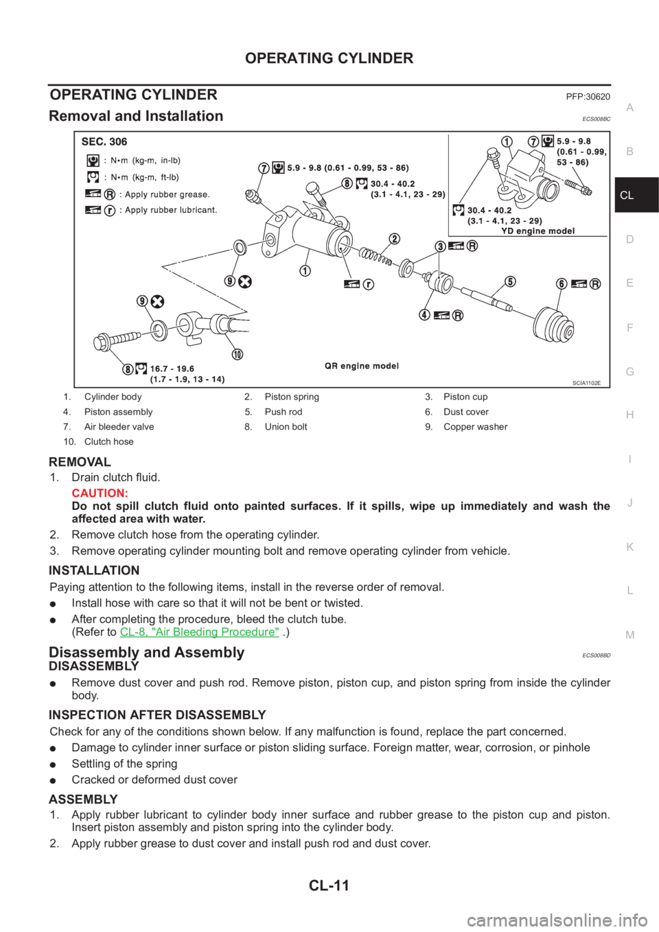
OPERATING CYLINDERPFP:30620
Removal and InstallationECS008BC
REMOVAL
1. Drain clutch fluid.
CAUTION:
Do not spill clutch fluid onto painted surfaces. If it spills, wipe up immediately and wash the
affected area with water.
2. Remove clutch hose from the operating cylinder.
3. Remove operating cylinder mounting bolt and remove operating cylinder from vehicle.
INSTALLATION
Paying attention to the following items, install in the reverse order of removal.
●Install hose with care so that it will not be bent or twisted.
●After completing the procedure, bleed the clutch tube.
(Refer to CL-8, "
Air Bleeding Procedure" .)
Disassembly and AssemblyECS008BD
DISASSEMBLY
●Remove dust cover and push rod. Remove piston, piston cup, and piston spring from inside the cylinder
body.
INSPECTION AFTER DISASSEMBLY
Check for any of the conditions shown below. If any malfunction is found, replace the part concerned.
●Damage to cylinder inner surface or piston sliding surface. Foreign matter, wear, corrosion, or pinhole
●Settling of the spring
●Cracked or deformed dust cover
ASSEMBLY
1. Apply rubber lubricant to cylinder body inner surface and rubber grease to the piston cup and piston.
Insert piston assembly and piston spring into the cylinder body.
2. Apply rubber grease to dust cover and install push rod and dust cover.
1. Cylinder body 2. Piston spring 3. Piston cup
4. Piston assembly 5. Push rod 6. Dust cover
7. Air bleeder valve 8. Union bolt 9. Copper washer
10. Clutch hose
SCIA1102E
Page 1979 of 3833

PRECAUTIONS
MT-3
D
E
F
G
H
I
J
K
L
MA
B
MT
PRECAUTIONSPFP:00001
CautionECS008BM
●Do not reuse transaxle oil, once it has been drained.
●Check oil level or replace oil with vehicle on level ground.
●During removal or installation, keep inside of transaxle clear of dust or dirt.
●Check for the correct installation status prior to removal or disassembly. If mating marks are required, be
certain they do not interfere with the function of the parts they are applied to.
●In principle, tighten bolts or nuts gradually in several steps working diagonally from inside to outside. If
tightening sequence is specified, observe it.
●Be careful not to damage sliding surfaces and mating surfaces.
Page 1991 of 3833

TRANSAXLE ASSEMBLY
MT-15
D
E
F
G
H
I
J
K
L
MA
B
MT
TRANSAXLE ASSEMBLYPFP:32010
Removal and InstallationECS008BX
REMOVAL
1. Remove air cleaner, air duct, and battery.
2. Remove the air breather hose.
3. Remove clutch operating cylinder.
CAUTION:
Do not depress clutch pedal during removal procedure.
4. Disconnect control cable from transaxle.
5. Drain gear oil from transaxle.
6. Disconnect PNP switch, back-up lamp switch, and ground harness connectors.
7. Remove exhaust front tube and the drive shaft.
8. Remove transfer.
●Refer to TF-11, "Removal and Installation from Vehicle" .
9. Remove starter motor.
10. Place a jack onto the transaxle.
CAUTION:
When setting jack, be careful not to bring it into contact with the switch.
11. Remove center member, engine insulator and engine mount bracket.
●Refer to EM-69, "ENGINE ASSEMBLY" (QR engine models) or EM-193, "ENGINE ASSEMBLY" (YD
engine models).
12. Remove suspension members.
●Refer to FSU-12, "FRONT SUSPENSION MEMBER" .
13. Support engine by placing a jack under oil pan.
14. Remove bolts securing transaxle to engine.
SCIA0845E
Page 2002 of 3833
MT-26
TRANSAXLE ASSEMBLY
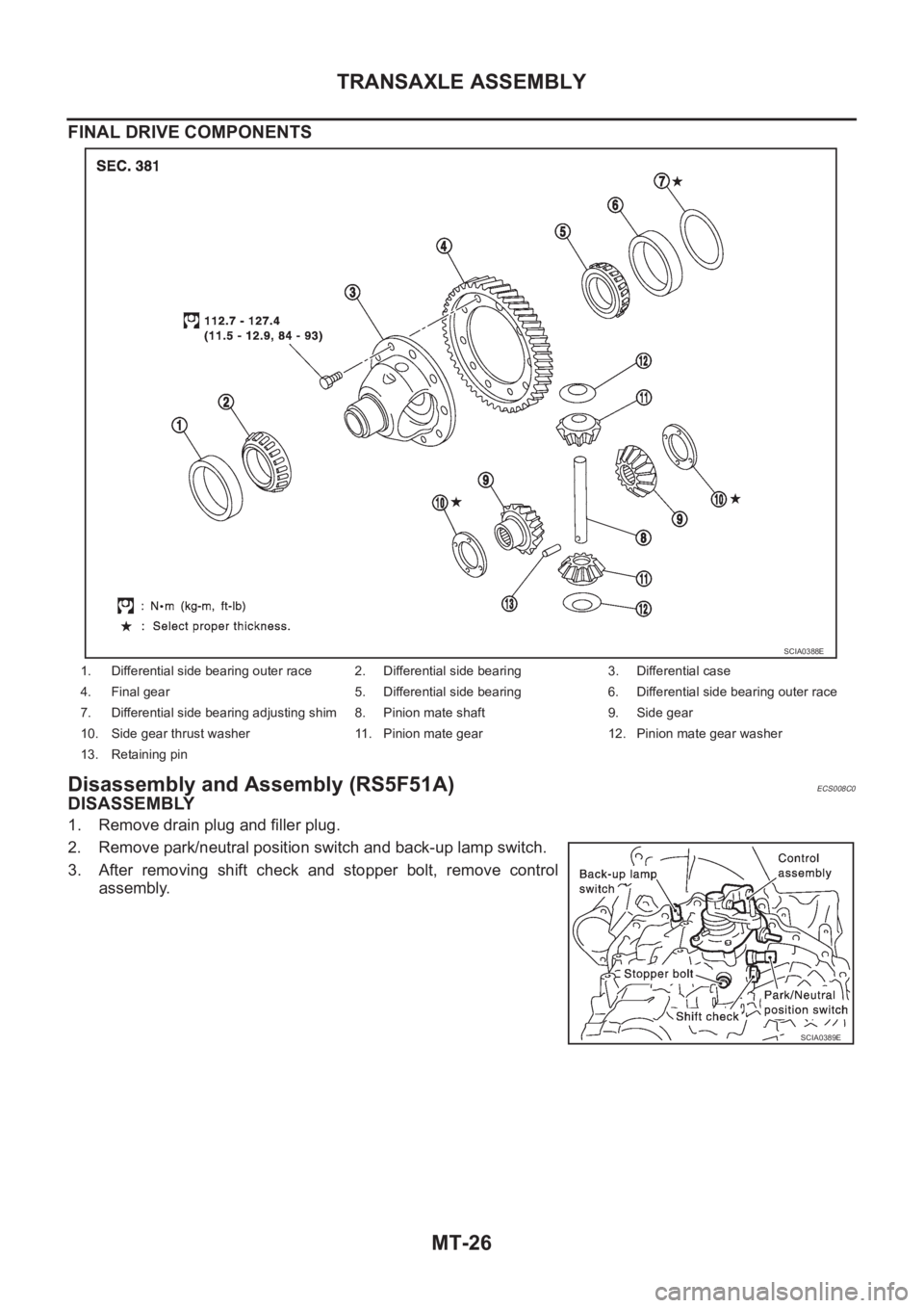
FINAL DRIVE COMPONENTS
Disassembly and Assembly (RS5F51A)ECS008C0
DISASSEMBLY
1. Remove drain plug and filler plug.
2. Remove park/neutral position switch and back-up lamp switch.
3. After removing shift check and stopper bolt, remove control
assembly.
1. Differential side bearing outer race 2. Differential side bearing 3. Differential case
4. Final gear 5. Differential side bearing 6. Differential side bearing outer race
7. Differential side bearing adjusting shim 8. Pinion mate shaft 9.Side gear
10. Side gear thrust washer 11. Pinion mate gear 12. Pinion mate gear washer
13. Retaining pin
SCIA0388E
SCIA0389E
Page 2011 of 3833
TRANSAXLE ASSEMBLY
MT-35
D
E
F
G
H
I
J
K
L
MA
B
MT
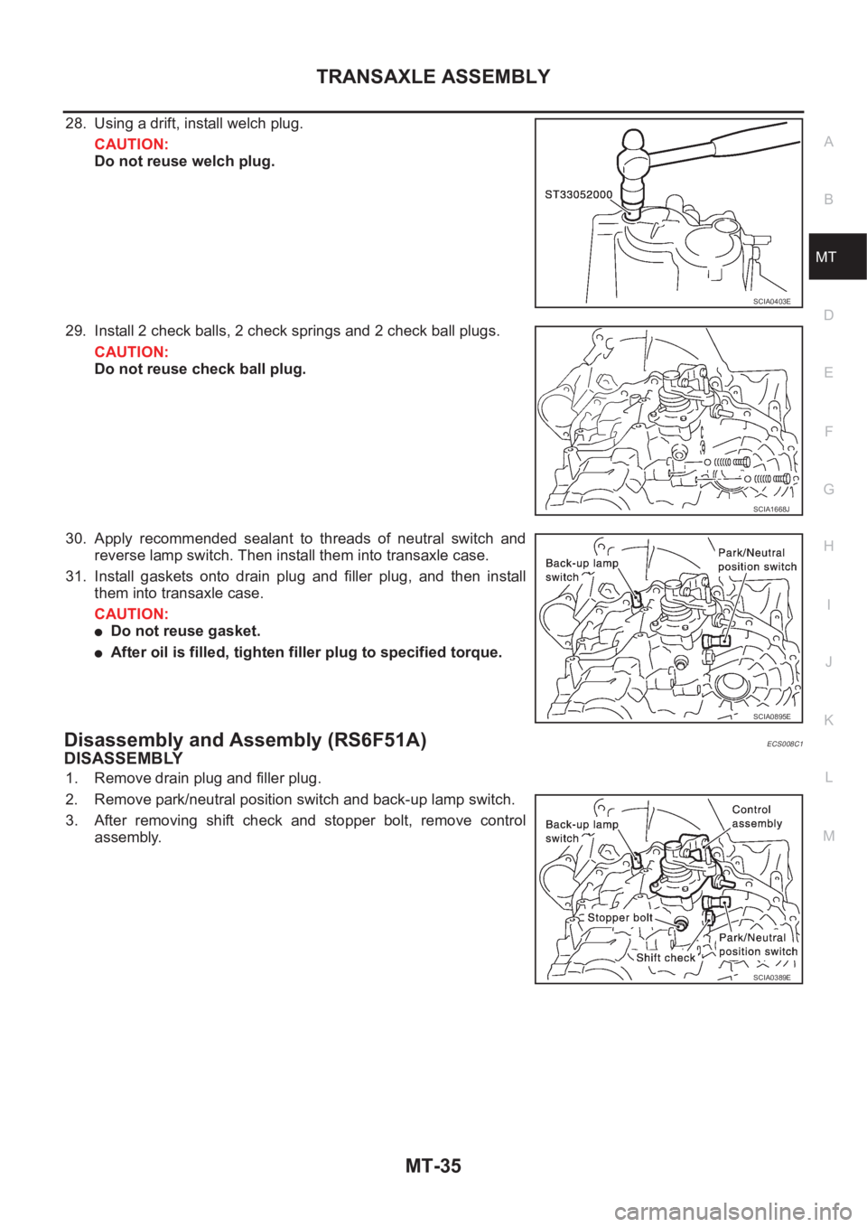
28. Using a drift, install welch plug.
CAUTION:
Do not reuse welch plug.
29. Install 2 check balls, 2 check springs and 2 check ball plugs.
CAUTION:
Do not reuse check ball plug.
30. Apply recommended sealant to threads of neutral switch and
reverse lamp switch. Then install them into transaxle case.
31. Install gaskets onto drain plug and filler plug, and then install
them into transaxle case.
CAUTION:
●Do not reuse gasket.
●After oil is filled, tighten filler plug to specified torque.
Disassembly and Assembly (RS6F51A)ECS008C1
DISASSEMBLY
1. Remove drain plug and filler plug.
2. Remove park/neutral position switch and back-up lamp switch.
3. After removing shift check and stopper bolt, remove control
assembly.
SCIA0403E
SCIA1668J
SCIA0895E
SCIA0389E
Page 2020 of 3833
MT-44
TRANSAXLE ASSEMBLY
CAUTION:
Do not reuse the O-ring.
i. Install shift check and stopper bolt.
CAUTION:
Does not reuse shift check and stopper bolt.
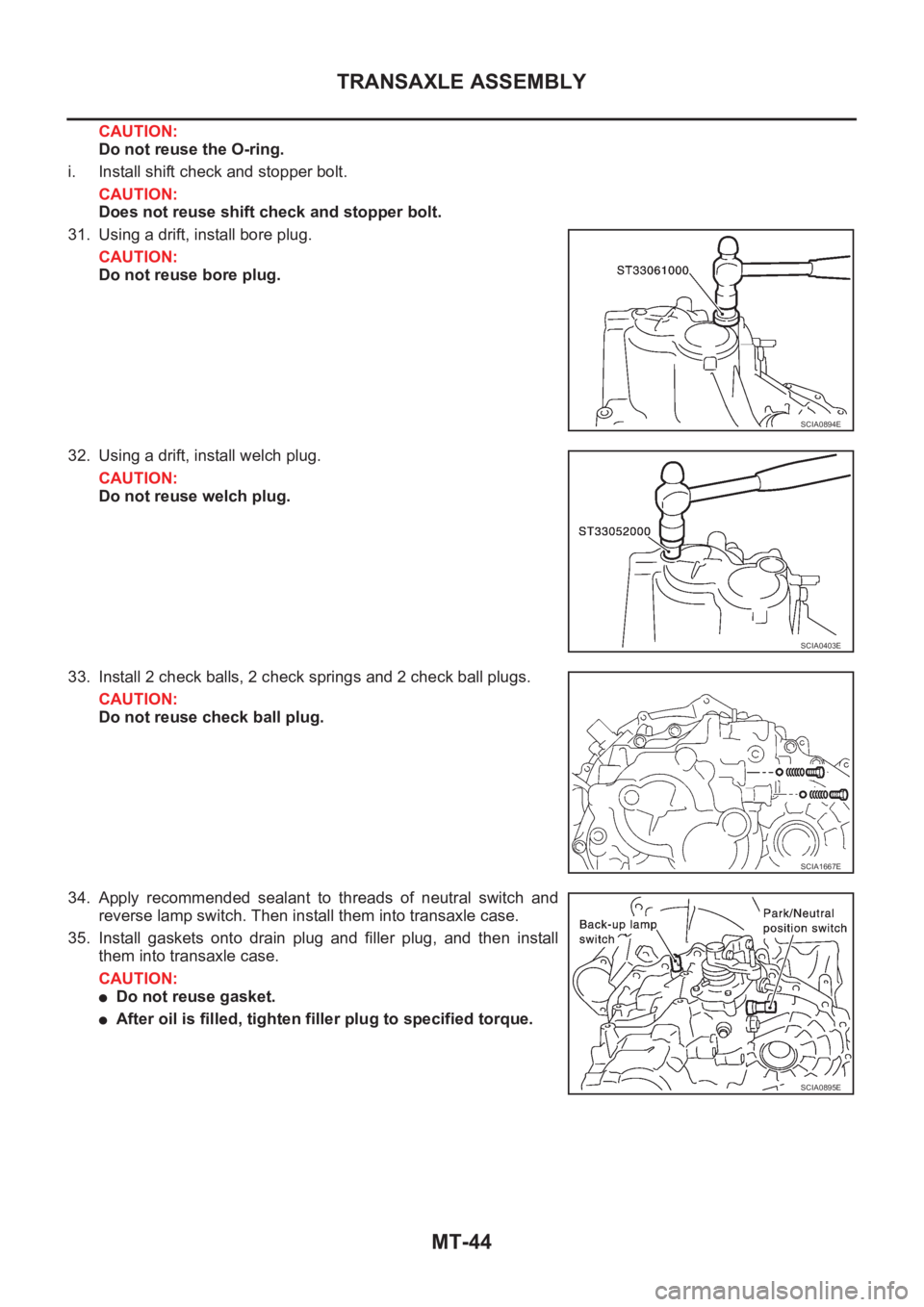
31. Using a drift, install bore plug.
CAUTION:
Do not reuse bore plug.
32. Using a drift, install welch plug.
CAUTION:
Do not reuse welch plug.
33. Install 2 check balls, 2 check springs and 2 check ball plugs.
CAUTION:
Do not reuse check ball plug.
34. Apply recommended sealant to threads of neutral switch and
reverse lamp switch. Then install them into transaxle case.
35. Install gaskets onto drain plug and filler plug, and then install
them into transaxle case.
CAUTION:
●Do not reuse gasket.
●After oil is filled, tighten filler plug to specified torque.
SCIA0894E
SCIA0403E
SCIA1667E
SCIA0895E
Page 2596 of 3833

AT-518
[ALL]
ASSEMBLY
d. Pass solenoid harness through transmission case and install
terminal body on transmission case by pushing it.
e. Install stopper ring to terminal body.
f. Tighten bolts I , X and
●.
Bolt length, number and location:
18. Install oil pan.
a. Attach a magnet to oil pan.
b. Install new oil pan gasket on transmission case.
c. Install oil pan on transmission case.
●Always replace oil pan bolts as they are self-sealing
bolts.
●Tighten four bolts in a criss-cross pattern to prevent dis-
location of gasket.
d. Tighten oil pan bolts and drain plug to the specified torque.
Refer to AT- 4 2 1 , "
OVERHAUL" .
SCIA0808E
BoltIX●
Bolt length “ ” mm (in)40 (1.57) 33 (1.30)43.5
(1.713)
Number of bolts 5 6 2
SAT004F
SAT003F
Page 2597 of 3833

ASSEMBLY
AT-519
[ALL]
D
E
F
G
H
I
J
K
L
MA
B
AT
19. Install park/neutral position (PNP) switch.
a. Set manual shaft in P position.
b. Temporarily install park/neutral position (PNP) switch on manual
shaft.
c. Move selector lever to N position.
d. Use a 4 mm (0.16 in) pin for this adjustment.
i. Insert the pin straight into the manual shaft adjustment hole.
ii. Rotate park/neutral position (PNP) switch until the pin can also
be inserted straight into hole in park/neutral position (PNP)
switch.
e. Tighten park/neutral position (PNP) switch fixing bolts. Refer to
AT- 4 2 1 , "
OVERHAUL" .
f. Remove pin from adjustment hole after adjusting park/neutral
position (PNP) switch.
20. Install A/T fluid charging pipe and fluid cooler tube to transmis-
sion case. Tighten A/T fluid charging pipe and fluid cooler tube
bolts to the specified torque. Refer to AT-421, "
OVERHAUL" .
21. Install torque converter.
a. Pour ATF into torque converter.
●Approximately 1 liter (1-1/8 US qt, 7/8 Imp qt) of fluid is
required for a new torque converter.
●When reusing old torque converter, add the same amount
of fluid as was drained.
b. Install torque converter while aligning notches of torque con-
verter with notches of oil pump.
SAT033J
AAT469A
SAT768J
SAT428DA
SAT429D
Page 2613 of 3833
PRECAUTIONS
TF-3
C
E
F
G
H
I
J
K
L
MA
B
TF
PRECAUTIONSPFP:00001
CautionEDS0004O
●Do not reuse the drained transfer oil.
●Check the oil level with the vehicle on the level ground.
●During removal and installation, be careful not to allow foreign material such as dust or dirt to enter into
the transfer unit.
●Before starting diagnosis of the vehicle, understand trouble symptoms well. Perform correct and system-
atic operations.
●Check for the correct installation status prior to removal or disassembly. If mating marks are required, be
certain they do not interfere with the function of the parts they are applied to.
●Carry out the work in a clean work place. Using a dust proof room is recommended.
●Before disassembly, using steam or white gasoline, completely remove sand and mud from the exterior of
the unit, preventing them from entering into the unit during disassembly or assembly.
●Check appearance of the disassembled parts for damage, deformation, and abnormal wear. If a malfunc-
tion is detected, replace it with a new one.
●Normally replace O-rings, oil seals, bearings, and lock nuts with new ones every time they are removed.
●In principle, tighten bolts or nuts gradually in several steps working diagonally from inside to outside. If
tightening sequence is specified, observe it.
●Clean and flush the parts sufficiently and blow them dry.
●Be careful not to damage sliding surfaces and mating surfaces.
●Always use shop paper for cleaning the inside of components.
●Do not use cotton gloves or a shop cloth. Using them may leave lint on the surface of the parts.
●During assembly always tighten bolts and screws to specified torque. New transfer oil a petroleum jelly
such as "Vaseline", or multi-purpose grease as appropriate.
●Discard waste oil after oil changes or part treatment in accordance with local laws and regulations.
Page 2637 of 3833

TRANSFER ASSEMBLY
TF-27
C
E
F
G
H
I
J
K
L
MA
B
TF
Adapter case
1. Select the adjusting shim on the gear ring bearing.
●TF-23, "SELECTIONG ADJUSTING SHIMS".
2. Install the oil gutter.
3. Using a drift, install the selected adjusting shim and gear ring
bearing outer race to the adapter case.
4. Using a drift, drive the oil seal until it becomes flush with the
case end.
CAUTION:
●When checking the overall preload torque, measure it
without the oil seal, then install the oil seal.
●Discard old oil seals; replace with new ones.
●Apply multi-purpose grease onto oil seal lips, and gear
oil onto the circumference of the oil seal.
5. Apply recommended sealant on drain plug and install it to the
adapter case.
6. Apply multi-purpose grease lightly and evenly onto an O-ring, and install it to the adapter case.
CAUTION:
Do not reuse the O-ring.
7. Install the adapter case to the transfer case, and apply anti-cor-
rosive oil onto threads and seats on the mounting bolts. Tighten
to the specified torque.
8. Check backlash, preload torque, tooth contact, and companion
flange runout.
●TF-14, "Assembly Inspection".
CAUTION:
Measure the overall preload torque without the oil seal.
Pinion sleeve assembly
1. Select the pinion sleeve shim.
●TF-23, "SELECTIONG ADJUSTING SHIMS".
SDIA0545E
Drain plug tightening torque
: 9.8 - 19.6 N·m (1.0 -1.9 kg-m, 87 - 173 in-lb)
Tightening torque
: 14 - 16 N·m (1.4 -1.7 kg-m, 11 - 12 ft-lb)
SDIA0546E
SDIA0547E