4WD NISSAN X-TRAIL 2001 Service Service Manual
[x] Cancel search | Manufacturer: NISSAN, Model Year: 2001, Model line: X-TRAIL, Model: NISSAN X-TRAIL 2001Pages: 3833, PDF Size: 39.49 MB
Page 2662 of 3833
TF-52
TROUBLE DIAGNOSIS
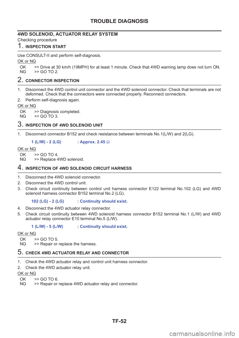
4WD SOLENOID, ACTUATOR RELAY SYSTEM
Checking procedure
1. INSPECTION START
Use CONSULT-II and perform self-diagnosis.
OK or NG
OK >> Drive at 30 km/h (19MPH) for at least 1 minute. Check that 4WD warning lamp does not turn ON.
NG >> GO TO 2.
2. CONNECTOR INSPECTION
1. Disconnect the 4WD control unit connector and the 4WD solenoid connector. Check that terminals are not
deformed. Check that the connectors were connected properly. Reconnect connectors.
2. Perform self-diagnosis again.
OK or NG
OK >> Diagnosis completed.
NG >> GO TO 3.
3. INSPECTION OF 4WD SOLENOID UNIT
1. Disconnect connector B152 and check resistance between terminals No.1(L/W) and 2(LG).
OK or NG
OK >> GO TO 4.
NG >> Replace 4WD solenoid.
4. INSPECTION OF 4WD SOLENOID CIRCUIT HARNESS
1. Disconnect the 4WD solenoid connector.
2. Disconnect the 4WD control unit.
3. Check circuit continuity between control unit harness connector E122 terminal No.102 (LG) and 4WD
solenoid harness connector B152 terminal No.2 (LG).
4. Disconnect the 4WD actuator relay connector.
5. Check circuit continuity between 4WD solenoid harness connector B152 terminal No.1 (L/W) and 4WD
actuator relay connector E10 terminal No.5 (L/W).
OK or NG
OK >> GO TO 5.
NG >> Repair or replace the harness.
5. CHECK 4WD ACTUATOR RELAY AND CONNECTOR
1. Check the 4WD actuator relay and control unit harness connector.
2. Check the 4WD actuator relay unit.
OK or NG
OK >> GO TO 6.
NG >> Repair or replace 4WD actuator relay and connector.1 (L/W) - 2 (LG) : Approx. 2.45 Ω
102 (LG) - 2 (LG) : Continuity should exist.
1 (L/W) - 5 (L/W) : Continuity should exist.
Page 2663 of 3833
TROUBLE DIAGNOSIS
TF-53
C
E
F
G
H
I
J
K
L
MA
B
TF
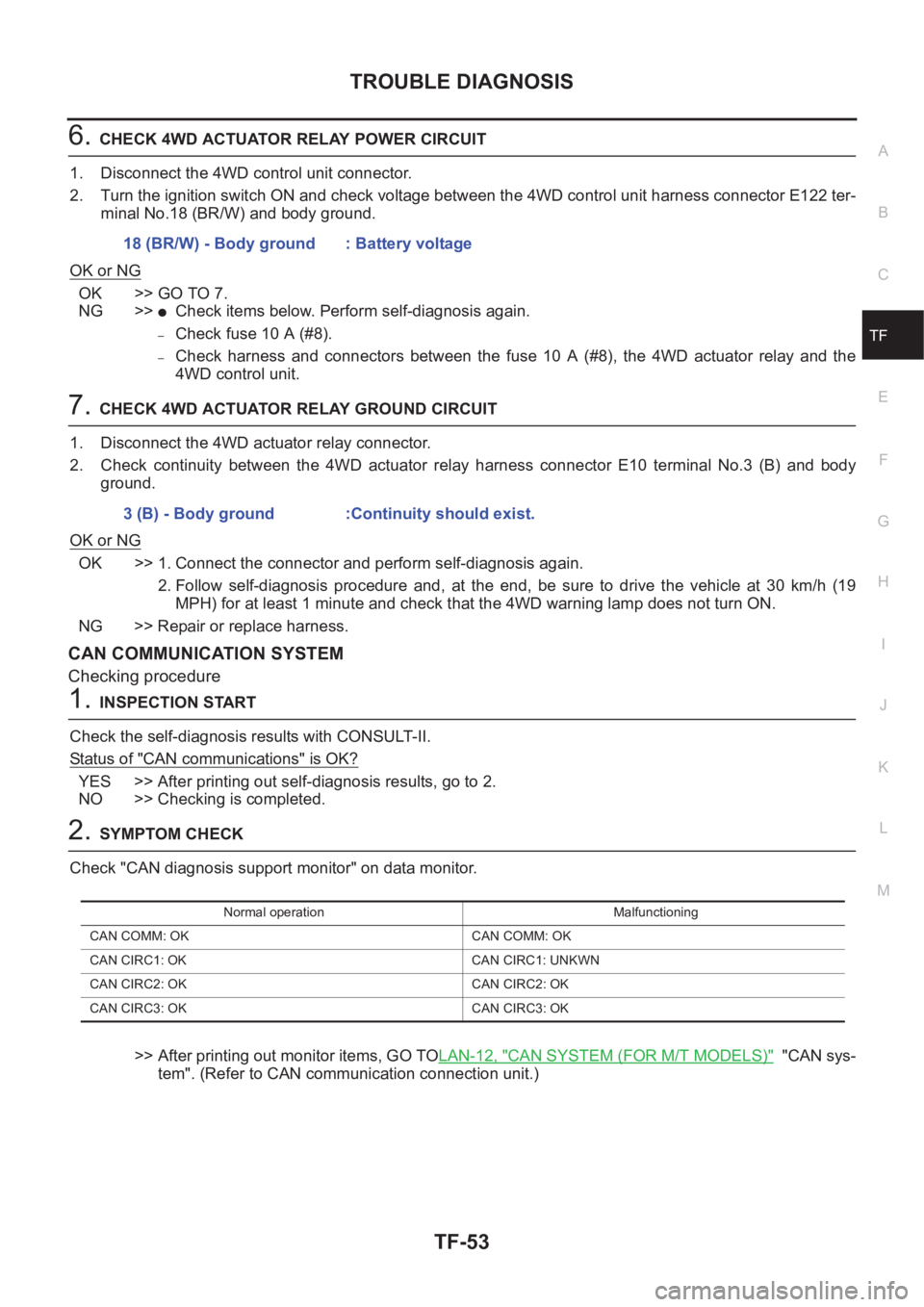
6.CHECK 4WD ACTUATOR RELAY POWER CIRCUIT
1. Disconnect the 4WD control unit connector.
2. Turn the ignition switch ON and check voltage between the 4WD control unit harness connector E122 ter-
minal No.18 (BR/W) and body ground.
OK or NG
OK >> GO TO 7.
NG >>
●Check items below. Perform self-diagnosis again.
–Check fuse 10 A (#8).
–Check harness and connectors between the fuse 10 A (#8), the 4WD actuator relay and the
4WD control unit.
7.CHECK 4WD ACTUATOR RELAY GROUND CIRCUIT
1. Disconnect the 4WD actuator relay connector.
2. Check continuity between the 4WD actuator relay harness connector E10 terminal No.3 (B) and body
ground.
OK or NG
OK >> 1. Connect the connector and perform self-diagnosis again.
2. Follow self-diagnosis procedure and, at the end, be sure to drive the vehicle at 30 km/h (19
MPH) for at least 1 minute and check that the 4WD warning lamp does not turn ON.
NG >> Repair or replace harness.
CAN COMMUNICATION SYSTEM
Checking procedure
1.INSPECTION START
Check the self-diagnosis results with CONSULT-II.
Status of "CAN communications" is OK?
YES >> After printing out self-diagnosis results, go to 2.
NO >> Checking is completed.
2.SYMPTOM CHECK
Check "CAN diagnosis support monitor" on data monitor.
>> After printing out monitor items, GO TOLAN-12, "
CAN SYSTEM (FOR M/T MODELS)" "CAN sys-
tem". (Refer to CAN communication connection unit.) 18 (BR/W) - Body ground : Battery voltage
3 (B) - Body ground :Continuity should exist.
Normal operation Malfunctioning
CAN COMM: OK CAN COMM: OK
CAN CIRC1: OK CAN CIRC1: UNKWN
CAN CIRC2: OK CAN CIRC2: OK
CAN CIRC3: OK CAN CIRC3: OK
Page 2664 of 3833
TF-54
TROUBLE DIAGNOSIS
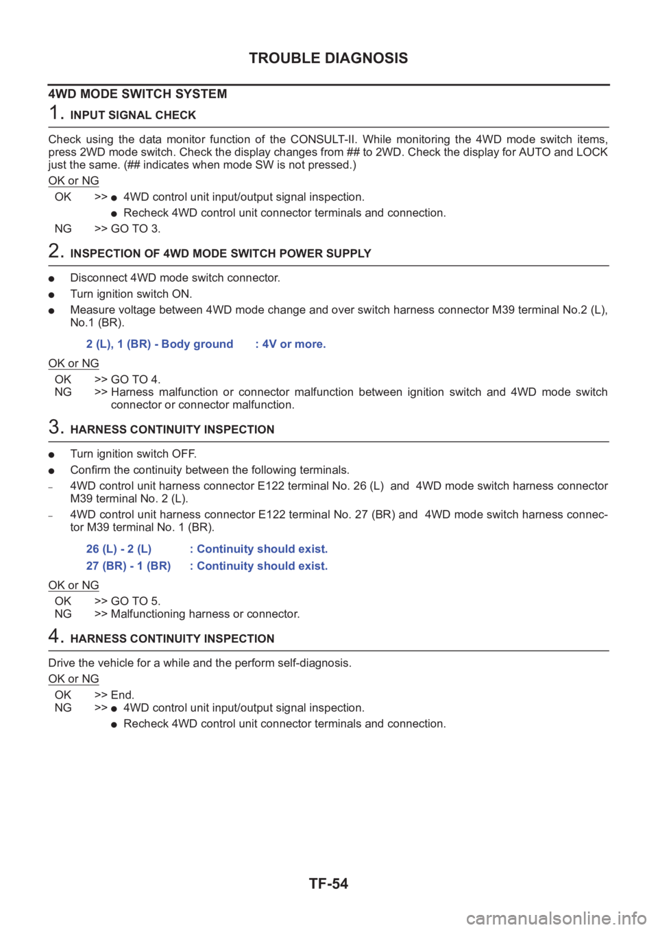
4WD MODE SWITCH SYSTEM
1. INPUT SIGNAL CHECK
Check using the data monitor function of the CONSULT-II. While monitoring the 4WD mode switch items,
press 2WD mode switch. Check the display changes from ## to 2WD. Check the display for AUTO and LOCK
just the same. (## indicates when mode SW is not pressed.)
OK or NG
OK >>●4WD control unit input/output signal inspection.
●Recheck 4WD control unit connector terminals and connection.
NG >> GO TO 3.
2. INSPECTION OF 4WD MODE SWITCH POWER SUPPLY
●Disconnect 4WD mode switch connector.
●Turn ignition switch ON.
●Measure voltage between 4WD mode change and over switch harness connector M39 terminal No.2 (L),
No.1 (BR).
OK or NG
OK >> GO TO 4.
NG >> Harness malfunction or connector malfunction between ignition switch and 4WD mode switch
connector or connector malfunction.
3. HARNESS CONTINUITY INSPECTION
●Turn ignition switch OFF.
●Confirm the continuity between the following terminals.
–4WD control unit harness connector E122 terminal No. 26 (L) and 4WD mode switch harness connector
M39 terminal No. 2 (L).
–4WD control unit harness connector E122 terminal No. 27 (BR) and 4WD mode switch harness connec-
tor M39 terminal No. 1 (BR).
OK or NG
OK >> GO TO 5.
NG >> Malfunctioning harness or connector.
4. HARNESS CONTINUITY INSPECTION
Drive the vehicle for a while and the perform self-diagnosis.
OK or NG
OK >> End.
NG >>
●4WD control unit input/output signal inspection.
●Recheck 4WD control unit connector terminals and connection. 2 (L), 1 (BR) - Body ground : 4V or more.
26 (L) - 2 (L) : Continuity should exist.
27 (BR) - 1 (BR) : Continuity should exist.
Page 2665 of 3833
TROUBLE DIAGNOSIS
TF-55
C
E
F
G
H
I
J
K
L
MA
B
TF
Trouble Diagnoses for SymptomsEDS000IS
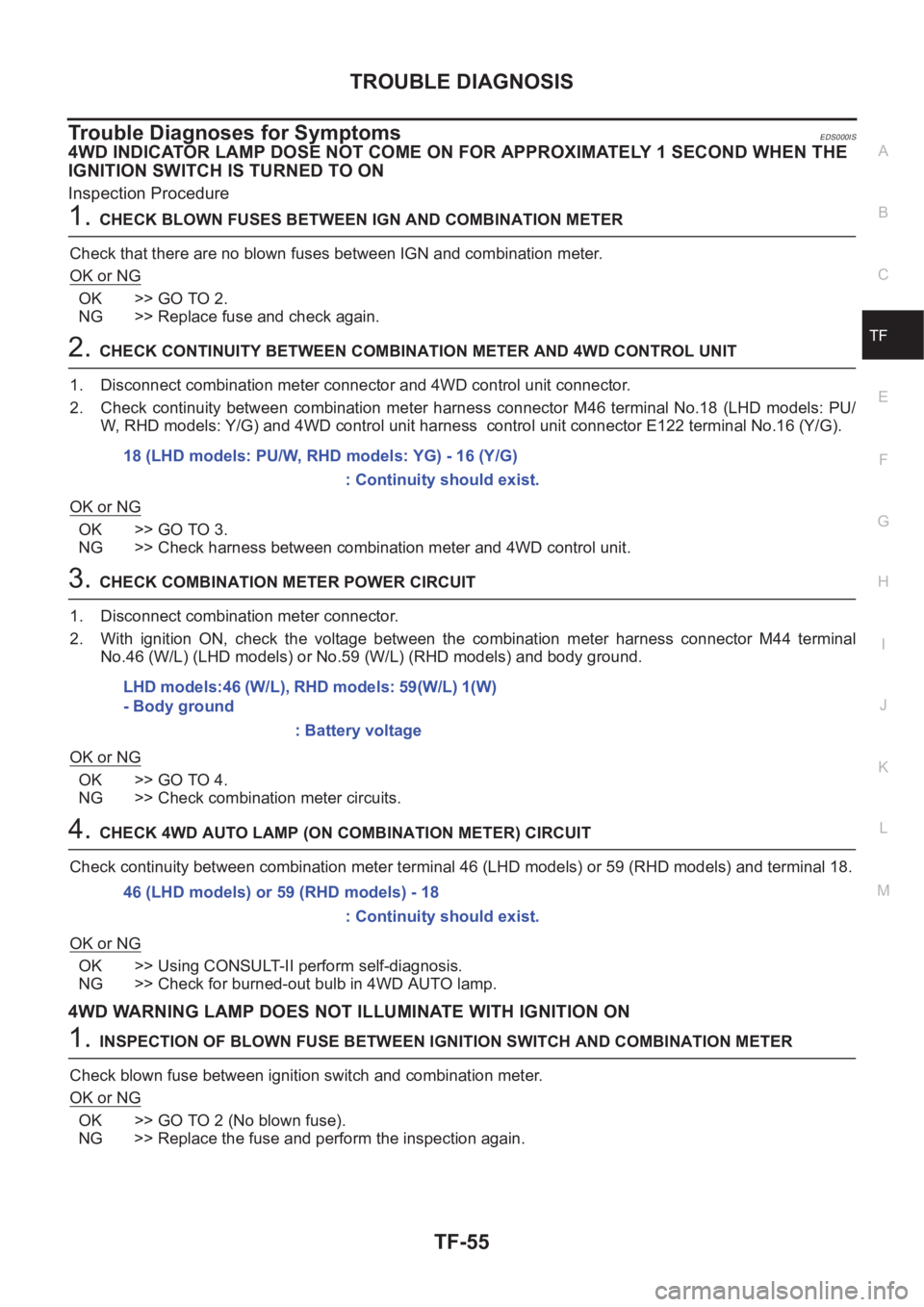
4WD INDICATOR LAMP DOSE NOT COME ON FOR APPROXIMATELY 1 SECOND WHEN THE
IGNITION SWITCH IS TURNED TO ON
Inspection Procedure
1.CHECK BLOWN FUSES BETWEEN IGN AND COMBINATION METER
Check that there are no blown fuses between IGN and combination meter.
OK or NG
OK >> GO TO 2.
NG >> Replace fuse and check again.
2.CHECK CONTINUITY BETWEEN COMBINATION METER AND 4WD CONTROL UNIT
1. Disconnect combination meter connector and 4WD control unit connector.
2. Check continuity between combination meter harness connector M46 terminal No.18 (LHD models: PU/
W, RHD models: Y/G) and 4WD control unit harness control unit connector E122 terminal No.16 (Y/G).
OK or NG
OK >> GO TO 3.
NG >> Check harness between combination meter and 4WD control unit.
3.CHECK COMBINATION METER POWER CIRCUIT
1. Disconnect combination meter connector.
2. With ignition ON, check the voltage between the combination meter harness connector M44 terminal
No.46 (W/L) (LHD models) or No.59 (W/L) (RHD models) and body ground.
OK or NG
OK >> GO TO 4.
NG >> Check combination meter circuits.
4.CHECK 4WD AUTO LAMP (ON COMBINATION METER) CIRCUIT
Check continuity between combination meter terminal 46 (LHD models) or 59 (RHD models) and terminal 18.
OK or NG
OK >> Using CONSULT-II perform self-diagnosis.
NG >> Check for burned-out bulb in 4WD AUTO lamp.
4WD WARNING LAMP DOES NOT ILLUMINATE WITH IGNITION ON
1.INSPECTION OF BLOWN FUSE BETWEEN IGNITION SWITCH AND COMBINATION METER
Check blown fuse between ignition switch and combination meter.
OK or NG
OK >> GO TO 2 (No blown fuse).
NG >> Replace the fuse and perform the inspection again.18 (LHD models: PU/W, RHD models: YG) - 16 (Y/G)
: Continuity should exist.
LHD models:46 (W/L), RHD models: 59(W/L) 1(W)
- Body ground
: Battery voltage
46 (LHD models) or 59 (RHD models) - 18
: Continuity should exist.
Page 2666 of 3833
TF-56
TROUBLE DIAGNOSIS
2. COMBINATION METER POWER SUPPLY CIRCUIT INSPECTION
1. Disconnect combination meter connector.
2. Check voltage between the combination meter harness connector M46 terminal No. LHD models: 46 (W/
L) RHD models: 59 (W/L) and body ground.
OK or NG
OK >> Malfunctioning combination meter.
NG >> Check fuse 10A [#11] to combination meter harness and connector.
4WD WARNING LAMP DOES NOT GO OUT SEVERAL SECONDS AFTER ENGINE
STARTED.(4WD MODE INDICATOR LAMP GOES OUT)
1. PERFORM SELF-DIAGNOSIS
Using CONSULT-II perform self-diagnosis.
OK or NG
OK >> No malfunction detected. Perform inspection again.
NG >>
●Determine the location of the malfunction according to the result of Self-diagnosis using CON-
SULT-II. (Malfunction is present in the 4WD system.)
●CONSULT-II does not display 4WD system-related trouble codes. GO TO 2.
2. 4WD CONTROL UNIT CONNECTOR CONNECTION INSPECTION
●Check 4WD control unit connector for proper connection.
OK or NG
OK >> Reconnect the 4WD control unit connector properly and perform inspection again.
NG >> Repair or replace the connector.
HEAVY TIGHT-CORNER BRAKING SYMPTOM OCCURS WHEN THE VEHICLE IS DRIVEN IN
AUTO MODE AND THE STEERING WHEEL IS TURNED FULLY TO EITHER SIDE AFTER THE
ENGINE IS STARTED
1. PERFORM SELF-DIAGNOSIS.
Using CONSULT-II perform self-diagnosis.
OK or NG
OK >> GO TO 2. (No self-diagnosis malfunction indicated.)
NG >> Determine the location of the malfunction according to the result of self-diagnosis using CON-
SULT-II. (Malfunction is present in the 4WD system.)
2. CHECK USING THE DATA MONITOR FUNCTION OF THE CONSULT- II.
●Perform inspection by the data monitor function of the CONSULT-II.
●Check that the operation is in AUTO mode.
●Measure voltage when the accelerator pedal is not depressed. (Accelerator pedal not depressed: approx.
0.5V or lower)
●Measure the current supplied to the 4WD solenoid valve. (Accelerator pedal not depressed: approx. 0A)
OK or NG
OK >> GO TO 3. (No self-diagnosis malfunction indicated.)
NG >>
●Not in AUTO mode. GO TO 3.
●Voltage when accelerator pedal is not depressed is higher than approximately 0.5V.
●4WD solenoid valve current when the accelerator pedal is not depressed is other than 0A.
●Countermeasure: Keep the vehicle idling for approximately 15 minutes before checking again.
(Voltage when accelerator pedal is not depressed will be automatically reset to zero during this
period.)
Page 2667 of 3833
TROUBLE DIAGNOSIS
TF-57
C
E
F
G
H
I
J
K
L
MA
B
TF
3.INSPECTION USING 4WD MODE CHANGE-OVER SWITCH
●On data monitor screen of the CONSULT-II, check 4WD mode switch.
●Check if the display changes from ## to 2WD mode when the 2WD switch is pressed.
●Check if the display changes from ## to AUTO mode when the AUTO switch is pressed.
●Check if the display changes from ## to LOCK mode when the LOCK switch is pressed.
OK or NG
OK >> No malfunction detected.
NG >>
●Not in AUTO mode. (In 2WD or LOCK mode)
Countermeasure: Slightly depress the accelerator pedal and check that the operation mode
changes to LOCK mode.
●Check circuit between 4WD mode switch harness connector M39 terminal No.1 (BR) and
4WD control unit harness connector E122 terminal No. 27 (BR).
(AUTO mode is not available because a malfunction is present in the 2WD mode harness.)
NOTICE:
Mechanism of 4WD mode change-over.
●2WD mode: Operation changes to 2WD mode when 4WD control unit harness connector E122
terminal No. 27 (BR) is shorted to ground.
●AUTO mode: Operation changes to AUTO mode when 4WD control unit harness connector
E122 terminals No. 27 (BR) and No. 26 (L) is shorted to ground.
●LOCK mode: Operation changes to LOCK mode when 4WD control unit harness connector
E122 terminal No. 26 (L) is shorted to ground.
4WD MODES CANNOT BE SWITCHED AFTER ENGINE IS STARTED
1.INSPECTION USING 4WD MODE CHANGE-OVER SWITCH
●Drive modes cannot be switched after the engine is started.
●On data monitor screen of the CONSULT-II, check 4WD mode switch.
●Check if the display changes from ## to 2WD mode when the 2WD switch is pressed.
●Check if the display changes from ## to AUTO mode when the AUTO switch is pressed.
●Check if the display changes from ## to LOCK mode when the LOCK switch is pressed.
OK or NG
OK >> No malfunction detected.
NG >>
●CONSULT-II display does not change from ## when the 2WD switch is pressed. Check harness
of the 2WD switch.
●CONSULT-II display does not change from ## when the AUTO switch is pressed. Check har-
ness of the 2WD switch and LOCK switch.
●CONSULT-II display does not change from ## when the LOCK switch is pressed. Check har-
ness of the LOCK switch.
●Perform 4WD mode change-over switch inspection.
WHILE DRIVING, 4WD WARNING LAMP FLASHES RAPIDLY. (WHEN IT FLASHERS FOR
APPROX. ONE MINUTE, THEN DOES NOT ILLUMINATE.)
●While driving, 4WD warning lamp flashes rapidly. (when it flashes for approx. one minute, then does not
illuminate.)
Rapid flashing: 2 times/second
This phenomenon protects drivetrain parts when a heavy load is applied to the electronically controlled
coupling and multiple disc clutch temperature increases. It is not a malfunction.
When the difference of diameters by or with the front and rear wheel with AUTO mode the shift switch
occasionally changes to LOCK mode automatically. This is not a malfunction.
When the difference of revolution speed between the front and rear wheel with AUTO mode, the shift
switch occasionally changes to LOCK mode automatically. This is not a malfunction.
WHILE DRIVING, 4WD WARNING LAMP FLASHES SLOWLY. (WHEN IT CONTINUES TO ILLU-
MINATE UNTIL ENGINE TURNS OFF.)
1. Check using the data monitor function of the CONSULT-II.
Page 2668 of 3833
TF-58
TROUBLE DIAGNOSIS
●Perform inspection with the data monitor function of the CONSULT- I I .
●Check if the value of IMPROPER SIZE TIRE MONITOR is 8 mm (0.31 in) or more.
●Stop the engine. Restart the engine and drive the vehicle at 20 km/h (12 MPH) or faster for approxi-
mately 200 seconds. Confirm the 4WD warning lamp flashes slowly.
(Check if the value of IMPROPER SIZE TIRE MONITOR is 8 mm (0.31 in) or more.)
When the tire size is normal, the value of IMPROPER SIZE TIRE MONITOR will change from 8 mm
(0.31 in) or more to 0 to 4 mm (0 to 0.16 in) (normal condition) after the vehicle is driven 20 km/h (12
MPH) or faster for approximately 5 seconds.
2. Tire inspection
●Inspection of tire pressure.
●Wear condition.
●Check size of the front and rear tires. (No excessive difference should be observed.)
VEHICLE DOES NOT ENTER 4WD MODE EVEN THOUGH 4WD WARNING LAMP IS OFF.
1. Check using the data monitor function of the CONSULT-II.
Perform inspection by the data monitor function of the CONSULT-II.
–Check if the vehicle operation changes to 2WD, AUTO, and LOCK modes.
–Check current supplied to the 4WD solenoid valve in AUTO mode.
2. Check using the active test function of the CONSULT-II.
Using active test mode of CONSULT-II, supply current to the 4WD solenoid valve and check that the mon-
itor current becomes close to this supply current.
●The 4WDcontrol unit is normal when the difference between 4WD solenoid valve current and the monitor
current is within ±10%.
It is necessary to inspect the electronically controlled coupling assembly.
TIGHT-CONER BRAKING SYMPTOM OCCURS WHEN THE VEHICLE IS STARTED IN AUTO
WARNING LAMP REMAIN OFF).
1. THROTTLE POSITION SENSOR AND HARNESS INSPECTION
Check accelerator pedal stroke.
OK or NG
OK >> Perform self-diagnosis again.
NG >> Malfunctioning throttle position sensor harness.
4WD ACTUATOR RELAY (4WD SOLENOID ACTUATOR RELAY) TURNS ON/OFF FREQUENTLY
1. SELF-DIAGNOSIS RESULT IS 4WD ACTUATOR RELAY (4WD SOLENOID ACTUATOR RELAY) ON
ERROR AND OFF ERROR.
Is self-diagnosis result [ON error and OFF error]?
OK or NG
OK >> GO TO 2.
NG >> Repair or replace as necessary.
2. 4WD ACTUATOR RELAY (4WD SOLENOID ACTUATOR RELAY) AND HARNESS INSPECTION
Is self-diagnosis result [ON error and OFF error]?
OK or NG
OK >> Perform self-diagnosis again.
NG >> Malfunctioning 4WD actuator relay (4WD solenoid actuator relay) harness. Accelerator pedal not
depressed:Approx. 0A
Accelerator pedal
depressed:Approx. 2.8A
Example) Monitor value becomes approx. 1A for 4WD solenoid current 1A setting.
Page 2719 of 3833
SERVICE DATA AND SPECIFICATIONS (SDS)
FSU-13
C
D
F
G
H
I
J
K
L
MA
B
FSU
SERVICE DATA AND SPECIFICATIONS (SDS)PFP:00030
General SpecificationEES000J6
Wheel Alignment (Unladen)EES00079
: Fuel, radiator coolant and engine oil full. Spare tire, jack, hand tools and mats in designated positions.
Ball JointEES0007A
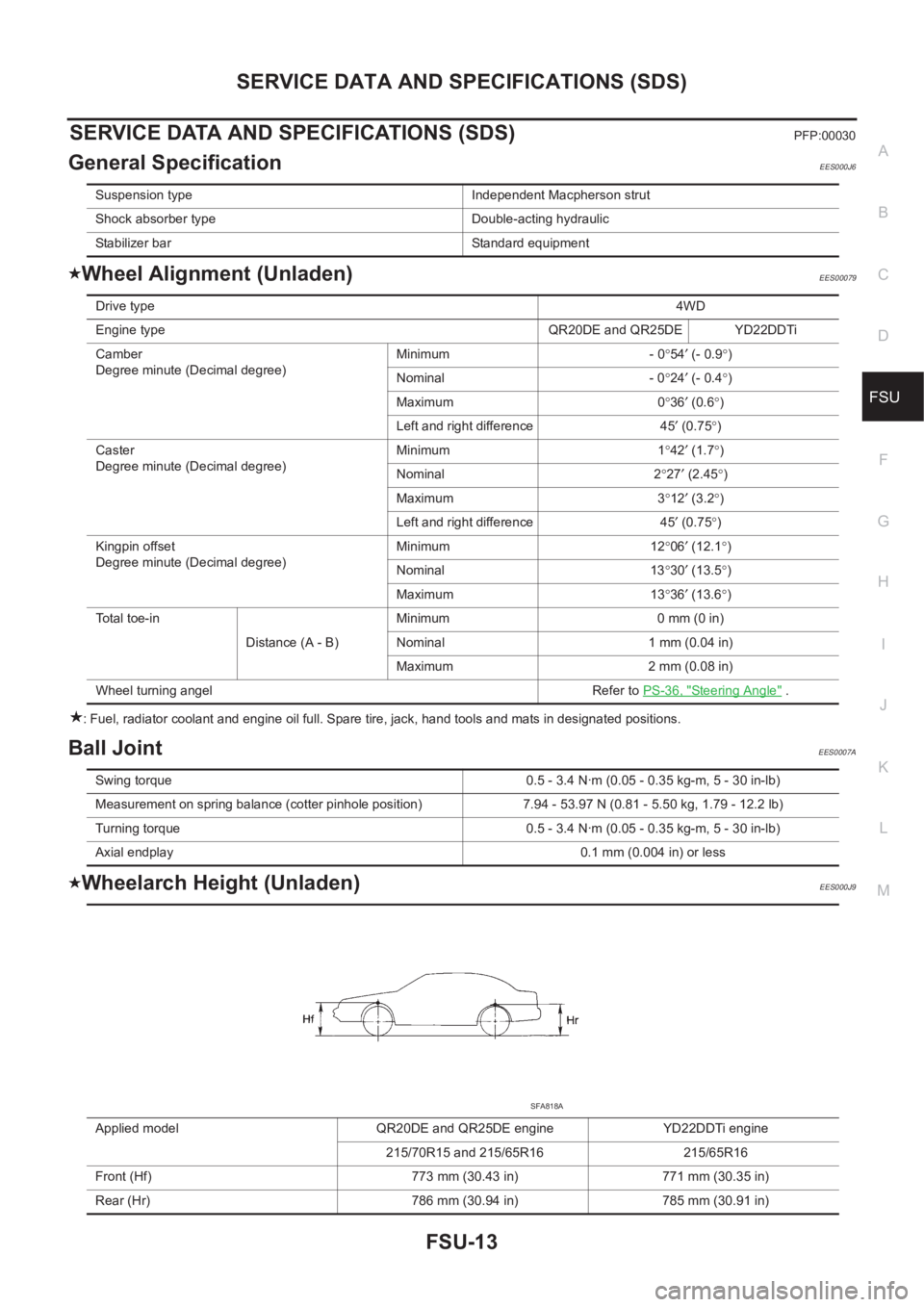
Wheelarch Height (Unladen)EES000J9
Suspension type Independent Macpherson strut
Shock absorber type Double-acting hydraulic
Stabilizer bar Standard equipment
Drive type4WD
Engine type QR20DE and QR25DE YD22DDTi
Camber
Degree minute (Decimal degree)Minimum - 0°54′ (- 0.9°)
Nominal - 0°24′ (- 0.4°)
Maximum 0°36′ (0.6°)
Left and right difference 45′ (0.75°)
Caster
Degree minute (Decimal degree)Minimum 1°42′ (1.7°)
Nominal 2°27′ (2.45°)
Maximum 3°12′ (3.2°)
Left and right difference 45′ (0.75°)
Kingpin offset
Degree minute (Decimal degree)Minimum 12°06′ (12.1°)
Nominal 13°30′ (13.5°)
Maximum 13°36′ (13.6°)
Total toe-in
Distance (A - B)Minimum 0 mm (0 in)
Nominal 1 mm (0.04 in)
Maximum 2 mm (0.08 in)
Wheel turning angel Refer to PS-36, "
Steering Angle" .
Swing torque 0.5 - 3.4 N·m (0.05 - 0.35 kg-m, 5 - 30 in-lb)
Measurement on spring balance (cotter pinhole position) 7.94 - 53.97 N (0.81 - 5.50 kg, 1.79 - 12.2 lb)
Turning torque 0.5 - 3.4 N·m (0.05 - 0.35 kg-m, 5 - 30 in-lb)
Axial endplay 0.1 mm (0.004 in) or less
Applied model QR20DE and QR25DE engine YD22DDTi engine
215/70R15 and 215/65R16 215/65R16
Front (Hf) 773 mm (30.43 in) 771 mm (30.35 in)
Rear (Hr) 786 mm (30.94 in) 785 mm (30.91 in)
SFA818A
Page 2785 of 3833

BRC-1
BRAKE CONTROL SYSTEM
F BRAKES
CONTENTS
C
D
E
G
H
I
J
K
L
M
SECTION
A
B
BRC
BRAKE CONTROL SYSTEM
4WD/ABS
PRECAUTIONS .......................................................... 4
Precautions for brake system ................................... 4
Precautions for brake control ................................... 4
PREPARATION ........................................................... 5
Special Service Tool ................................................. 5
Commercial Service Tool ......................................... 5
ALL MODE 4X4 SYSTEM .......................................... 6
System Description .................................................. 6
ABS FUNCTION ................................................... 6
4WD FUNCTION ................................................... 6
Control System Diagram .......................................... 6
TROUBLE DIAGNOSIS .............................................. 7
Fail-safe Function ..................................................... 7
How to Proceed with Trouble Diagnosis .................. 7
BASIC CONCEPT ................................................. 7
DIAGNOSIS FLOW ............................................... 8
ASKING COMPLAINTS ........................................ 9
TROUBLE DIAGNOSIS SHEET - EXAMPLE ....... 9
Component Parts Location ..................................... 10
Schematic ............................................................... 11
Wiring Diagram — ABS — ..................................... 12
Trouble Diagnosis Chart by Symptom .................... 18
4WD/ABS Control Unit Input/Output Signal Stan-
dard ........................................................................ 19
4WD/ABS CONTROL UNIT CONNECTOR TER-
MINAL ARRANGEMENT .................................... 19
REFERENCE STANDARD TABLE ..................... 19
CONSULT-II Functions ........................................... 23
CONSULT-II FUNCTION APPLICATION TABLE ... 23
SELF-DIAGNOSIS .............................................. 24
DATA MONITOR ................................................. 26
ACTIVE TEST ..................................................... 29
Component Inspection ........................................... 30
ABS ACTUATOR ................................................ 30
4WD SOLENOID VALVE .................................... 32
Basic Inspection ..................................................... 32
BASIC INSPECTION 1 BRAKE FLUID LEVEL
AND LEAKAGE INSPECTION ............................ 32
BASIC INSPECTION 2 INSPECTION FOR LOOSE POWER SUPPLY TERMINAL ............... 32
BASIC INSPECTION 3 ABS/4WD WARNING
LAMP INSPECTION ............................................ 32
Wheel Sensor System ............................................ 32
INSPECTION PROCEDURE .............................. 32
Control Unit Power Supply System ........................ 34
INSPECTION PROCEDURE .............................. 34
G -Sensor System (4WD models) .......................... 34
INSPECTION PROCEDURE .............................. 34
4WD Solenoid, Actuator Relay System .................. 35
4WD Mode Switch System ..................................... 37
Trouble Diagnoses for Symptoms .......................
... 38
4WD INDICATOR LAMP DOES NOT COME ON
FOR APPROXIMATELY 1 SECOND WHEN THE
IGNITION SWITCH IS TURNED TO ON ............. 38
4WD WARNING LAMP DOES NOT ILLUMINATE
WITH IGNITION ON ............................................ 39
4WD WARNING LAMP DOES NOT GO OUT
SEVERAL SECONDS AFTER ENGINE
STARTED.(4WD MODE INDICATOR LAMP
GOES OUT) ........................................................ 39
HEAVY TIGHT-CORNER BRAKING SYMPTOM
OCCURS WHEN THE VEHICLE IS DRIVEN IN
AUTO MODE AND THE STEERING WHEEL IS
TURNED FULLY TO EITHER SIDE AFTER THE
ENGINE IS STARTED ......................................... 39
4WD MODES CANNOT BE SWITCHED AFTER
ENGINE IS STARTED ......................................... 41
WHILE DRIVING, 4WD WARNING LAMP
FLASHES RAPIDLY. (WHEN IT FLASHERS FOR
APPROX. ONE MINUTE, THEN DOES NOT
ILLUMINATE.) ..................................................... 41
WHILE DRIVING, 4WD WARNING LAMP
FLASHES SLOWLY. (WHEN IT CONTINUES TO
ILLUMINATE UNTIL ENGINE TURNS OFF.) ...... 41
VEHICLE DOES NOT ENTER 4WD MODE
EVEN THOUGH 4WD WARNING LAMP IS OFF. ... 41
TIGHT-CORNER BRAKING SYMPTOM
OCCURS WHEN THE VEHICLE IS STARTED IN
AUTO WARNING LAMP REMAIN OFF). ............ 42
Page 2786 of 3833

BRC-2
4WD ACTUATOR RELAY (4WD SOLENOID
A C T U AT O R R E L AY ) T U R N S O N / O F F F R E -
QUENTLY ............................................................ 42
ABS Warning Lamp Does Not Illuminate. (ABS
Warning Lamp Does Not Come On When The Igni-
tion Switch Is Turned ON.) ...................................... 42
ABS Warning Lamp Illuminates With Ignition ON,
But Does Not Illuminates After A Few Seconds.
(ABS Warning Lamp Has Illuminated.) ................... 42
4WD Warning Lamp Does Not Illuminate With Igni-
tion ON. .................................................................. 43
4WD Warning Lamp Does Not Go Out Several Sec-
onds After Engine Is Started. (Drive Mode Indicator
Lamp Goes Out.) .................................................... 43
Heavy Tight-corner Braking Symptom Occurs
When The Vehicle Is Driven In Auto Mode And The
Steering Wheel Is Turned Fully To Either Side After
The Engine Is Started. ............................................ 44
Drive Modes Cannot Be Switched After Engine Is
Started. ................................................................... 45
Wheel Driving, 4WD Warning Lamp Flashes Rap-
idly. (When It Flashes For Approx. One Minute, Then
Does Not Illuminate.) .............................................. 45
Wheel Driving, 4WD Warning Lamp Flashes Slowly.
(When It Continues To Illuminate Until Engine Turns
OFF.) ....................................................................... 45
Vehicle Does Not Enter 4WD Mode Even Though
4WD Warning Lamp Is OFF. ................................... 46
Tight-corner Braking Symptom Occurs When The
Vehicle Is Started In Auto Mode (4WD Warning
Lamp Remain OFF). ............................................... 46
E-TS Actuator Relay (4WD Solenoid Actuator
Relay) Turns ON/OFF Frequently. .......................... 46
Inspection Of Drive Mode Change-over Switch Path ... 47
4WD/ABS CONTROL UNIT ...................................... 48
Removal and Installation ........................................ 48
REMOVAL ........................................................... 48
INSTALLATION .................................................... 48
WHEEL SENSORS ................................................... 49
Removal and Installation ........................................ 49
G-SENSOR (4WD MODEL ONLY) ............................ 50
Removal and Installation ........................................ 50
SENSOR ROTOR ................................................... ... 51
Removal and Installation ........................................ 51
REMOVAL ........................................................... 51
INSTALLATION .................................................... 51
ACTUATOR ............................................................... 52
Removal and Installation ........................................ 52
REMOVAL ........................................................... 53
INSTALLATION .................................................... 53
ESP/TCS/ABS
PRECAUTIONS ......................................................... 54
Precautions for Brake System ................................ 54
Precautions for Brake Control ................................ 54
Precautions for CAN System .................................. 54
FOR INSPECTION .............................................. 54
FOR HARNESS REPAIR .................................... 55PREPARATION ......................................................... 56
Special Service Tool ................................................ 56
Commercial Service Tool ........................................ 56
ON-VEHICLE SERVICE ............................................ 57
Adjustment of Neutral Position of Steering Wheel
Angle Sensor .......................................................... 57
GENERAL INFORMATION ....................................... 59
Fail-Safe .................................................................. 59
ABS SYSTEM ...................................................... 59
ESP/TCS SYSTEM .............................................. 59
Hydraulic Circuit ...................................................... 59
ABS Functions ........................................................ 59
TCS Functions ........................................................ 60
ESP Functions ........................................................ 60
System Diagram ..................................................... 61
CAN COMMUNICATION ........................................... 62
System Description ................................................. 62
FOR A/T MODELS ............................................... 62
FOR M/T MODELS .............................................. 62
TROUBLE DIAGNOSIS ............................................ 64
How to Perform Trouble Diagnoses for Quick and
Accurate Repair ...................................................... 64
INTRODUCTION ................................................. 64
WORK FLOW ...................................................... 65
ASKING COMPLAINTS ....................................... 66
EXAMPLE OF DIAGNOSIS SHEET .................... 66
Component Parts and Harness Connector Location ... 67
Schematic ............................................................... 68
Wiring Diagram —ESP/TCS/ABS— ..................... 69
Control Unit Input/Output Signal Standard .............. 75
STANDARDS USING A CIRCUIT TESTER AND
OSCILLOSCOPE ................................................. 75
STANDARDS WITH CONSULT-II ........................ 78
Functions of CONSULT-II ....................................... 80
CONSULT-II MAINLY FUNCTION APPLICA-
TION TO ESP/TCS/ABS ...................................... 80
SELF-DIAGNOSIS ............................................... 81
DATA MONITOR .................................................. 83
ACTIVE TEST ...................................................... 87
For Correct and Quick Diagnosis ............................ 90
PRECAUTIONS FOR TROUBLE DIAGNOSIS ... 90
Basic Inspection ...................................................... 91
PRELIMINARY CHECK 1: (BRAKE FLUID
LEVEL AND LEAK INSPECTION) ....................... 91
PRELIMINARY CHECK 2: (INSPECTION FOR
LOOSE POWER SUPPLY TERMINAL) ............... 92
PRELIMINARY CHECK 3: (INSPECTION FOR
ABS WARNING LAMP, ESP OFF INDICATOR
LAMP, AND SLIP INDICATOR LAMP) ................. 92
Inspection 1 Wheel Sensor and Circuit ................... 92
Inspection 2 Engine System ................................... 94
Inspection 3 ESP/TCS/ABS Control Unit System ... 94
Inspection 4 Pressure Sensor and the Circuit
between Pressure Sensor and ESP/TCS/ABS Con-
trol Unit. ................................................................... 95
Inspection 5 Steering wheel Angle Sensor and the
Circuit between Steering Wheel Angle Sensor and
ESP/TCS/ABS Control Unit. ................................... 96
Inspection 6 Yaw Rate Sensor and Side G sensor