torque NISSAN X-TRAIL 2001 Service Service Manual
[x] Cancel search | Manufacturer: NISSAN, Model Year: 2001, Model line: X-TRAIL, Model: NISSAN X-TRAIL 2001Pages: 3833, PDF Size: 39.49 MB
Page 294 of 3833

LU-14
[QR]
SERVICE DATA AND SPECIFICATIONS (SDS)
SERVICE DATA AND SPECIFICATIONS (SDS)
PFP:00030
Standard and LimitEBS00KO9
OIL PRESSURE
*:Engine oil temperature at 80°C (176°C)
OIL PUMP
Unit: mm (in)
REGULATOR VALVE
Unit: mm (in)
ENGINE OIL CAPACITY
Unit: (Imp qt)
Tightening TorqueEBS00KOA
Unit: N·m (kg-m, ft-lb)
Unit: N·m (kg-m, in-lb)* Engine speed (rpm)
Approximate discharge pressure kPa (bar, kg/cm
2 , psi)*
Idle speed
2,000
6,000 More than 98 (0.98, 1.0, 14)
294 (2.9, 3.0, 43)
392 (3.9, 4.0, 57)
Body to outer rotor radial clearance 0.114 - 0.179 (0.0045 - 0.0070)
Inner rotor to outer rotor tip clearance Below 0.220 (0.0087)
Body to inner rotor axial clearance 0.030 - 0.070 (0.0012 - 0.0028)
Body to outer rotor axial clearance 0.060 - 0.110 (0.0024 - 0.0043)
Inner rotor to brazed portion of housing clearance 0.035 - 0.070 (0.0014 - 0.0028)
Regulator valve to oil pump cover clearance 0.040 - 0.097 (0.0016 - 0.0038)
With oil filter change Approximately 3.9 (3-3/8)
Without oil filter change Approximately 3.5 (3-1/8)
Dry engine (engine overhaul) Approximately 4.5 (4)
Oil pressure switch 12.3 - 17.2 (1.25 - 1.75, 9 - 12)
Oil pan drain plug 29.4 - 39.2 (3.0 - 4.0, 22 - 28)
Oil filter14.7 - 20.5 (1.5 - 2.1, 11 - 15)
Oil pump assembly 6.4 - 7.5 (0.66 - 0.76, 57 - 66)*
Oil pump cover 5.9 - 7.9 (0.60 - 0.81, 52 - 70)*
Regulator plug 39.2 - 68.6 (4.0 - 6.9, 29 - 50)
Oil cooler34.3 - 44.1 (3.5 - 4.4, 26 - 32)
Oil cooler bracket 19.6 - 23.5 (2.0 - 2.3, 15 - 17)
Page 306 of 3833

LU-26
[YD22DDTi]
SERVICE DATA AND SPECIFICATIONS (SDS)
SERVICE DATA AND SPECIFICATIONS (SDS)
PFP:00030
Standard and LimitEBS00CTZ
OIL PRESSURE
OIL PUMP
Unit: mm (in)
REGULATOR VALVE
Unit: mm (in)
OIL CAPACITY
Unit: · (Imp qt)
Tightening TorqueEBS00B0F
Unit: N·m (kg-m, ft-lb)
Unit: N·m (kg-m, in-lb)* Engine speed rpm
Approximate discharge pressure kPa (bar, kg/cm
2 , psi)
Idle speed
2,000
4,000 More than 140 (1.40, 1.43, 20.3)
More than 270 (2.69, 2.75, 39.1)
More than 430 (4.29, 4.38, 62.3)
Body to outer rotor radial clearance 0.114 - 0.260 (0.0045 - 0.0102)
Inner rotor to outer rotor tip clearance Below 0.18 (0.0071)
Body to inner rotor axial clearance 0.050 - 0.090 (0.0020 - 0.0035)
Body to outer rotor axial clearance 0.030 - 0.190 (0.0012 - 0.0075)
Inner rotor to brazed portion of housing clearance 0.045 - 0.091 (0.0018 - 0.0036)
Regulator valve to oil pump cover clearance 0.040 - 0.097 (0.0016 - 0.0038)
With oil filter change Approximately 5.2 (4-5/8 Imp qt)
Without oil filter change Approximately 4.9 (4-3/8 Imp qt)
Dry engine (engine overhaul) Approximately 6.3 (5-1/2 Imp qt)
Oil pressure switch 13 - 17 (1.4 - 1.7, 10 - 12)
Oil pan drain plug 29 - 39 (3.0 - 4.0, 22 - 29)
Oil filter bracket20 -23 (2.0 - 2.4, 15 - 17)
Oil filter body20 - 24 (2.0 - 2.5, 15 - 18)
Oil pump assembly 6.4 - 7.4 (0.65 - 0.76, 57 - 65)*
Oil pump cover 5.9 - 7.8 (0.6 - 0.8, 52 - 69)*
Regulator plug40 - 68 (4.0 - 7.0, 29 - 50)
Water hose connector for oil cooler 25 - 31 (2.5 - 3.2, 18 - 23)
Connecting bolt20 - 29 (2.1 - 2.9, 15 - 21)
Page 307 of 3833
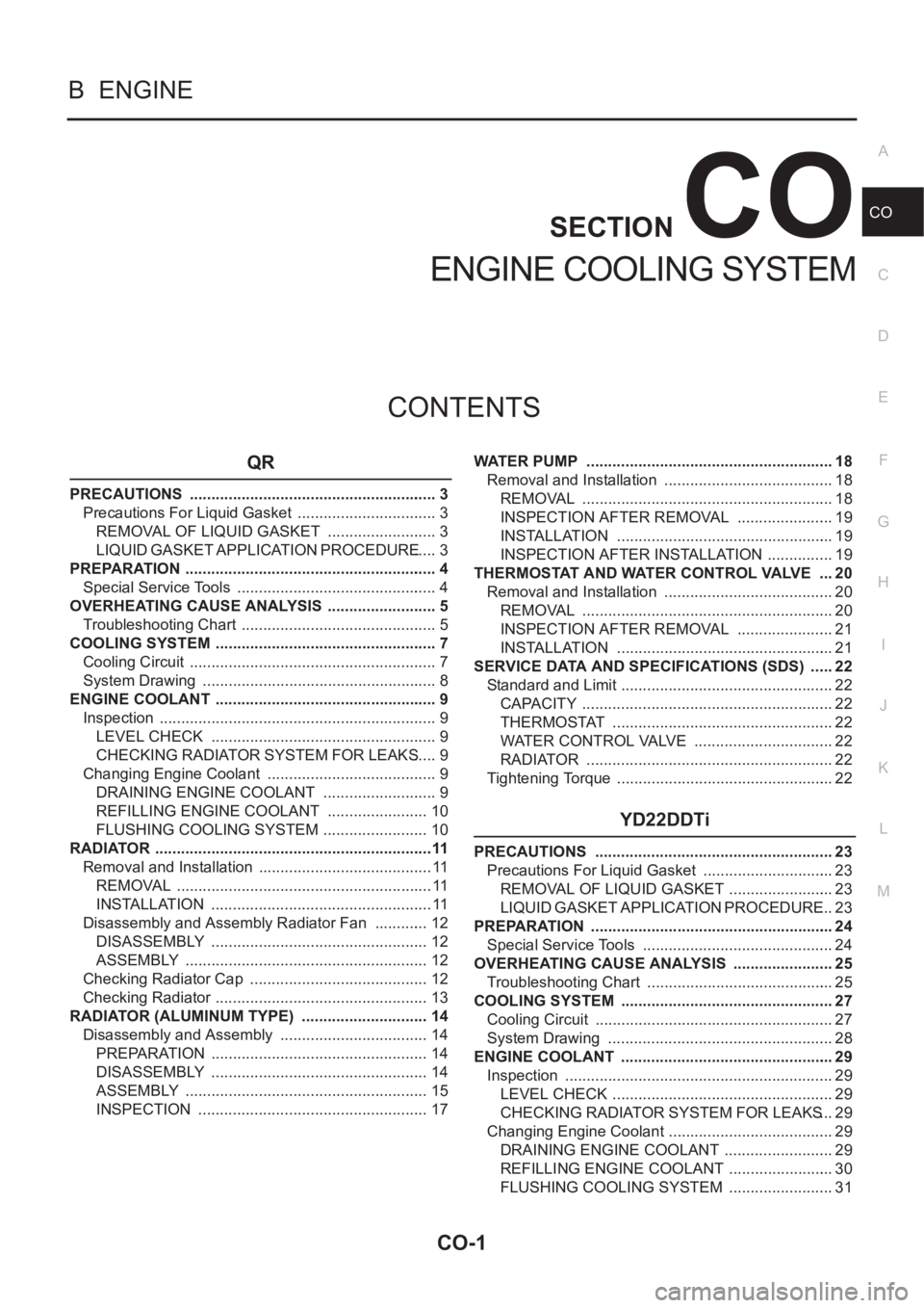
CO-1
ENGINE COOLING SYSTEM
B ENGINE
CONTENTS
C
D
E
F
G
H
I
J
K
L
M
SECTION
A
CO
ENGINE COOLING SYSTEM
QR
PRECAUTIONS .......................................................... 3
Precautions For Liquid Gasket ................................. 3
REMOVAL OF LIQUID GASKET .......................... 3
LIQUID GASKET APPLICATION PROCEDURE ..... 3
PREPARATION ........................................................... 4
Special Service Tools ............................................... 4
OVERHEATING CAUSE ANALYSIS .......................... 5
Troubleshooting Chart .............................................. 5
COOLING SYSTEM .................................................... 7
Cooling Circuit .......................................................... 7
System Drawing ....................................................... 8
ENGINE COOLANT .................................................... 9
Inspection ................................................................. 9
LEVEL CHECK ..................................................... 9
CHECKING RADIATOR SYSTEM FOR LEAKS ..... 9
Changing Engine Coolant ........................................ 9
DRAINING ENGINE COOLANT ........................... 9
REFILLING ENGINE COOLANT ........................ 10
FLUSHING COOLING SYSTEM ......................... 10
RADIATOR .................................................................11
Removal and Installation ......................................... 11
REMOVAL ............................................................ 11
INSTALLATION .................................................... 11
Disassembly and Assembly Radiator Fan ............. 12
DISASSEMBLY ................................................... 12
ASSEMBLY ......................................................... 12
Checking Radiator Cap .......................................... 12
Checking Radiator .................................................. 13
RADIATOR (ALUMINUM TYPE) .............................. 14
Disassembly and Assembly ................................... 14
PREPARATION ................................................... 14
DISASSEMBLY ................................................... 14
ASSEMBLY ......................................................... 15
INSPECTION ...................................................... 17WATER PUMP .......................................................... 18
Removal and Installation ........................................ 18
REMOVAL ........................................................... 18
INSPECTION AFTER REMOVAL ....................... 19
INSTALLATION ................................................... 19
INSPECTION AFTER INSTALLATION ................ 19
THERMOSTAT AND WATER CONTROL VALVE .... 20
Removal and Installation ........................................ 20
REMOVAL ........................................................... 20
INSPECTION AFTER REMOVAL ....................... 21
INSTALLATION ................................................
... 21
SERVICE DATA AND SPECIFICATIONS (SDS) ...... 22
Standard and Limit .................................................. 22
CAPACITY ........................................................... 22
THERMOSTAT .................................................... 22
WATER CONTROL VALVE ................................. 22
RADIATOR ....................................................... ... 22
Tightening Torque ................................................... 22
YD22DDTi
PRECAUTIONS ........................................................ 23
Precautions For Liquid Gasket ............................... 23
REMOVAL OF LIQUID GASKET ......................... 23
LIQUID GASKET APPLICATION PROCEDURE ... 23
PREPARATION ......................................................... 24
Special Service Tools ............................................. 24
OVERHEATING CAUSE ANALYSIS ........................ 25
Troubleshooting Chart ............................................ 25
COOLING SYSTEM .................................................. 27
Cooling Circuit ........................................................ 27
System Drawing ..................................................... 28
ENGINE COOLANT .................................................. 29
Inspection ............................................................... 29
LEVEL CHECK .................................................... 29
CHECKING RADIATOR SYSTEM FOR LEAKS ... 29
Changing Engine Coolant ....................................... 29
DRAINING ENGINE COOLANT .......................... 29
REFILLING ENGINE COOLANT ......................... 30
FLUSHING COOLING SYSTEM ......................... 31
Page 308 of 3833

CO-2
RADIATOR ................................................................ 32
Removal and Installation ........................................ 32
REMOVAL ........................................................... 32
INSTALLATION .................................................... 32
Disassembly and Assembly Radiator Fan .............. 33
DISASSEMBLY ................................................... 33
ASSEMBLY ......................................................... 33
Checking Radiator Cap .......................................... 33
Checking Radiator .................................................. 34
RADIATOR (ALUMINUM TYPE) ............................... 35
Disassembly and Assembly .................................... 35
PREPARATION ................................................... 35
DISASSEMBLY ................................................... 35
ASSEMBLY ......................................................... 36
INSPECTION ....................................................... 38WATER PUMP ........................................................... 39
Removal and Installation ......................................... 39
REMOVAL ............................................................ 39
INSPECTION AFTER REMOVAL ........................ 39
INSTALLATION .................................................... 40
INSPECTION AFTER INSTALLATION ................ 40
THERMOSTAT AND WATER PIPING ....................... 41
Removal and Installation ......................................... 41
REMOVAL ............................................................ 41
INSPECTION AFTER REMOVAL ........................ 42
INSTALLATION .................................................... 42
SERVICE DATA AND SPECIFICATIONS (SDS) ...... 43
Standard and Limit .................................................. 43
CAPACITY ........................................................... 43
THERMOSTAT ..................................................... 43
RADIATOR ........................................................... 43
Tightening Torque ................................................... 43
Page 328 of 3833

CO-22
[QR]
SERVICE DATA AND SPECIFICATIONS (SDS)
SERVICE DATA AND SPECIFICATIONS (SDS)
PFP:00030
Standard and LimitEBS00KOP
CAPACITY
Unit: (lmp qt)
THERMOSTAT
WATER CONTROL VALVE
RADIATOR
Unit: kPa (bar, kg/cm2 , psi)
Tightening TorqueEBS00KOQ
Unit: N·m (kg-m, ft-lb)
Unit: N·m (kg-m, in-lb)*
Engine coolant capacity [With reservoir tank (MAX level)] Approximately 7.1 (6-1/4)
Reservoir tank0.6 (1/2)
Valve opening temperature 80.5 - 83.5°C (177 - 182°F)
Valve liftMore than 8 mm/ 95°C (0.315 in/203°F)
Valve closing temperature 77°C (171°F)
Valve opening temperature 93.5 - 96.5°C (200 - 206°F)
Valve liftMore than 8 mm/108°C (0.315 in/226°F)
Valve closing temperature 90°C (194° F)
Cap relief pressureStandard 78 - 98 (0.78 - 0.98, 0.8 - 1.0, 11- 14)
Limit 59 (0.59, 0.6, 9)
Leakage test pressure 157 (1.57, 1.6, 23)
Cylinder block drain plug 7.8 - 11.8 (0.8 - 1.2, 69 - 104)*
Radiator mounting bracket 3.8 - 4.5 (0.39 - 0.46, 34 - 39)*
Radiator fan assembly 3.8 - 4.5 (0.39 - 0.46, 34 - 39)*
Radiator fan2.9 - 3.9 (0.30 - 0.40, 26 - 34)*
Radiator fan motor 3.9 - 4.9 (0.40 - 0.50, 35 - 43)*
Water pump20.8 - 28.2 (2.1 - 2.9, 16 - 20)
Water pump housing 20.8 - 28.2 (2.1 - 2.9, 16 - 20)
Water inlet20.8 - 28.2 (2.1 - 2.9, 16 - 20)
Water outlet20.8 - 28.2 (2.1 - 2.9, 16 - 20)
Water pipe20.8 - 28.2 (2.1 - 2.9, 16 - 20)
Hater pipe20.8 - 28.2 (2.1 - 2.9, 16 - 20)
Engine coolant temperature sensor 19.6 - 29.4 (2.0 - 3.0, 15 - 21)
Page 349 of 3833

SERVICE DATA AND SPECIFICATIONS (SDS)
CO-43
[YD22DDTi]
C
D
E
F
G
H
I
J
K
L
MA
CO
SERVICE DATA AND SPECIFICATIONS (SDS)PFP:00030
Standard and LimitEBS00CU0
CAPACITY
Unit: (lmp qt)
THERMOSTAT
RADIATOR
Unit: kPa (bar, kg/cm2 , psi)
Tightening TorqueEBS00BKE
Unit: N·m (kg-m, ft-lb)
Unit: N·m (kg-m, in-lb)*
Engine coolant capacity [With reservoir tank (MAX level)] 9.5 (8-3/8)
Reservoir tank0.6 (1/2)
Valve opening temperature 80 - 84°C (176 - 183°F)
Va l v e l i f tMore than 10 mm/ 95°C (0.39 in/203°F)
Valve closing temperature Approximately 77°C (171°F)
Cap relief pressureStandard 78 - 98 (0.78 - 0.98, 0.8 - 1.0, 11 - 14)
Limit 59 (0.59, 0.6, 9)
Leakage test pressure 157 (1.57, 1.6, 23)
Cylinder block drain plug 7.8 - 11.8 (0.8 - 1.2, 69 - 104)*
Air relief plug6.7 - 7.9 (0.68 - 0.81, 59 - 70)*
Radiator mounting bracket
Radiator fan assembly
Radiator fan
Radiator fan motor3.8 - 4.5 (0.39 - 0.45, 34 - 39)*
3.8 - 4.5 (0.39 - 0.45, 34 - 39)*
2.9 - 3.9 (0.30 - 0.40, 26 - 34)*
3.9 - 4.9 (0.40 - 0.50, 35 - 43)*
Water pump
Water pump pulley
Water inlet
Thermostat housing
Water inlet pipe
Hater return pipe23.0 - 30.0 (2.3 - 3.1, 17 - 22)
7.3 - 9.6 (0.74 - 0.98, 65 - 85)*
21.0 - 28.0 (2.1 - 2.9, 16 - 20)
21.0 - 28.0 (2.1 - 2.9, 16 - 20)
21.0 - 28.0 (2.1 - 2.9, 16 - 20)
21.0 - 28.0 (2.1 - 2.9, 16 - 20)
Page 377 of 3833

PRECAUTIONS
EC-27
[QR25(WITH EURO-OBD)]
C
D
E
F
G
H
I
J
K
L
MA
EC
●After performing each TROUBLE DIAGNOSIS, perform
“DTC Confirmation Procedure” or “Overall Function
Check”.
The DTC should not be displayed in the “DTC Confirmation
Procedure” if the repair is completed. The “Overall Func-
tion Check” should be a good result if the repair is com-
pleted.
●When measuring ECM signals with a circuit tester, never
allow the two tester probes to contact.
Accidental contact of probes will cause a short circuit and
damage the ECM power transistor.
●Do not use ECM ground terminals when measuring input/
output voltage. Doing so may result in damage to the ECM's
transistor. Use a ground other than ECM terminals, such as
the ground.
●Do not operate fuel pump when there is no fuel in lines.
●Tighten fuel hose clamps to the specified torque.
SAT652J
SEF348N
PBIB0513E
Page 393 of 3833

BASIC SERVICE PROCEDURE
EC-43
[QR25(WITH EURO-OBD)]
C
D
E
F
G
H
I
J
K
L
MA
EC
4. Install the fuel pressure gauge as shown in the figure.
●Wipe off oil or dirt from hose insertion part using cloth moist-
ened with gasoline.
●Apply proper amount of gasoline between top of the fuel tube
and No.1 spool.
●Insert fuel hose for fuel pressure check until it touches the
No.1 spool on fuel tube.
●Use NISSAN genuine hose clamp (part number: 16439
N4710 or 16439 40U00).
●When reconnecting fuel line, always use new clamps.
●When reconnecting fuel hose, check the original fuel hose for
damage and abnormality.
●Use a torque driver to tighten clamps.
●Install hose clamp to the position within 1 - 2 mm (0.04 - 0.08
in).
●Make sure that clamp screw does not contact adjacent parts.
5. After connecting fuel hose for fuel pressure check, pull the hose
with a force of approximately 98 N (10 kg, 22 lb) to confirm fuel
tube does not come off.
6. Turn ignition switch “ON”, and check for fuel leakage.
7. Start engine and check for fuel leakage.
8. Read the indication of fuel pressure gauge.
●Do not perform fuel pressure check with system operating. Fuel pressure gauge may indicate false
readings.
●During fuel pressure check, confirm for fuel leakage from fuel connection every 3 minutes.
9. If result is unsatisfactory, go to next step.
10. Check the following.
●Fuel hoses and fuel tubes for clogging
●Fuel filter for clogging
●Fuel pump
●Fuel pressure regulator for clogging
If OK, replace fuel pressure regulator.
If NG, repair or replace.Tightening torque: 1 - 1.5 N·m (0.1 - 0.15 kg-m,
9 - 13 in-lb)
At idling:
Approximately 350 kPa (3.5 bar, 3.57 kg/cm
2 , 51 psi)
PBIB0669E
PBIB0670E
Page 475 of 3833

DTC P0011 IVT CONTROL
EC-125
[QR25(WITH EURO-OBD)]
C
D
E
F
G
H
I
J
K
L
MA
EC
DTC P0011 IVT CONTROLPFP:23796
DescriptionEBS00M1K
SYSTEM DESCRIPTION
This mechanism hydraulically controls cam phases continuously with the fixed operating angle of the intake
valve.
The ECM receives signals such as crankshaft position, camshaft position, engine speed, and engine coolant
temperature. Then, the ECM sends ON/OFF pulse duty signals to the intake valve timing control solenoid
valve depending on driving status. This makes it possible to control the shut/open timing of the intake valve to
increase engine torque in low/mid speed range and output in high-speed range.
CONSULT-II Reference Value in Data Monitor ModeEBS00M1L
Specification data are reference values.
ECM Terminals and Reference ValueEBS00M1M
Specification data are reference values and are measured between each terminal and ground.
Pulse signal is measured by CONSULT-II
CAUTION:
Do not use ECM ground terminals when measuring input/output voltage. Doing so may result in dam-
age to the ECM's transistor. Use a ground other than ECM terminals, such as the ground.
Sensor Input signal to ECM function ECM Actuator
Crankshaft position sensor (POS) Engine speed
Intake valve
timing controlIntake valve timing control
solenoid valve Camshaft position sensor (PHASE) Engine speed and piston position
Engine coolant temperature sensor Engine coolant temperature
Wheel sensor Vehicle speed
PBIB0540E
MONITOR ITEM CONDITION SPECIFICATION
INT/V TIM (B1)
●Engine: After warming up
●Shift lever: N
●Air conditioner switch: OFF
●No-loadIdle−5° - 5°CA
When revving engine up to 2,000 rpm
quicklyApprox. 0° - 20°CA
INT/V SOL (B1)
●Engine: After warming up
●Shift lever: N
●Air conditioner switch: OFF
●No-loadIdle 0% - 2%
When revving engine up to 2,000 rpm
quicklyApprox. 0% - 50%
Page 516 of 3833

EC-166
[QR25(WITH EURO-OBD)]
DTC P0132 HO2S1
Diagnostic Procedure
EBS00M3F
1. RETIGHTEN HEATED OXYGEN SENSOR 1
1. Turn ignition switch “OFF”.
2. Loosen and retighten heated oxygen sensor 1.
>> GO TO 2.
2. CHECK HO2S1 GROUND CIRCUIT FOR OPEN AND SHORT
1. Disconnect heated oxygen sensor 1 harness connector.
2. Check harness continuity between HO2S1 terminal 3 and
engine ground.
Refer to Wiring Diagram.
3. Also check harness for short to ground and short to power.
OK or NG
OK >> GO TO 3.
NG >> Repair open circuit or short to power in harness or con-
nectors.
3. CHECK HO2S1 INPUT SIGNAL CIRCUIT FOR OPEN AND SHORT
1. Disconnect heated oxygen sensor 1 harness connector.
2. Disconnect ECM harness connector.
3. Check harness continuity between ECM terminal 92 and HO2S1
terminal 2.
Refer to Wiring Diagram.
4. Check harness continuity between ECM terminal 92 or HO2S1
terminal 2 and ground.
Refer to Wiring Diagram.
5. Also check harness for short to power.
OK or NG
OK >> GO TO 4.
NG >> Repair open circuit or short to ground or short to power in harness or connectors. Tightening torque: 40 - 50 N·m (4.1 - 5.1 kg-m, 30 - 37 ft-lb)
PBIB0499E
Continuity should exist.
PBIB0500E
Continuity should exist.
Continuity should not exist.
PBIB0500E