wheel NISSAN X-TRAIL 2001 Service Service Manual
[x] Cancel search | Manufacturer: NISSAN, Model Year: 2001, Model line: X-TRAIL, Model: NISSAN X-TRAIL 2001Pages: 3833, PDF Size: 39.49 MB
Page 423 of 3833
TROUBLE DIAGNOSIS
EC-73
[QR25(WITH EURO-OBD)]
C
D
E
F
G
H
I
J
K
L
MA
EC
Basic InspectionEBS00M0V
1.INSPECTION START
1. Check service records for any recent repairs that may indicate a related incident, or a current need for
scheduled maintenance.
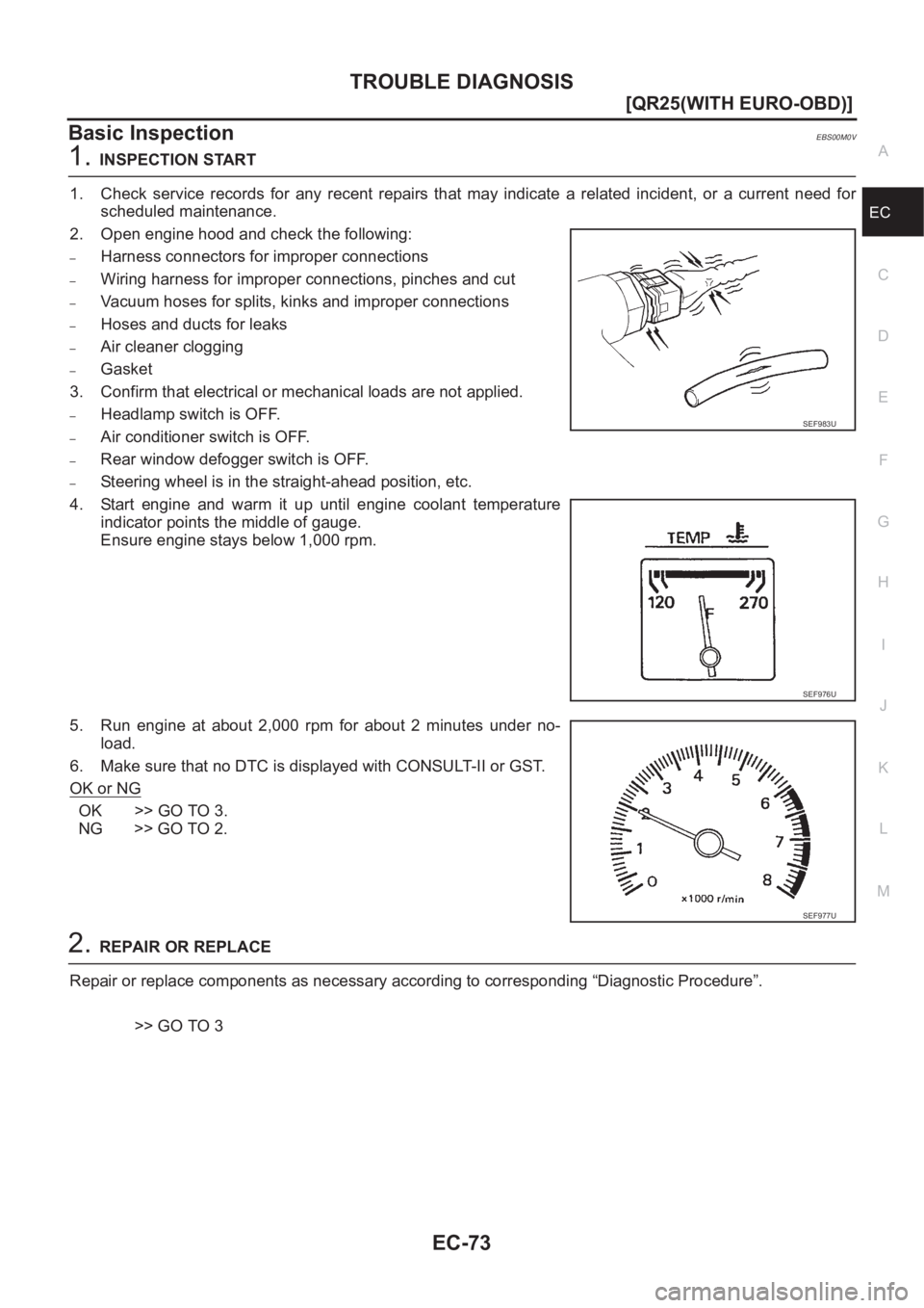
2. Open engine hood and check the following:
–Harness connectors for improper connections
–Wiring harness for improper connections, pinches and cut
–Vacuum hoses for splits, kinks and improper connections
–Hoses and ducts for leaks
–Air cleaner clogging
–Gasket
3. Confirm that electrical or mechanical loads are not applied.
–Headlamp switch is OFF.
–Air conditioner switch is OFF.
–Rear window defogger switch is OFF.
–Steering wheel is in the straight-ahead position, etc.
4. Start engine and warm it up until engine coolant temperature
indicator points the middle of gauge.
Ensure engine stays below 1,000 rpm.
5. Run engine at about 2,000 rpm for about 2 minutes under no-
load.
6. Make sure that no DTC is displayed with CONSULT-II or GST.
OK or NG
OK >> GO TO 3.
NG >> GO TO 2.
2.REPAIR OR REPLACE
Repair or replace components as necessary according to corresponding “Diagnostic Procedure”.
>> GO TO 3
SEF983U
SEF976U
SEF977U
Page 441 of 3833
TROUBLE DIAGNOSIS
EC-91
[QR25(WITH EURO-OBD)]
C
D
E
F
G
H
I
J
K
L
MA
EC
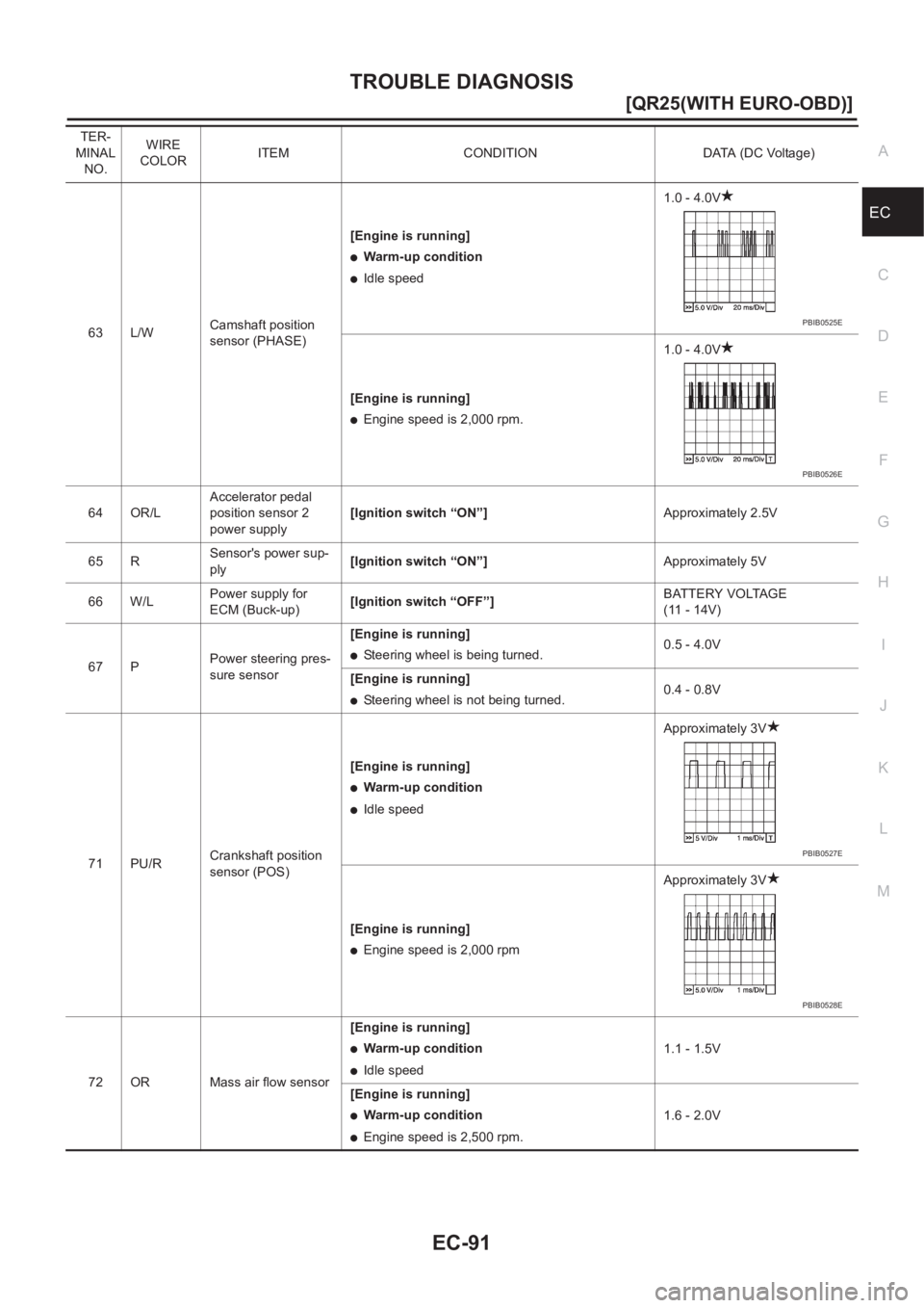
63 L/WCamshaft position
sensor (PHASE)[Engine is running]
●Warm-up condition
●Idle speed1.0 - 4.0V
[Engine is running]
●Engine speed is 2,000 rpm.1.0 - 4.0V
64 OR/LAccelerator pedal
position sensor 2
power supply[Ignition switch “ON”]Approximately 2.5V
65 RSensor's power sup-
ply[Ignition switch “ON”]Approximately 5V
66 W/LPower supply for
ECM (Buck-up)[Ignition switch “OFF”]BATTERY VOLTAGE
(11 - 14V)
67 PPower steering pres-
sure sensor[Engine is running]
●Steering wheel is being turned.0.5 - 4.0V
[Engine is running]
●Steering wheel is not being turned.0.4 - 0.8V
71 PU/RCrankshaft position
sensor (POS)[Engine is running]
●Warm-up condition
●Idle speedApproximately 3V
[Engine is running]
●Engine speed is 2,000 rpmApproximately 3V
72 OR Mass air flow sensor[Engine is running]
●Warm-up condition
●Idle speed1.1 - 1.5V
[Engine is running]
●Warm-up condition
●Engine speed is 2,500 rpm.1.6 - 2.0V TER-
MINAL
NO.WIRE
COLORITEM CONDITION DATA (DC Voltage)
PBIB0525E
PBIB0526E
PBIB0527E
PBIB0528E
Page 445 of 3833
TROUBLE DIAGNOSIS
EC-95
[QR25(WITH EURO-OBD)]
C
D
E
F
G
H
I
J
K
L
MA
EC*1 The following emission-related diagnostic information is cleared when the ECM memory is erased.
1. Diagnostic trouble codes
2. 1st trip diagnostic trouble codes
3. Freeze frame data
4. 1st trip freeze frame data
5. System readiness test (SRT) codes
6. Test values
7. Others
ENGINE CONTROL COMPONENT PARTS/CONTROL SYSTEMS APPLICATION
Function test This mode is used to inform customers when their vehicle condition requires periodic maintenance.
ECM part number ECM part number can be read.Diagnostic test mode Function
ItemDIAGNOSTIC TEST MODE
WORK
SUP-
PORTSELF-DIAGNOSTIC
RESULTS
DATA
MONI-
TORDATA
MONI-
TOR
(SPEC)ACTIVE
TESTDTC & SRT
CONFIRMATION
DTC*1FREEZE
FRAME
DATA*2SRT
STATUSDTC
WORK
SUP-
PORT
ENGINE CONTROL COMPONENT PARTS
INPUT
Crankshaft position sensor (POS)××××
Camshaft position sensor (PHASE)×
Mass air flow sensor×××
Engine coolant temperature sensor×××××
Heated oxygen sensor 1×××××
Heated oxygen sensor 2×××××
Wheel sensor××××
Accelerator pedal position sensor×××
Throttle position sensor×××
Intake air temperature sensor×××
Knock sensor×
Refrigerant pressure sensor××
Ignition switch (start signal)××
Closed throttle position switch
(accelerator pedal position sensor
signal)××
Air conditioner switch××
Park/neutral position (PNP) switch×××
Stop lamp switch×××
Power steering pressure sensor×××
Battery voltage××
Load signal××
Page 456 of 3833
EC-106
[QR25(WITH EURO-OBD)]
TROUBLE DIAGNOSIS
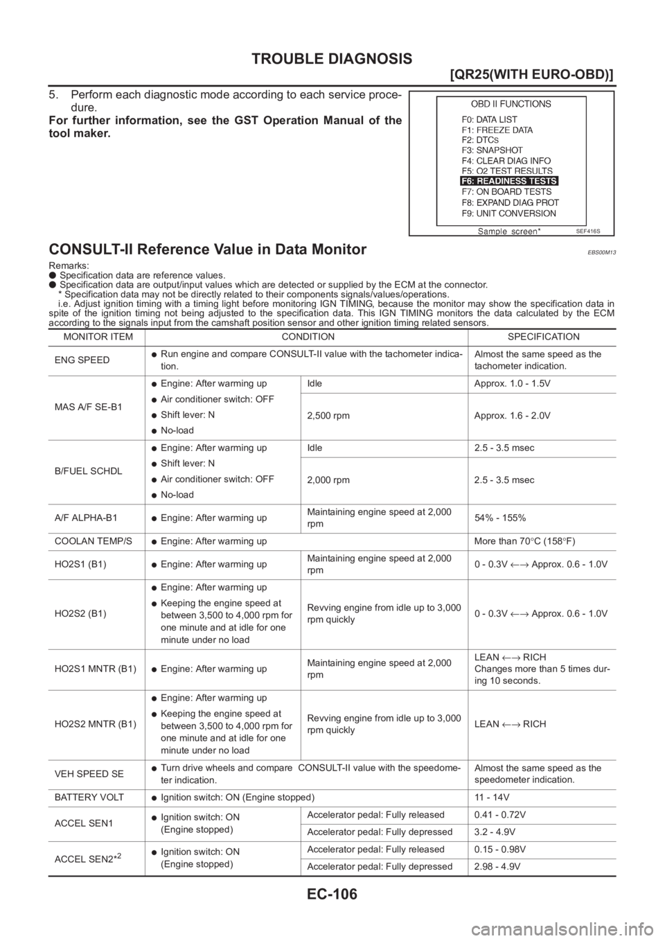
5. Perform each diagnostic mode according to each service proce-
dure.
For further information, see the GST Operation Manual of the
tool maker.
CONSULT-II Reference Value in Data MonitorEBS00M13
Remarks:
● Specification data are reference values.
● Specification data are output/input values which are detected or supplied by the ECM at the connector.
* Specification data may not be directly related to their components signals/values/operations.
i.e. Adjust ignition timing with a timing light before monitoring IGN TIMING, because the monitor may show the specification data in
spite of the ignition timing not being adjusted to the specification data. This IGN TIMING monitors the data calculated by the ECM
according to the signals input from the camshaft position sensor and other ignition timing related sensors.
SEF416S
MONITOR ITEM CONDITION SPECIFICATION
ENG SPEED
●Run engine and compare CONSULT-II value with the tachometer indica-
tion.Almost the same speed as the
tachometer indication.
MAS A/F SE-B1
●Engine: After warming up
●Air conditioner switch: OFF
●Shift lever: N
●No-loadIdle Approx. 1.0 - 1.5V
2,500 rpm Approx. 1.6 - 2.0V
B/FUEL SCHDL
●Engine: After warming up
●Shift lever: N
●Air conditioner switch: OFF
●No-loadIdle 2.5 - 3.5 msec
2,000 rpm 2.5 - 3.5 msec
A/F ALPHA-B1
●Engine: After warming upMaintaining engine speed at 2,000
rpm54% - 155%
COOLAN TEMP/S
●Engine: After warming up More than 70°C (158°F)
HO2S1 (B1)
●Engine: After warming upMaintaining engine speed at 2,000
rpm0 - 0.3V ←→ Approx. 0.6 - 1.0V
HO2S2 (B1)
●Engine: After warming up
●Keeping the engine speed at
between 3,500 to 4,000 rpm for
one minute and at idle for one
minute under no loadRevving engine from idle up to 3,000
rpm quickly0 - 0.3V ←→ Approx. 0.6 - 1.0V
HO2S1 MNTR (B1)
●Engine: After warming upMaintaining engine speed at 2,000
rpmLEAN ←→ RICH
Changes more than 5 times dur-
ing 10 seconds.
HO2S2 MNTR (B1)
●Engine: After warming up
●Keeping the engine speed at
between 3,500 to 4,000 rpm for
one minute and at idle for one
minute under no loadRevving engine from idle up to 3,000
rpm quicklyLEAN ←→ RICH
VEH SPEED SE
●Turn drive wheels and compare CONSULT-II value with the speedome-
ter indication.Almost the same speed as the
speedometer indication.
BATTERY VOLT
●Ignition switch: ON (Engine stopped) 11 - 14V
ACCEL SEN1
●Ignition switch: ON
(Engine stopped)Accelerator pedal: Fully released 0.41 - 0.72V
Accelerator pedal: Fully depressed 3.2 - 4.9V
ACCEL SEN2*
2●Ignition switch: ON
(Engine stopped)Accelerator pedal: Fully released 0.15 - 0.98V
Accelerator pedal: Fully depressed 2.98 - 4.9V
Page 457 of 3833
TROUBLE DIAGNOSIS
EC-107
[QR25(WITH EURO-OBD)]
C
D
E
F
G
H
I
J
K
L
MA
EC
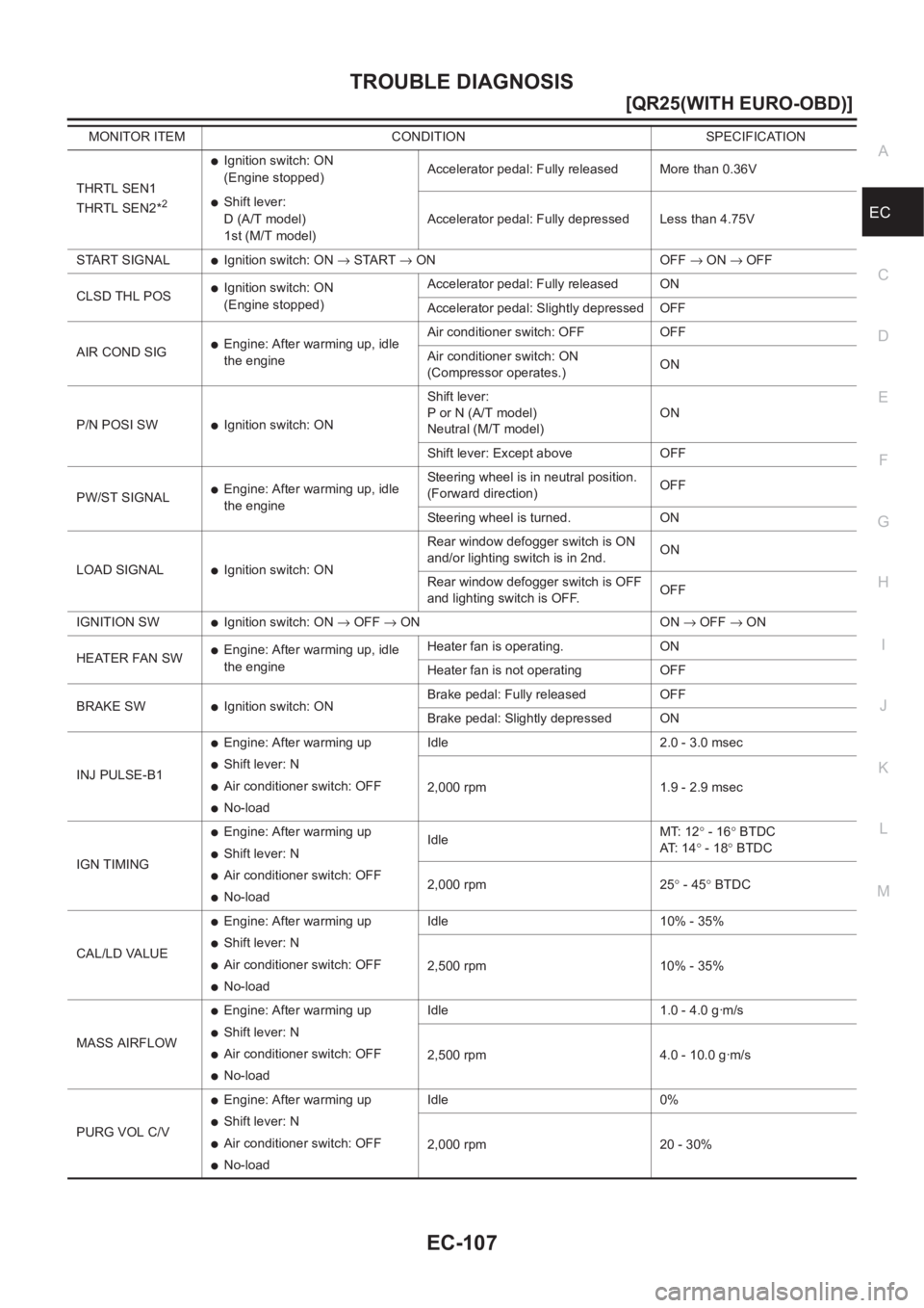
THRTL SEN1
THRTL SEN2*2
●Ignition switch: ON
(Engine stopped)Accelerator pedal: Fully released More than 0.36V
●Shift lever:
D (A/T model)
1st (M/T model)Accelerator pedal: Fully depressed Less than 4.75V
START SIGNAL
●Ignition switch: ON → START → ON OFF → ON → OFF
CLSD THL POS
●Ignition switch: ON
(Engine stopped)Accelerator pedal: Fully released ON
Accelerator pedal: Slightly depressed OFF
AIR COND SIG
●Engine: After warming up, idle
the engineAir conditioner switch: OFF OFF
Air conditioner switch: ON
(Compressor operates.)ON
P/N POSI SW
●Ignition switch: ONShift lever:
P or N (A/T model)
Neutral (M/T model)ON
Shift lever: Except above OFF
PW/ST SIGNAL
●Engine: After warming up, idle
the engineSteering wheel is in neutral position.
(Forward direction)OFF
Steering wheel is turned. ON
LOAD SIGNAL
●Ignition switch: ONRear window defogger switch is ON
and/or lighting switch is in 2nd.ON
Rear window defogger switch is OFF
and lighting switch is OFF.OFF
IGNITION SW
●Ignition switch: ON → OFF → ON ON → OFF → ON
HEATER FAN SW
●Engine: After warming up, idle
the engineHeater fan is operating. ON
Heater fan is not operating OFF
BRAKE SW
●Ignition switch: ONBrake pedal: Fully released OFF
Brake pedal: Slightly depressed ON
INJ PULSE-B1
●Engine: After warming up
●Shift lever: N
●Air conditioner switch: OFF
●No-loadIdle 2.0 - 3.0 msec
2,000 rpm 1.9 - 2.9 msec
IGN TIMING
●Engine: After warming up
●Shift lever: N
●Air conditioner switch: OFF
●No-loadIdleMT: 12° - 16° BTDC
AT: 1 4° - 18° BTDC
2,000 rpm 25° - 45° BTDC
CAL/LD VALUE
●Engine: After warming up
●Shift lever: N
●Air conditioner switch: OFF
●No-loadIdle 10% - 35%
2,500 rpm 10% - 35%
MASS AIRFLOW
●Engine: After warming up
●Shift lever: N
●Air conditioner switch: OFF
●No-loadIdle 1.0 - 4.0 g·m/s
2,500 rpm 4.0 - 10.0 g·m/s
PURG VOL C/V
●Engine: After warming up
●Shift lever: N
●Air conditioner switch: OFF
●No-loadIdle 0%
2,000 rpm 20 - 30% MONITOR ITEM CONDITION SPECIFICATION
Page 461 of 3833
TROUBLE DIAGNOSIS - SPECIFICATION VALUE
EC-111
[QR25(WITH EURO-OBD)]
C
D
E
F
G
H
I
J
K
L
MA
EC
TROUBLE DIAGNOSIS - SPECIFICATION VALUEPFP:00031
DescriptionEBS00M15
The specification (SP) value indicates the tolerance of the value that is displayed in “DATA MONITOR (SPEC)”
mode of CONSULT-II during normal operation of the Engine Control System. When the value in “DATA MONI-
TOR (SPEC)” mode is within the SP value, the Engine Control System is confirmed OK. When the value in
“DATA MONITOR (SPEC)” mode is NOT within the SP value, the Engine Control System may have one or
more malfunctions.
The SP value is used to detect malfunctions that may affect the Engine Control System, but will not light the
MI.
The SP value will be displayed for the following three items:
●B/FUEL SCHDL (The fuel injection pulse width programmed into ECM prior to any learned on board cor-
rection)
●A/F ALPHA-B1 (The mean value of air-fuel ratio feedback correction factor per cycle)
●MAS A/F SE-B1 (The signal voltage of the mass air flow sensor)
Testing ConditionEBS00M16
●Vehicle driven distance: More than 5,000 km (3,017 miles)
●Barometric pressure: 98.3 - 104.3 kPa (0.983 - 1.043 bar, 1.003 - 1.064 kg/cm2 , 14.25 - 15.12 psi)
●Atmospheric temperature: 20 - 30°C (68 - 86°F)
●Engine coolant temperature: 75 - 95°C (167 - 203°F)
●Transmission: Warmed-up*1
●Electrical load: Not applied*2
●Engine speed: Idle
*1: For A/T models, after the engine is warmed up to normal operating temperature, drive vehicle until “FLUID
TEMP SE” (A/T fluid temperature sensor signal) indicates more than 60°C (140°F).
For M/T models, after the engine is warmed up to normal operating temperature, drive vehicle for 5 minutes.
*2: Rear window defogger switch, air conditioner switch, lighting switch are “OFF”. Steering wheel is straight
ahead.
Inspection ProcedureEBS00M17
NOTE:
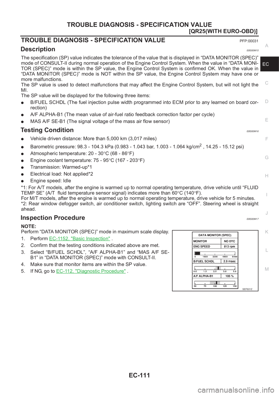
Perform “DATA MONITOR (SPEC)” mode in maximum scale display.
1. Perform EC-1152, "
Basic Inspection" .
2. Confirm that the testing conditions indicated above are met.
3. Select “B/FUEL SCHDL”, “A/F ALPHA-B1” and “MAS A/F SE-
B1” in “DATA MONITOR (SPEC)” mode with CONSULT-II.
4. Make sure that monitor items are within the SP value.
5. If NG, go to EC-112, "
Diagnostic Procedure" .
SEF601Z
Page 475 of 3833
DTC P0011 IVT CONTROL
EC-125
[QR25(WITH EURO-OBD)]
C
D
E
F
G
H
I
J
K
L
MA
EC
DTC P0011 IVT CONTROLPFP:23796
DescriptionEBS00M1K
SYSTEM DESCRIPTION
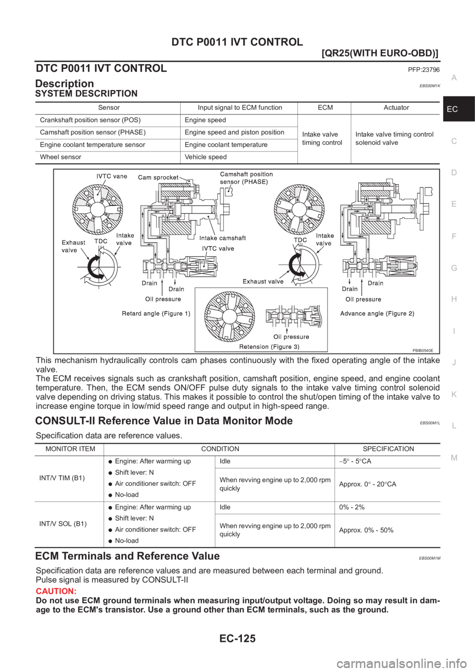
This mechanism hydraulically controls cam phases continuously with the fixed operating angle of the intake
valve.
The ECM receives signals such as crankshaft position, camshaft position, engine speed, and engine coolant
temperature. Then, the ECM sends ON/OFF pulse duty signals to the intake valve timing control solenoid
valve depending on driving status. This makes it possible to control the shut/open timing of the intake valve to
increase engine torque in low/mid speed range and output in high-speed range.
CONSULT-II Reference Value in Data Monitor ModeEBS00M1L
Specification data are reference values.
ECM Terminals and Reference ValueEBS00M1M
Specification data are reference values and are measured between each terminal and ground.
Pulse signal is measured by CONSULT-II
CAUTION:
Do not use ECM ground terminals when measuring input/output voltage. Doing so may result in dam-
age to the ECM's transistor. Use a ground other than ECM terminals, such as the ground.
Sensor Input signal to ECM function ECM Actuator
Crankshaft position sensor (POS) Engine speed
Intake valve
timing controlIntake valve timing control
solenoid valve Camshaft position sensor (PHASE) Engine speed and piston position
Engine coolant temperature sensor Engine coolant temperature
Wheel sensor Vehicle speed
PBIB0540E
MONITOR ITEM CONDITION SPECIFICATION
INT/V TIM (B1)
●Engine: After warming up
●Shift lever: N
●Air conditioner switch: OFF
●No-loadIdle−5° - 5°CA
When revving engine up to 2,000 rpm
quicklyApprox. 0° - 20°CA
INT/V SOL (B1)
●Engine: After warming up
●Shift lever: N
●Air conditioner switch: OFF
●No-loadIdle 0% - 2%
When revving engine up to 2,000 rpm
quicklyApprox. 0% - 50%
Page 510 of 3833
EC-160
[QR25(WITH EURO-OBD)]
DTC P0127 IAT SENSOR
DTC P0127 IAT SENSOR
PFP:22630
Component DescriptionEBS00M33
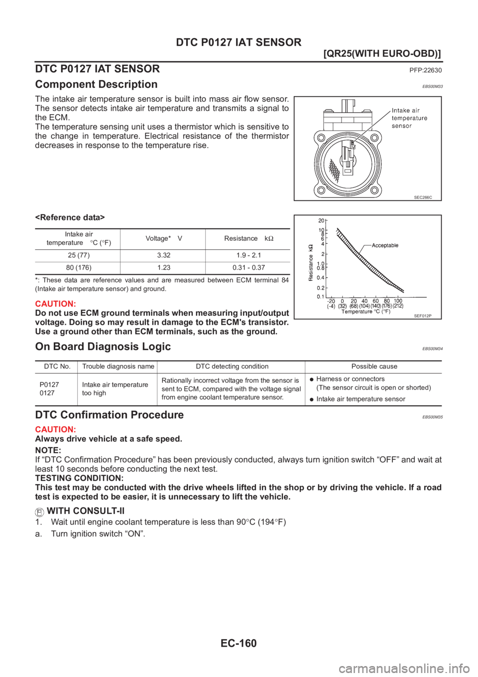
The intake air temperature sensor is built into mass air flow sensor.
The sensor detects intake air temperature and transmits a signal to
the ECM.
The temperature sensing unit uses a thermistor which is sensitive to
the change in temperature. Electrical resistance of the thermistor
decreases in response to the temperature rise.
*: These data are reference values and are measured between ECM terminal 84
(Intake air temperature sensor) and ground.
CAUTION:
Do not use ECM ground terminals when measuring input/output
voltage. Doing so may result in damage to the ECM's transistor.
Use a ground other than ECM terminals, such as the ground.
On Board Diagnosis LogicEBS00M34
DTC Confirmation ProcedureEBS00M35
CAUTION:
Always drive vehicle at a safe speed.
NOTE:
If “DTC Confirmation Procedure” has been previously conducted, always turn ignition switch “OFF” and wait at
least 10 seconds before conducting the next test.
TESTING CONDITION:
This test may be conducted with the drive wheels lifted in the shop or by driving the vehicle. If a road
test is expected to be easier, it is unnecessary to lift the vehicle.
WITH CONSULT-II
1. Wait until engine coolant temperature is less than 90°C (194°F)
a. Turn ignition switch “ON”.
SEC266C
Intake air
temperature°C (°F)Vo lta g e * V R e s i s ta n c e kΩ
25 (77) 3.32 1.9 - 2.1
80 (176) 1.23 0.31 - 0.37
SEF012P
DTC No. Trouble diagnosis name DTC detecting condition Possible cause
P0127
0127Intake air temperature
too highRationally incorrect voltage from the sensor is
sent to ECM, compared with the voltage signal
from engine coolant temperature sensor.
●Harness or connectors
(The sensor circuit is open or shorted)
●Intake air temperature sensor
Page 567 of 3833
DTC P0300 - P0304 MULTIPLE CYLINDER MISFIRE, NO. 1 - 4 CYLINDER MIS-
FIRE
EC-217
[QR25(WITH EURO-OBD)]
C
D
E
F
G
H
I
J
K
L
MA
EC
DTC P0300 - P0304 MULTIPLE CYLINDER MISFIRE, NO. 1 - 4 CYLINDER MIS-
FIRE
PFP:00000
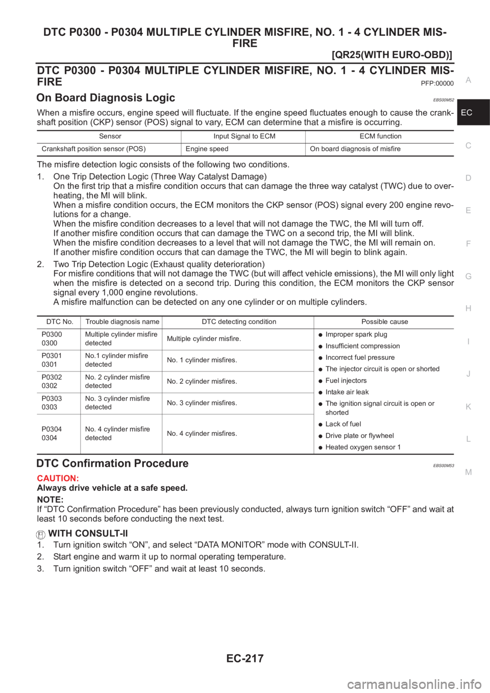
On Board Diagnosis LogicEBS00M52
When a misfire occurs, engine speed will fluctuate. If the engine speed fluctuates enough to cause the crank-
shaft position (CKP) sensor (POS) signal to vary, ECM can determine that a misfire is occurring.
The misfire detection logic consists of the following two conditions.
1. One Trip Detection Logic (Three Way Catalyst Damage)
On the first trip that a misfire condition occurs that can damage the three way catalyst (TWC) due to over-
heating, the MI will blink.
When a misfire condition occurs, the ECM monitors the CKP sensor (POS) signal every 200 engine revo-
lutions for a change.
When the misfire condition decreases to a level that will not damage the TWC, the MI will turn off.
If another misfire condition occurs that can damage the TWC on a second trip, the MI will blink.
When the misfire condition decreases to a level that will not damage the TWC, the MI will remain on.
If another misfire condition occurs that can damage the TWC, the MI will begin to blink again.
2. Two Trip Detection Logic (Exhaust quality deterioration)
For misfire conditions that will not damage the TWC (but will affect vehicle emissions), the MI will only light
when the misfire is detected on a second trip. During this condition, the ECM monitors the CKP sensor
signal every 1,000 engine revolutions.
A misfire malfunction can be detected on any one cylinder or on multiple cylinders.
DTC Confirmation ProcedureEBS00M53
CAUTION:
Always drive vehicle at a safe speed.
NOTE:
If “DTC Confirmation Procedure” has been previously conducted, always turn ignition switch “OFF” and wait at
least 10 seconds before conducting the next test.
WITH CONSULT-II
1. Turn ignition switch “ON”, and select “DATA MONITOR” mode with CONSULT-II.
2. Start engine and warm it up to normal operating temperature.
3. Turn ignition switch “OFF” and wait at least 10 seconds.
Sensor Input Signal to ECM ECM function
Crankshaft position sensor (POS) Engine speed On board diagnosis of misfire
DTC No. Trouble diagnosis name DTC detecting condition Possible cause
P0300
0300Multiple cylinder misfire
detectedMultiple cylinder misfire.
●Improper spark plug
●Insufficient compression
●Incorrect fuel pressure
●The injector circuit is open or shorted
●Fuel injectors
●Intake air leak
●The ignition signal circuit is open or
shorted
●Lack of fuel
●Drive plate or flywheel
●Heated oxygen sensor 1 P0301
0301No.1 cylinder misfire
detectedNo. 1 cylinder misfires.
P0302
0302No. 2 cylinder misfire
detectedNo. 2 cylinder misfires.
P0303
0303No. 3 cylinder misfire
detectedNo. 3 cylinder misfires.
P0304
0304No. 4 cylinder misfire
detectedNo. 4 cylinder misfires.
Page 600 of 3833
EC-250
[QR25(WITH EURO-OBD)]
DTC P0500 VSS
DTC P0500 VSS
PFP:32702
Component DescriptionEBS00M67
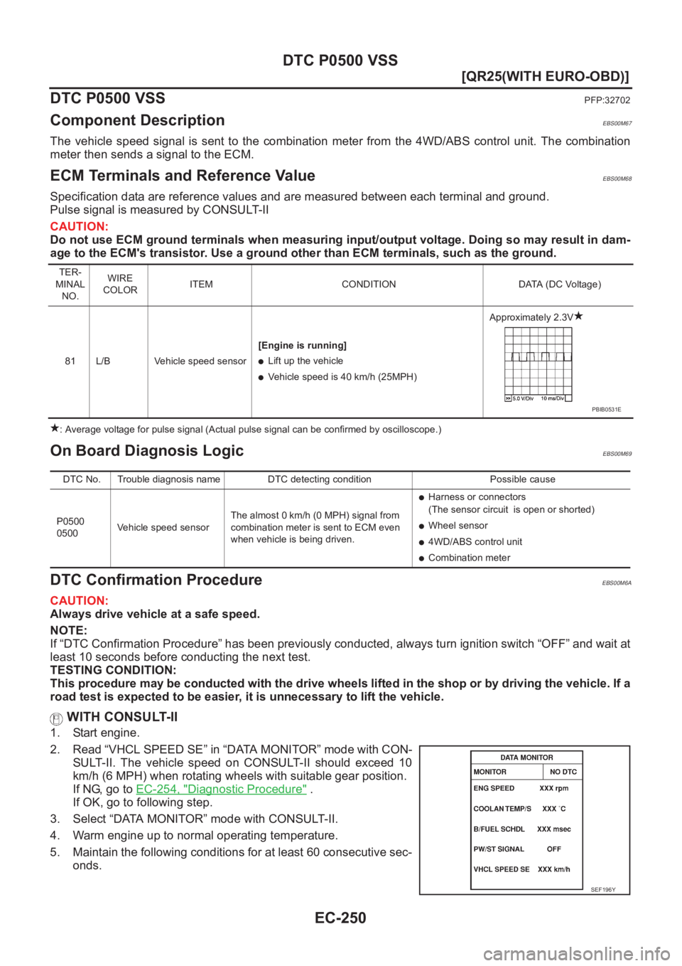
The vehicle speed signal is sent to the combination meter from the 4WD/ABS control unit. The combination
meter then sends a signal to the ECM.
ECM Terminals and Reference ValueEBS00M68
Specification data are reference values and are measured between each terminal and ground.
Pulse signal is measured by CONSULT-II
CAUTION:
Do not use ECM ground terminals when measuring input/output voltage. Doing so may result in dam-
age to the ECM's transistor. Use a ground other than ECM terminals, such as the ground.
: Average voltage for pulse signal (Actual pulse signal can be confirmed by oscilloscope.)
On Board Diagnosis LogicEBS00M69
DTC Confirmation ProcedureEBS00M6A
CAUTION:
Always drive vehicle at a safe speed.
NOTE:
If “DTC Confirmation Procedure” has been previously conducted, always turn ignition switch “OFF” and wait at
least 10 seconds before conducting the next test.
TESTING CONDITION:
This procedure may be conducted with the drive wheels lifted in the shop or by driving the vehicle. If a
road test is expected to be easier, it is unnecessary to lift the vehicle.
WITH CONSULT-II
1. Start engine.
2. Read “VHCL SPEED SE” in “DATA MONITOR” mode with CON-
SULT-II. The vehicle speed on CONSULT-II should exceed 10
km/h (6 MPH) when rotating wheels with suitable gear position.
If NG, go to EC-254, "
Diagnostic Procedure" .
If OK, go to following step.
3. Select “DATA MONITOR” mode with CONSULT-II.
4. Warm engine up to normal operating temperature.
5. Maintain the following conditions for at least 60 consecutive sec-
onds.
TER-
MINAL
NO.WIRE
COLORITEM CONDITION DATA (DC Voltage)
81 L/B Vehicle speed sensor[Engine is running]
●Lift up the vehicle
●Vehicle speed is 40 km/h (25MPH)Approximately 2.3V
PBIB0531E
DTC No. Trouble diagnosis name DTC detecting condition Possible cause
P0500
0500Vehicle speed sensorThe almost 0 km/h (0 MPH) signal from
combination meter is sent to ECM even
when vehicle is being driven.
●Harness or connectors
(The sensor circuit is open or shorted)
●Wheel sensor
●4WD/ABS control unit
●Combination meter
SEF196Y