fuel filter NISSAN X-TRAIL 2001 Service Repair Manual
[x] Cancel search | Manufacturer: NISSAN, Model Year: 2001, Model line: X-TRAIL, Model: NISSAN X-TRAIL 2001Pages: 3833, PDF Size: 39.49 MB
Page 9 of 3833

PRECAUTIONS
GI-7
C
D
E
F
G
H
I
J
K
L
MB
GI
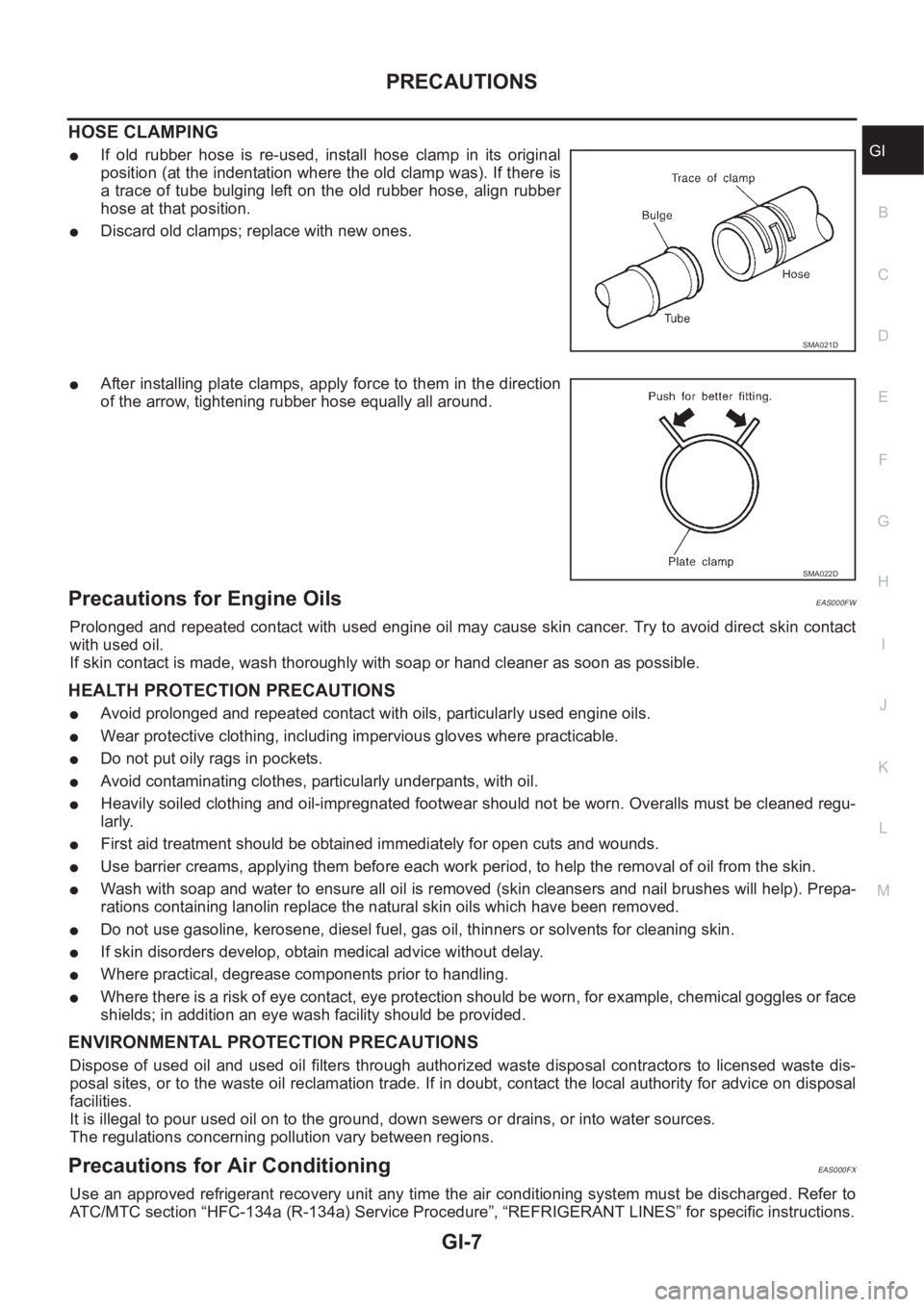
HOSE CLAMPING
●If old rubber hose is re-used, install hose clamp in its original
position (at the indentation where the old clamp was). If there is
a trace of tube bulging left on the old rubber hose, align rubber
hose at that position.
●Discard old clamps; replace with new ones.
●After installing plate clamps, apply force to them in the direction
of the arrow, tightening rubber hose equally all around.
Precautions for Engine OilsEAS000FW
Prolonged and repeated contact with used engine oil may cause skin cancer. Try to avoid direct skin contact
with used oil.
If skin contact is made, wash thoroughly with soap or hand cleaner as soon as possible.
HEALTH PROTECTION PRECAUTIONS
●Avoid prolonged and repeated contact with oils, particularly used engine oils.
●Wear protective clothing, including impervious gloves where practicable.
●Do not put oily rags in pockets.
●Avoid contaminating clothes, particularly underpants, with oil.
●Heavily soiled clothing and oil-impregnated footwear should not be worn. Overalls must be cleaned regu-
larly.
●First aid treatment should be obtained immediately for open cuts and wounds.
●Use barrier creams, applying them before each work period, to help the removal of oil from the skin.
●Wash with soap and water to ensure all oil is removed (skin cleansers and nail brushes will help). Prepa-
rations containing lanolin replace the natural skin oils which have been removed.
●Do not use gasoline, kerosene, diesel fuel, gas oil, thinners or solvents for cleaning skin.
●If skin disorders develop, obtain medical advice without delay.
●Where practical, degrease components prior to handling.
●Where there is a risk of eye contact, eye protection should be worn, for example, chemical goggles or face
shields; in addition an eye wash facility should be provided.
ENVIRONMENTAL PROTECTION PRECAUTIONS
Dispose of used oil and used oil filters through authorized waste disposal contractors to licensed waste dis-
posal sites, or to the waste oil reclamation trade. If in doubt, contact the local authority for advice on disposal
facilities.
It is illegal to pour used oil on to the ground, down sewers or drains, or into water sources.
The regulations concerning pollution vary between regions.
Precautions for Air Conditioning EAS000FX
Use an approved refrigerant recovery unit any time the air conditioning system must be discharged. Refer to
ATC/MTC section “HFC-134a (R-134a) Service Procedure”, “REFRIGERANT LINES” for specific instructions.
SMA021D
SMA022D
Page 51 of 3833

EM-1
ENGINE MECHANICAL
B ENGINE
CONTENTS
C
D
E
F
G
H
I
J
K
L
M
SECTION
A
EM
ENGINE MECHANICAL
QR
PRECAUTIONS .......................................................... 5
Precautions for Drain Engine Coolant ...................... 5
Precautions for Disconnecting Fuel Piping .............. 5
Precautions for Removal and Disassembly ............. 5
Precautions for Inspection, Repair and Replace-
ment ......................................................................... 5
Precautions for Assembly and Installation ............... 5
Parts Requiring Angular Tightening ......................... 5
Precautions For Liquid Gasket ................................. 6
REMOVAL OF LIQUID GASKET .......................... 6
LIQUID GASKET APPLICATION PROCEDURE ..... 6
PREPARATION ........................................................... 7
Special Service Tools ............................................... 7
Commercial Service Tools ........................................ 8
NOISE, VIBRATION, AND HARSHNESS (NVH)
TROUBLESHOOTING .............................................. 10
NVH Troubleshooting —Engine Noise ................... 10
Use the Chart Below to Help You Find the Cause
of the Symptom. ...................................................... 11
DRIVE BELTS ........................................................... 12
Checking Drive Belts .............................................. 12
Tension Adjustment ................................................ 12
Removal and Installation ........................................ 12
REMOVAL ........................................................... 12
INSTALLATION ................................................... 13
Removal and Installation of Drive Belt Auto-Ten-
sioner ..................................................................... 13
REMOVAL ........................................................... 13
INSTALLATION ................................................... 13
AIR CLEANER AND AIR DUCT ............................... 14
Removal and Installation ........................................ 14
REMOVAL ........................................................... 14
INSTALLATION ................................................... 14
CHANGING AIR CLEANER FILTER ................... 15INTAKE MANIFOLD ................................................. 16
Removal and Installation ........................................ 16
QR20DE .............................................................. 16
QR25DE .............................................................. 17
REMOVAL ........................................................... 17
INSPECTION AFTER REMOVAL ....................... 20
INSTALLATION ................................................... 20
INSPECTION AFTER INSTALLATION ................ 22
EXHAUST MANIFOLD AND THREE WAY CATA-
LYST .......................................................................... 24
Removal and Installation ........................................ 24
REMOVAL ........................................................... 24
INSPECTION AFTER REMOVAL ....................
... 25
INSTALLATION ................................................... 25
OIL PAN AND OIL STRAINER ................................. 26
Removal and Installation ........................................ 26
REMOVAL ........................................................... 26
INSPECTION AFTER REMOVAL ....................... 27
INSTALLATION ................................................... 27
INSPECTION AFTER INSTALLATION ................ 28
IGNITION COIL ......................................................... 29
Removal and Installation ........................................ 29
REMOVAL ........................................................... 29
INSTALLATION ................................................... 29
SPARK PLUG ........................................................... 30
Removal and Installation ........................................ 30
REMOVAL ........................................................... 30
INSPECTION AFTER REMOVAL ....................... 30
INSTALLATION ................................................... 31
FUEL INJECTOR AND FUEL TUBE ........................ 32
Removal and Installation ........................................ 32
QR20DE .............................................................. 32
QR25DE .............................................................. 32
REMOVAL ........................................................... 33
INSTALLATION ................................................... 33
INSPECTION AFTER INSTALLATION ................ 34
ROCKER COVER ..................................................... 35
Removal and Installation ........................................ 35
REMOVAL ........................................................... 35
INSTALLATION ................................................... 36
Page 53 of 3833

EM-3
C
D
E
F
G
H
I
J
K
L
M
EMA Parts Requiring Angular Tightening ...................... 110
Precautions For Liquid Gasket ............................. . 111
REMOVAL OF LIQUID GASKET ...................... . 111
LIQUID GASKET APPLICATION PROCEDURE . . 111
PREPARATION ........................................................112
Special Service Tools ............................................ 112
Commercial Service Tools ..................................... 115
NOISE, VIBRATION, AND HARSHNESS (NVH)
TROUBLESHOOTING .............................................116
NVH Troubleshooting —Engine Noise .................. 116
Use the Chart Below to Help You Find the Cause
of the Symptom. .................................................... 117
DRIVE BELTS ..........................................................118
Checking Drive Belts ............................................. 118
Tension Adjustment ............................................... 118
AIR CONDITIONER COMPRESSOR BELT ...... 119
ALTERNATOR AND WATER PUMP BELT ........ 119
Removal and Installation ....................................... 119
REMOVAL .......................................................... 119
INSTALLATION .................................................. 119
AIR CLEANER AND AIR DUCT ............................. 120
Removal and Installation ...................................... 120
REMOVAL ......................................................... 120
INSTALLATION ................................................. 120
CHANGING AIR CLEANER FILTER ................. 121
CHARGE AIR COOLER ......................................... 122
Removal and Installation ...................................... 122
REMOVAL ......................................................... 122
INSPECTION AFTER REMOVAL ..................... 122
INSTALLATION ................................................. 122
INTAKE MANIFOLD ............................................... 123
Removal and Installation ...................................... 123
REMOVAL ......................................................... 123
INSPECTION AFTER REMOVAL ..................... 124
INSTALLATION ................................................. 124
INSPECTION AFTER INSTALLATION ............. 125
CATALYST .............................................................. 126
Removal and Installation ...................................... 126
REMOVAL ......................................................... 126
INSTALLATION ................................................. 126
EXHAUST MANIFOLD AND TURBOCHARGER .. 127
Removal and Installation ...................................... 127
REMOVAL ......................................................... 127
INSTALLATION ................................................. 128
INSPECTION AFTER INSTALLATION ............. 128
Disassembly and Assembly ................................. 129
REMOVAL ......................................................... 129
INSPECTION AFTER REMOVAL ..................... 129
Turbocharger ........................................................ 130
ROTOR SHAFT CLEARANCE ......................... 130
ROTOR SHAFT END PLAY .............................. 130
TURBINE WHEEL ............................................. 131
COMPRESSOR WHEEL .................................. 131
WASTEGATE VALVE ACTUATOR ................... 131
TROUBLE DIAGNOSIS OF TURBOCHARGER . 132OIL PAN AND OIL STRAINER ...............................133
Removal and Installation ......................................133
REMOVAL .........................................................133
INSPECTION AFTER REMOVAL .....................135
INSTALLATION .................................................135
INSPECTION AFTER INSTALLATION ..............137
GLOW PLUG ..........................................................138
Removal and Installation ......................................138
REMOVAL .........................................................138
INSTALLATION .................................................138
VACUUM PUMP ......................................................139
Removal and Installation ......................................139
MODELS PRODUCED BEFORE MARCH 2001 .139
MODELS PRODUCED SINCE APRIL 2001 .....140
INSPECTION BEFORE REMOVAL ..................140
REMOVAL .........................................................140
INSTALLATION .................................................141
INSPECTION AFTER INSTALLATION ..............142
Disassembly and Assembly ..................................142
DISASSEMBLY .................................................142
ASSEMBLY .......................................................142
INJECTION TUBE AND FUEL INJECTOR ............144
Removal and Installation ......................................144
REMOVAL .........................................................144
INSTALLATION .................................................145
INSPECTION AFTER INSTALLATION ..............146
FUEL SUPPLY PUMP .............................................147
Removal and Installation ......................................147
REMOVAL .........................................................147
INSPECTION AFTER REMOVAL .....................152
INSTALLATION .................................................152
ROCKER COVER ...................................................156
Removal and Installation ......................................156
REMOVAL .........................................................156
INSTALLATION .................................................157
INSPECTION AFTER INSTALLATION .............
.157
CAMSHAFT ............................................................158
Removal and Installation ......................................158
REMOVAL .........................................................158
INSPECTION AFTER REMOVAL .....................159
INSTALLATION .................................................162
Valve Clearance ...................................................163
INSPECTION ....................................................163
ADJUSTMENTS ................................................164
SECONDARY TIMING CHAIN ................................167
Removal and Installation ......................................167
REMOVAL .........................................................167
INSPECTION AFTER REMOVAL .....................169
INSTALLATION .................................................170
PRIMARY TIMING CHAIN ......................................172
Removal and Installation ......................................172
REMOVAL .........................................................174
INSPECTION AFTER REMOVAL .....................177
INSTALLATION .................................................177
CYLINDER HEAD .................................................. .182
On-Vehicle Service ...............................................182
CHECKING COMPRESSION PRESSURE .......182
Removal and Installation ......................................183
REMOVAL .........................................................183
Page 224 of 3833
![NISSAN X-TRAIL 2001 Service Repair Manual EM-174
[YD22DDTi]
PRIMARY TIMING CHAIN
REMOVAL
1. Remove engine coolant reservoir tank.
2. Remove charge air cooler and bracket. Refer to EM-122, "
Removal and Installation" .
3. Remove air cl NISSAN X-TRAIL 2001 Service Repair Manual EM-174
[YD22DDTi]
PRIMARY TIMING CHAIN
REMOVAL
1. Remove engine coolant reservoir tank.
2. Remove charge air cooler and bracket. Refer to EM-122, "
Removal and Installation" .
3. Remove air cl](/img/5/57405/w960_57405-223.png)
EM-174
[YD22DDTi]
PRIMARY TIMING CHAIN
REMOVAL
1. Remove engine coolant reservoir tank.
2. Remove charge air cooler and bracket. Refer to EM-122, "
Removal and Installation" .
3. Remove air cleaner and air duct. Refer to EM-120, "
Removal and Installation" .
4. Remove rocker cover. Refer to EM-156, "
Removal and Installation" .
5. Remove RH engine mount insulator and bracket. Refer to EM-193, "
Removal and Installation" .
6. Pull power steering reservoir tank out of brackets to move power steering piping.
CAUTION:
To avoid removing power steering reservoir tank out of brackets move it with power steering pip-
ing aside.
7. Remove oil pan. Refer to EM-133, "
Removal and Installation" .
8. Remove oil filter bracket. Refer to LU-22, "
OIL FILTER BRACKET" .
9. Remove injection tube and fuel injector. Refer to EM-144, "
Removal and Installation" .
10. Remove secondary timing chain and associated parts. Refer to EM-167, "
Removal and Installation" .
11. When removing rear chain case, remove camshaft sprockets. Refer to EM-158, "
Removal and Installa-
tion" .
12. Remove crankshaft pulley.
a. Hold crankshaft pulley with the pulley holder (SST).
b. Loosen crankshaft pulley fixing bolt and pull out the bolt approx-
imately 10 mm (0.39 in).
c. Using pulley puller (SST), remove crankshaft pulley.
●Use two M6 bolts with approx. 60 mm (2.36 in) shank length
for securing crankshaft pulley.
13. Remove oil pump housing.
●Loosen bolts in the reverse order of that shown in the figure
and remove them.
●Use seal cutter (SST) etc. for removal.
14. Remove front oil seal from oil pump housing.
●Punch out the seal off from the back surface of the oil pump
using a flat-bladed screwdriver.
●Be careful not to damage the oil pump housing.
7. Chain guide 8. Spacer 9. Front chain case
10. Crankshaft pulley 11. Front oil seal 12. Oil pump housing
13. Primary timing chain 14. Oil pump drive spacer 15. Crankshaft sprocket
16. Secondary timing chain 17. Rear chain case 18. Power steering pump
JEM131G
JEM132G
JEM133G
Page 367 of 3833

EC-17
C
D
E
F
G
H
I
J
K
L
M
ECA INJECTOR CIRCUIT ..............................................1357
Component Description .......................................1357
CONSULT-II Reference Value in Data Monitor Mode
1357
ECM Terminals and Reference Value .................1357
Wiring Diagram ...................................................1358
Diagnostic Procedure ..........................................1359
Component Inspection ........................................1361
Removal and Installation .....................................1361
START SIGNAL .....................................................1362
CONSULT-II Reference Value in Data Monitor Mode
1362
ECM Terminals and Reference Value .................1362
Wiring Diagram ...................................................1363
Diagnostic Procedure ..........................................1364
FUEL PUMP CIRCUIT ...........................................1366
Description ..........................................................1366
CONSULT-II Reference Value in Data Monitor Mode
1366
ECM Terminals and Reference Value .................1366
Wiring Diagram ...................................................1368
Diagnostic Procedure ..........................................1369
Component Inspection ........................................1371
Removal and Installation .....................................1372
REFRIGERANT PRESSURE SENSOR ................1373
Component Description .......................................1373
ECM Terminals and Reference Value .................1373
Wiring Diagram ...................................................1374
Diagnostic Procedure ..........................................1375
Removal and Installation .....................................1376
ELECTRICAL LOAD SIGNAL ...............................1377
CONSULT-II Reference Value in Data Monitor Mode
1377
ECM Terminals and Reference Value .................1377
Wiring Diagram ...................................................1378
Diagnostic Procedure ..........................................1380
DATA LINK CONNECTOR ....................................1385
Wiring Diagram ...................................................1385
EVAPORATIVE EMISSION SYSTEM ....................1386
Description ..........................................................1386
Component Inspection ........................................1388
POSITIVE CRANKCASE VENTILATION ..............1389
Description ..........................................................1389
Component Inspection ........................................1389
SERVICE DATA AND SPECIFICATIONS (SDS) ...1391
Fuel Pressure ......................................................1391
Idle Speed and Ignition Timing ............................1391
Calculated Load Value ........................................1391
Mass Air Flow Sensor .........................................1391
Intake Air Temperature Sensor ...........................1391
Engine Coolant Temperature Sensor ..................1391
Heated Oxygen Sensor 1 Heater ........................1391
Heated Oxygen sensor 2 Heater .........................1391
Crankshaft Position Sensor (POS) ......................1391
Camshaft Position Sensor (PHASE) ...................1391
Throttle Control Motor ......................................... 1392
Injector ................................................................1392
Fuel Pump ...........................................................1392
YD
INDEX FOR DTC ....................................................1393
Alphabetical Index ...............................................1393
DTC No. Index .....................................................1393
PRECAUTIONS .....................................................1395
Precautions for Supplemental Restraint System
(SRS) “AIR BAG” and “SEAT BELT PRE-TEN-
SIONER” ..............................................................1395
Precautions ..........................................................1395
Wiring Diagrams and Trouble Diagnosis .............1397
ENGINE CONTROL SYSTEM ...............................1398
System Diagram ..................................................1398
System Chart .......................................................1399
Fuel Injection Control System ..............................1399
Fuel Injection Timing Control System ..................1401
Air Conditioning Cut Control ................................1401
F u e l C u t C o n t r o l ( A t N o L o a d & H i g h E n g i n e S p e e d ) 1401
Crankcase Ventilation System .............................1402
CAN Communication ...........................................1402
BASIC SERVICE PROCEDURE ............................1404
Fuel Filter .............................................................1404
Accelerator Pedal Released Position Learning ...1404
Fuel Pressure Relief Valve ..................................1405
ON BOARD DIAGNOSTIC (OBD) SYSTEM .........1406
DTC and MI Detection Logic ...............................1406
Diagnostic Trouble Code (DTC) ..........................1406
NATS (Nissan Anti-theft System) ........................1406
Malfunction Indicator (MI) ....................................1407
TROUBLE DIAGNOSIS .........................................1409
Trouble Diagnosis Introduction ............................1409
Basic Inspection ..................................................1412
Symptom Matrix Chart .........................................1416
Engine Control Component Parts Location .........1420
Circuit Diagram ....................................................1423
ECM Harness Connector Terminal Layout ..........1425
ECM Terminals And Reference Value .................1425
CONSULT-II Function ..........................................1431
CONSULT-II Reference Value in Data Monitor Mode
1437
Major Sensor Reference Graph in Data Monitor
Mode ....................................................................1440
TROUBLE DIAGNOSIS FOR INTERMITTENT INCI-
DENT ......................................................................1441
Description ...........................................................1441
Diagnostic Procedure ..........................................1441
POWER SUPPLY CIRCUIT FOR ECM ..................1442
ECM Terminals and Reference Value ..................1442
Wiring Diagram ....................................................1443
Diagnostic Procedure ..........................................1444
Component Inspection .........................................1447
DTC U1000 CAN COMMUNICATION LINE ...........1448
Description ...........................................................1448
On Board Diagnosis Logic ...................................1448
DTC Confirmation Procedure ..............................1448
Wiring Diagram ....................................................1449
Diagnostic Procedure ..........................................1450
DTC P0100 MASS AIR FLOW SENSOR (MAFS) .1451
Component Description .......................................1451
Page 393 of 3833
![NISSAN X-TRAIL 2001 Service Repair Manual BASIC SERVICE PROCEDURE
EC-43
[QR25(WITH EURO-OBD)]
C
D
E
F
G
H
I
J
K
L
MA
EC
4. Install the fuel pressure gauge as shown in the figure.
●Wipe off oil or dirt from hose insertion part using clot NISSAN X-TRAIL 2001 Service Repair Manual BASIC SERVICE PROCEDURE
EC-43
[QR25(WITH EURO-OBD)]
C
D
E
F
G
H
I
J
K
L
MA
EC
4. Install the fuel pressure gauge as shown in the figure.
●Wipe off oil or dirt from hose insertion part using clot](/img/5/57405/w960_57405-392.png)
BASIC SERVICE PROCEDURE
EC-43
[QR25(WITH EURO-OBD)]
C
D
E
F
G
H
I
J
K
L
MA
EC
4. Install the fuel pressure gauge as shown in the figure.
●Wipe off oil or dirt from hose insertion part using cloth moist-
ened with gasoline.
●Apply proper amount of gasoline between top of the fuel tube
and No.1 spool.
●Insert fuel hose for fuel pressure check until it touches the
No.1 spool on fuel tube.
●Use NISSAN genuine hose clamp (part number: 16439
N4710 or 16439 40U00).
●When reconnecting fuel line, always use new clamps.
●When reconnecting fuel hose, check the original fuel hose for
damage and abnormality.
●Use a torque driver to tighten clamps.
●Install hose clamp to the position within 1 - 2 mm (0.04 - 0.08
in).
●Make sure that clamp screw does not contact adjacent parts.
5. After connecting fuel hose for fuel pressure check, pull the hose
with a force of approximately 98 N (10 kg, 22 lb) to confirm fuel
tube does not come off.
6. Turn ignition switch “ON”, and check for fuel leakage.
7. Start engine and check for fuel leakage.
8. Read the indication of fuel pressure gauge.
●Do not perform fuel pressure check with system operating. Fuel pressure gauge may indicate false
readings.
●During fuel pressure check, confirm for fuel leakage from fuel connection every 3 minutes.
9. If result is unsatisfactory, go to next step.
10. Check the following.
●Fuel hoses and fuel tubes for clogging
●Fuel filter for clogging
●Fuel pump
●Fuel pressure regulator for clogging
If OK, replace fuel pressure regulator.
If NG, repair or replace.Tightening torque: 1 - 1.5 N·m (0.1 - 0.15 kg-m,
9 - 13 in-lb)
At idling:
Approximately 350 kPa (3.5 bar, 3.57 kg/cm
2 , 51 psi)
PBIB0669E
PBIB0670E
Page 430 of 3833
![NISSAN X-TRAIL 2001 Service Repair Manual EC-80
[QR25(WITH EURO-OBD)]
TROUBLE DIAGNOSIS
1 - 6: The numbers refer to the order of inspection.Va l v e
mecha-
nismTiming chain
55555 55 5EM-37
CamshaftEM-46
Intake valve
3EM-59
Exhaust valve
Exh NISSAN X-TRAIL 2001 Service Repair Manual EC-80
[QR25(WITH EURO-OBD)]
TROUBLE DIAGNOSIS
1 - 6: The numbers refer to the order of inspection.Va l v e
mecha-
nismTiming chain
55555 55 5EM-37
CamshaftEM-46
Intake valve
3EM-59
Exhaust valve
Exh](/img/5/57405/w960_57405-429.png)
EC-80
[QR25(WITH EURO-OBD)]
TROUBLE DIAGNOSIS
1 - 6: The numbers refer to the order of inspection.Va l v e
mecha-
nismTiming chain
55555 55 5EM-37
CamshaftEM-46
Intake valve
3EM-59
Exhaust valve
Exhaust Exhaust manifold/Tube/Muffler/
Gasket
55555 55 5EM-24
,EX-
2Three way catalyst
Lubrica-
tionOil pan/Oil strainer/Oil pump/Oil
filter/Oil gallery/Oil cooler
55555 55 52EM-26
,LU-
9 , LU-10 ,
LU-13
Oil level (Low)/Filthy oilLU-7
Cooling Radiator/Hose/Radiator filler cap
55555 55 25CO-11
Thermostat 5CO-20
Water pumpCO-18
Water galleryCO-7
Cooling fan 5CO-11
Coolant level (low)/Contaminated
coolantCO-9
NATS (Nissan Anti-theft System) 1 1EC-58 or
BL-80
SYMPTOM
Reference
page
HARD/NO START/RESTART (EXCP. HA)
ENGINE STALL
HESITATION/SURGING/FLAT SPOT
SPARK KNOCK/DETONATION
LACK OF POWER/POOR ACCELERATION
HIGH IDLE/LOW IDLE
ROUGH IDLE/HUNTING
IDLING VIBRATION
SLOW/NO RETURN TO IDLE
OVERHEATS/WATER TEMPERATURE HIGH
EXCESSIVE FUEL CONSUMPTION
EXCESSIVE OIL CONSUMPTION
BATTERY DEAD (UNDER CHARGE)
Warranty symptom code AA AB AC AD AE AF AG AH AJ AK AL AM HA
Page 761 of 3833
![NISSAN X-TRAIL 2001 Service Repair Manual FUEL PUMP CIRCUIT
EC-411
[QR25(WITH EURO-OBD)]
C
D
E
F
G
H
I
J
K
L
MA
EC
FUEL PUMP
1. Disconnect fuel level sensor unit and fuel pump harness connector.
2. Check resistance between fuel level sen NISSAN X-TRAIL 2001 Service Repair Manual FUEL PUMP CIRCUIT
EC-411
[QR25(WITH EURO-OBD)]
C
D
E
F
G
H
I
J
K
L
MA
EC
FUEL PUMP
1. Disconnect fuel level sensor unit and fuel pump harness connector.
2. Check resistance between fuel level sen](/img/5/57405/w960_57405-760.png)
FUEL PUMP CIRCUIT
EC-411
[QR25(WITH EURO-OBD)]
C
D
E
F
G
H
I
J
K
L
MA
EC
FUEL PUMP
1. Disconnect fuel level sensor unit and fuel pump harness connector.
2. Check resistance between fuel level sensor unit and fuel pump
terminals 3 and 5.
CONDENSER
1. Turn ignition switch “OFF”.
2. Disconnect condenser harness connector.
3. Check resistance between condenser terminals 1 and 2.
Removal and InstallationEBS00MBL
FUEL PUMP
Refer to FL-4, "FUEL LEVEL SENSOR UNIT, FUEL FILTER AND FUEL PUMP ASSEMBLY" . Resistance: Approximately 1.0Ω [at 25°C (77°F)]
PBIB0658E
Resistance: Above 1MΩ [at 25°C (77°F)]
SEF124Y
Page 803 of 3833
![NISSAN X-TRAIL 2001 Service Repair Manual BASIC SERVICE PROCEDURE
EC-453
[QR25(WITHOUT EURO-OBD)]
C
D
E
F
G
H
I
J
K
L
MA
EC
●Do not twist or kink fuel hose because it is plastic hose.
●Do not remove fuel hose from quick connector.
●Keep NISSAN X-TRAIL 2001 Service Repair Manual BASIC SERVICE PROCEDURE
EC-453
[QR25(WITHOUT EURO-OBD)]
C
D
E
F
G
H
I
J
K
L
MA
EC
●Do not twist or kink fuel hose because it is plastic hose.
●Do not remove fuel hose from quick connector.
●Keep](/img/5/57405/w960_57405-802.png)
BASIC SERVICE PROCEDURE
EC-453
[QR25(WITHOUT EURO-OBD)]
C
D
E
F
G
H
I
J
K
L
MA
EC
●Do not twist or kink fuel hose because it is plastic hose.
●Do not remove fuel hose from quick connector.
●Keep the original fuel hose to be free from intrusion of dust or foreign substances with a suitable cover.
4. Install the fuel pressure gauge as shown in the figure.
●Wipe off oil or dirt from hose insertion part using cloth moist-
ened with gasoline.
●Apply proper amount of gasoline between top of the fuel tube
and No.1 spool.
●Insert fuel hose for fuel pressure check until it touches the
No.1 spool on fuel tube.
●Use NISSAN genuine hose clamp (part number: 16439
N4710 or 16439 40U00).
●When reconnecting fuel line, always use new clamps.
●When reconnecting fuel hose, check the original fuel hose for
damage and abnormality.
●Use a torque driver to tighten clamps.
●Install hose clamp to the position within 1 - 2 mm (0.04 - 0.08
in).
●Make sure that clamp screw does not contact adjacent parts.
5. After connecting fuel hose for fuel pressure check, pull the hose
with a force of approximately 98 N (10 kg, 22 lb) to confirm fuel
tube does not come off.
6. Turn ignition switch “ON”, and check for fuel leakage.
7. Start engine and check for fuel leakage.
8. Read the indication of fuel pressure gauge.
●Do not perform fuel pressure check with system operating. Fuel pressure gauge may indicate false
readings.
●During fuel pressure check, confirm for fuel leakage from fuel connection every 3 minutes.
9. If result is unsatisfactory, go to next step.
10. Check the following.
●Fuel hoses and fuel tubes for clogging
●Fuel filter for clogging
●Fuel pump
●Fuel pressure regulator for clogging
If OK, replace fuel pressure regulator.
If NG, repair or replace.Tightening
torque: 1 - 1.5 N·m (0.1 - 0.15 kg-m, 9 - 13
in-lb)
At idling: Approximately 350 kPa (3.5 bar, 3.57 kg/cm
2 , 51
psi)
PBIB0669E
PBIB0670E
Page 822 of 3833
![NISSAN X-TRAIL 2001 Service Repair Manual EC-472
[QR25(WITHOUT EURO-OBD)]
TROUBLE DIAGNOSIS
1 - 6: The numbers refer to the order of inspection.
(continued on next page)Exhaust Exhaust manifold/Tube/Muffler/
Gasket
55555 55 5EM-24
,EX-
2Three NISSAN X-TRAIL 2001 Service Repair Manual EC-472
[QR25(WITHOUT EURO-OBD)]
TROUBLE DIAGNOSIS
1 - 6: The numbers refer to the order of inspection.
(continued on next page)Exhaust Exhaust manifold/Tube/Muffler/
Gasket
55555 55 5EM-24
,EX-
2Three](/img/5/57405/w960_57405-821.png)
EC-472
[QR25(WITHOUT EURO-OBD)]
TROUBLE DIAGNOSIS
1 - 6: The numbers refer to the order of inspection.
(continued on next page)Exhaust Exhaust manifold/Tube/Muffler/
Gasket
55555 55 5EM-24
,EX-
2Three way catalyst
Lubrica-
tionOil pan/Oil strainer/Oil pump/Oil
filter/Oil gallery/Oil cooler
55555 55 52EM-26
,LU-
9 , LU-10 ,
LU-13
Oil level (Low)/Filthy oilLU-7
Cooling Radiator/Hose/Radiator filler cap
55555 55 25CO-11
Thermostat 5CO-20
Water pumpCO-18
Water galleryCO-7
Cooling fan 5CO-11
Coolant level (low)/Contaminated
coolantCO-9
NATS (Nissan Anti-theft System) 1 1EC-456 or
BL-80
SYMPTOM
Reference
page
HARD/NO START/RESTART (EXCP. HA)
ENGINE STALL
HESITATION/SURGING/FLAT SPOT
SPARK KNOCK/DETONATION
LACK OF POWER/POOR ACCELERATION
HIGH IDLE/LOW IDLE
ROUGH IDLE/HUNTING
IDLING VIBRATION
SLOW/NO RETURN TO IDLE
OVERHEATS/WATER TEMPERATURE HIGH
EXCESSIVE FUEL CONSUMPTION
EXCESSIVE OIL CONSUMPTION
BATTERY DEAD (UNDER CHARGE)
Warranty symptom code AA AB AC AD AE AF AG AH AJ AK AL AM HA