coolant reservoir NISSAN X-TRAIL 2003 Electronic Owner's Manual
[x] Cancel search | Manufacturer: NISSAN, Model Year: 2003, Model line: X-TRAIL, Model: NISSAN X-TRAIL 2003Pages: 3066, PDF Size: 51.47 MB
Page 2032 of 3066
![NISSAN X-TRAIL 2003 Electronic Owners Manual EM-62
[QR20DE]
ENGINE ASSEMBLY
1. Release fuel pressure. Refer toEC-34, "FUEL PRESSURE RELEASE"(WITH EURO-OBD),EC-399,
"FUEL PRESSURE RELEASE"(WITHOUT EURO-OBD).
2. Remove engine hood.
3. Drain coolan](/img/5/57402/w960_57402-2031.png "NISSAN X-TRAIL 2003 Electronic Owners Manual EM-62
[QR20DE]
ENGINE ASSEMBLY
1. Release fuel pressure. Refer toEC-34, \"FUEL PRESSURE RELEASE\"(WITH EURO-OBD),EC-399,
\"FUEL PRESSURE RELEASE\"(WITHOUT EURO-OBD).
2. Remove engine hood.
3. Drain coolan")
EM-62
[QR20DE]
ENGINE ASSEMBLY
1. Release fuel pressure. Refer toEC-34, "FUEL PRESSURE RELEASE"(WITH EURO-OBD),EC-399,
"FUEL PRESSURE RELEASE"(WITHOUT EURO-OBD).
2. Remove engine hood.
3. Drain coolant from radiator drain plug.
4. Remove the following parts.
lLH/RH under cover
lLH/RH Front wheel
lBattery
lAuxiliary drive belt; Refer toEM-14, "Removal and Installation of Auxiliary Drive Belt Auto- tensioner".
lAir duct and air cleaner case assembly; Refer toEM-15, "Removal and Installation".
lAlternator
lRadiator and radiator fan assembly; Refer toCO-12, "RADIATOR".
5. Disconnect engine room harness from the engine side and set it aside for easier work.
6. Disconnect all the body-side vacuum hoses and air hoses at engine side.
Engine room LH
7. Disconnect fuel hose, and plug it to prevent fuel from draining. Refer toEM-17, "
INTAKE MANIFOLD"
8. Disconnect heater hose, and install plug it to prevent engine coolant from draining.
9. Disconnect select cable from transaxle (A/T models).
10. Remove clutch operating cylinder from transaxle, and move it aside (M/T models).
11. Disconnect shift cable from transaxle (M/T models).
Engine room RH
12. Remove engine coolant reservoir tank.
13. Remove air conditioner compressor with piping connected from engine. Temporarily secure it on body
with a rope to avoid putting load on it.
Vehicle underbody
14. Remove exhaust front tube.
15. Remove propeller shaft.
16. Remove steering shaft from steering gear.
17. Disconnect power steering fluid cooler piping at a point between body and engine.
18. Remove ABS sensor from brake caliper.
19. Remove brake caliper with piping connected from steering knuckle. Temporarily secure it on body with a
rope to avoid load on it.
20. Remove LH/RH suspension from steering knuckle under strut.
Removal
21. Install engine slingers into front left of cylinder head and rear right of cylinder head.
lUse alternator bracket mounting bolt holes for the frontside.
22. Lift with hoist and secure the engine in position.Slinger bolts:
Front: 51.0 - 64.7 N·m (5.2 - 6.6 kg-m, 38 - 47 ft-lb)
Rear: 24.5 - 31.4 N·m (2.5 - 3.2 kg-m, 18 - 23 ft-lb)
KBIA0255E
Page 2108 of 3066
![NISSAN X-TRAIL 2003 Electronic Owners Manual EM-138
[YD22DDTi]
FUEL SUPPLY PUMP
FUEL SUPPLY PUMP
PFP:00018
Removal and InstallationEBS00CBL
CAUTION:
lbefore removing and installing fuel supply pump, be sure to remove sprocket. Do not loosen or
r](/img/5/57402/w960_57402-2107.png "NISSAN X-TRAIL 2003 Electronic Owners Manual EM-138
[YD22DDTi]
FUEL SUPPLY PUMP
FUEL SUPPLY PUMP
PFP:00018
Removal and InstallationEBS00CBL
CAUTION:
lbefore removing and installing fuel supply pump, be sure to remove sprocket. Do not loosen or
r")
EM-138
[YD22DDTi]
FUEL SUPPLY PUMP
FUEL SUPPLY PUMP
PFP:00018
Removal and InstallationEBS00CBL
CAUTION:
lbefore removing and installing fuel supply pump, be sure to remove sprocket. Do not loosen or
remove installation nut in the center of fuel supply pump. If loosened or removed, replace fuel
supply pump.
lAfter removing timing chain, do not turn crankshaft and camshaft separately, or valves will strike
piston heads.
lWhen installing camshafts, chain tensioners, oil seals, or other sliding parts, lubricate contacting
surfaces with new engine oil.
lApply new engine oil to parts marked in illustration before installation.
REMOVAL
1. Remove coolant reservoir tank.
2. Remove charge air cooler. Refer toEM-114, "
Removal and Installation".
3. Remove RH engine mount insulator and bracket. Refer toEM-184, "
Removal and Installation".
4. Pull power steering reservoir tank out of brackets to move power steering piping.
CAUTION:
To avoid removing power steering reservoir tank out of brackets move it with power steering pip-
ing aside.
1. Washer 2. Fuel supply pump sprocket 3. Fuel supply pump
4. Fuel supply pump rear bracket 5. Fuel connector (Feed side) 6. Fuel connector (Return side)
SBIA0213E
Page 2128 of 3066
![NISSAN X-TRAIL 2003 Electronic Owners Manual EM-158
[YD22DDTi]
SECONDARY TIMING CHAIN
SECONDARY TIMING CHAIN
PFP:13028
Removal and InstallationEBS00BOG
CAUTION:
lAfter removing timing chain, do not turn crankshaft and camshaft separately, or val](/img/5/57402/w960_57402-2127.png "NISSAN X-TRAIL 2003 Electronic Owners Manual EM-158
[YD22DDTi]
SECONDARY TIMING CHAIN
SECONDARY TIMING CHAIN
PFP:13028
Removal and InstallationEBS00BOG
CAUTION:
lAfter removing timing chain, do not turn crankshaft and camshaft separately, or val")
EM-158
[YD22DDTi]
SECONDARY TIMING CHAIN
SECONDARY TIMING CHAIN
PFP:13028
Removal and InstallationEBS00BOG
CAUTION:
lAfter removing timing chain, do not turn crankshaft and camshaft separately, or valves will strike
piston heads.
lWhen installing camshafts, chain tensioners, oil seals or other sliding parts, lubricate contacting
surfaces with new engine oil.
lApply new engine oil to parts marked in illustration before installation.
REMOVAL
lFor preparative work for removing/installing secondary timing chain to remove/install electronic fuel supply
pump. Refer toEM-138, "
FUEL SUPPLY PUMP".
lTo prepare for removing/installing secondary timing chain to remove/install camshaft. Refer toEM-149,
"Removal and Installation".
1. Remove coolant reservior tank.
2. Remove RH engine mount insulator and bracket. Rfer toEM-184, "
Removal and Installation".
3. Pull power steering reservoir tank out of brackets to move power steering piping.
CAUTION:
To avoid removing power steering reservoir tank out of brackets move it with power steering pip-
ing aside.
SBIA0188E
Page 2135 of 3066
![NISSAN X-TRAIL 2003 Electronic Owners Manual PRIMARY TIMING CHAIN
EM-165
[YD22DDTi]
C
D
E
F
G
H
I
J
K
L
MA
EM
REMOVAL
1. Remove coolant reservior tank.
2. Remove charge air cooler. Refer toEM-114, "
Removal and Installation".
3. Remove oil clean](/img/5/57402/w960_57402-2134.png "NISSAN X-TRAIL 2003 Electronic Owners Manual PRIMARY TIMING CHAIN
EM-165
[YD22DDTi]
C
D
E
F
G
H
I
J
K
L
MA
EM
REMOVAL
1. Remove coolant reservior tank.
2. Remove charge air cooler. Refer toEM-114, \"
Removal and Installation\".
3. Remove oil clean")
PRIMARY TIMING CHAIN
EM-165
[YD22DDTi]
C
D
E
F
G
H
I
J
K
L
MA
EM
REMOVAL
1. Remove coolant reservior tank.
2. Remove charge air cooler. Refer toEM-114, "
Removal and Installation".
3. Remove oil cleaner and air duct. Refer toEM-112, "
Removal and Installation".
4. Remove rocker cover. Refer toEM-147, "
Removal and Installation".
5. Remove RH engine mount insulator and bracket. Refer toEM-184, "
Removal and Installation".
6. Pull power steering reservoir tank out of brackets to move power steering piping.
CAUTION:
To avoid removing power steering reservoir tank out of brackets move it with power steering pip-
ing aside.
7. Remove oil pan. Refer toEM-125, "
Removal and Installation".
8. Remove oil filter bracket. Refer toLU-22, "
Removal and Installation".
9. Remove injection tube and fuel injector. Refer toEM-135, "
Removal and Installation".
10. Remove secondary timing chain and associated parts. Refer toEM-158, "
Removal and Installation".
11. When removing rear chain case, remove camshaft sprockets. Refer toEM-149, "
Removal and Installa-
tion".
12. Remove crankshaft pulley.
a. Hold crankshaft pulley with the pulley holder (SST).
b. Loosen crankshaft pulley fixing bolt and pull out the bolt approx-
imately 10 mm (0.39 in).
c. Using pulley puller (SST), remove crankshaft pulley.
lUse two M6 bolts with approx. 60 mm (2.36 in) shank length
for securing crankshaft pulley.
7. Chain guide 8. Spacer 9. Front chain case
10. Crankshaft pully 11. Front oil seal 12. Oil pump
13. Primary timing chain 14. Oil pump drive sprocket 15. Crankshaft sprocket
16. Secondary timing chain 17. Rear chain case 18. Power steering pump
JEM131G
JEM132G
Page 2155 of 3066
![NISSAN X-TRAIL 2003 Electronic Owners Manual ENGINE ASSEMBLY
EM-185
[YD22DDTi]
C
D
E
F
G
H
I
J
K
L
MA
EM
1. Remove engine hood.
2. Drain coolant from radiator drain plug.
3. Remove the following parts.
lLH/RH under cover
lLH/RH front wheel
lBatt](/img/5/57402/w960_57402-2154.png "NISSAN X-TRAIL 2003 Electronic Owners Manual ENGINE ASSEMBLY
EM-185
[YD22DDTi]
C
D
E
F
G
H
I
J
K
L
MA
EM
1. Remove engine hood.
2. Drain coolant from radiator drain plug.
3. Remove the following parts.
lLH/RH under cover
lLH/RH front wheel
lBatt")
ENGINE ASSEMBLY
EM-185
[YD22DDTi]
C
D
E
F
G
H
I
J
K
L
MA
EM
1. Remove engine hood.
2. Drain coolant from radiator drain plug.
3. Remove the following parts.
lLH/RH under cover
lLH/RH front wheel
lBattery
lAuxiliary drive belt; Refer toE M - 111 , "Removal and Installation".
lAir duct and air cleaner case assembly; Refer toEM-112, "Removal and Installation".
lAlternator
lRadiator and radiator fan assembly; Refer toCO-33, "Removal and Installation".
lCharge air cooler
4. Disconnect engine room harness from the engine side and set it aside for easier work.
5. Disconnect all the body-side vacuum hoses and air hoses at engine side.
Engine room LH
6. Disconnect fuel feed and return hoses, and plug it to prevent fuel from draining.
7. Disconnect heater hose, and install plug it to prevent engine coolant from draining.
8. Remove clutch operating cylinder from transaxle, and move it aside.
9. Disconnect shift cable from transaxle.
Engine room RH
10. Remove engine coolant reservoir tank.
11. Remove air conditioner compressor with piping connected from engine. Temporarily secure it on body
with a rope to avoid putting load on it.
Vehicle underbody
12. Remove exhaust front tube.
13. Remove propeller shaft.
14. Remove steering shaft from steering gear.
15. Disconnect power steering fluid cooler piping at a point between body and engine.
16. Remove ABS sensor from brake caliper.
17. Remove brake caliper with piping connected from steering knuckle. Temporarily secure it on body with a
rope to avoid load on it.
18. Remove LH/RH suspension from steering knuckle under strut.
Removal
19. Install engine slingers into front right of cylinder head and rear
left of cylinder head.
20. Liftwithhoistandsecuretheengineinposition.Slinger bolts:
: 30 - 37 N·m (3.0 - 3.8 kg-m, 22 - 27 ft-lb)
SBIA0191E
Page 2496 of 3066
MA-4
DESCRIPTION
DESCRIPTION
PFP:00000
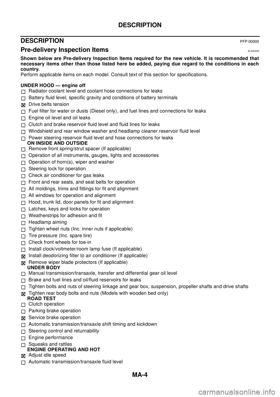
Pre-delivery Inspection ItemsELS000AK
Shown below are Pre-delivery Inspection Items required for the new vehicle. It is recommended that
necessary items other than those listed here be added, paying due regard to the conditions in each
country.
Perform applicable items on each model. Consult text of this section for specifications.
UNDER HOOD — engine off
Radiator coolant level and coolant hose connections for leaks
Battery fluid level, specific gravity and conditions of battery terminals
Drive belts tension
Fuel filter for water or dusts (Diesel only), and fuel lines and connections for leaks
Engine oil level and oil leaks
Clutch and brake reservoir fluid level and fluid lines for leaks
Windshield and rear window washer and headlamp cleaner reservoir fluid level
Power steering reservoir fluid level and hose connections for leaks
ON INSIDE AND OUTSIDE
Remove front spring/strut spacer (If applicable)
Operation of all instruments, gauges, lights and accessories
Operation of horn(s), wiper and washer
Steering lock for operation
Check air conditioner for gas leaks
Front and rear seats, and seat belts for operation
All moldings, trims and fittings for fit and alignment
All windows for operation and alignment
Hood, trunk lid, door panels for fit and alignment
Latches, keys and locks for operation
Weatherstrips for adhesion and fit
Headlamp aiming
Tighten wheel nuts (Inc. inner nuts if applicable)
Tire pressure (Inc. spare tire)
Check front wheels for toe-in
Install clock/voltmeter/room lamp fuse (If applicable)
Install deodorizing filter to air conditioner (If applicable)
Remove wiper blade protectors (If applicable)
UNDER BODY
Manual transmission/transaxle, transfer and differential gear oil level
Brake and fuel lines and oil/fluid reservoirs for leaks
Tighten bolts and nuts of steering linkage and gear box, suspension, propeller shafts and drive shafts
Tighten rear body bolts and nuts (Models with wooden bed only)
ROAD TEST
Clutch operation
Parking brake operation
Service brake operation
Automatic transmission/transaxle shift timing and kickdown
Steering control and returnability
Engine performance
Squeaks and rattles
ENGINE OPERATING AND HOT
Adjust idle speed
Automatic transmission/transaxle fluid level
Page 2498 of 3066
MA-6
GENERAL MAINTENANCE
GENERAL MAINTENANCE
PFP:00000
General MaintenanceELS000AL
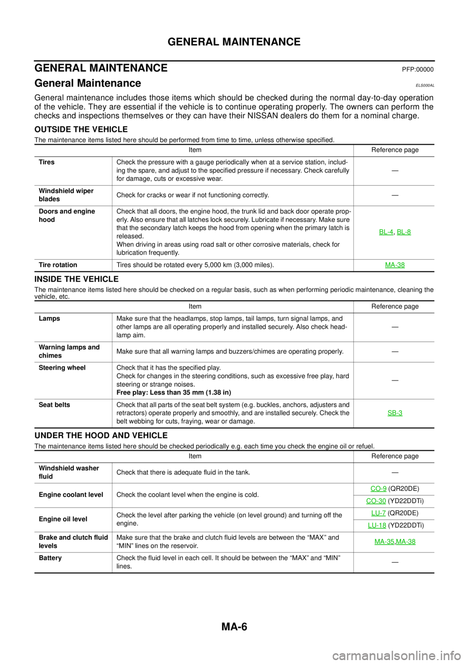
General maintenance includes those items which should be checked during the normal day-to-day operation
of the vehicle. They are essential if the vehicle is to continue operating properly. The owners can perform the
checks and inspections themselves or they can have their NISSAN dealers do them for a nominal charge.
OUTSIDE THE VEHICLE
The maintenance items listed here should be performed from time to time, unless otherwise specified.
INSIDE THE VEHICLE
The maintenance items listed here should be checked on a regular basis, such as when performing periodic maintenance, cleaning the
vehicle, etc.
UNDER THE HOOD AND VEHICLE
The maintenance items listed here should be checked periodically e.g. each time you check the engine oil or refuel.Item Reference page
TiresCheck the pressure with a gauge periodically when at a service station, includ-
ing the spare, and adjust to the specified pressure if necessary. Check carefully
for damage, cuts or excessive wear.—
Windshield wiper
bladesCheck for cracks or wear if not functioning correctly. —
Doors and engine
hoodCheck that all doors, the engine hood, the trunk lid and back door operate prop-
erly. Also ensure that all latches lock securely. Lubricate if necessary. Make sure
that the secondary latch keeps the hood from opening when the primary latch is
released.
When driving in areas using road salt or other corrosive materials, check for
lubrication frequently.BL-4
,BL-8
Tire rotationTires should be rotated every 5,000 km (3,000 miles).MA-38
Item Reference page
LampsMake sure that the headlamps, stop lamps, tail lamps, turn signal lamps, and
other lamps are all operating properly and installed securely. Also check head-
lamp aim.—
Warning lamps and
chimesMake sure that all warning lamps and buzzers/chimes are operating properly. —
Steering wheelCheck that it has the specified play.
Check for changes in the steering conditions, such as excessive free play, hard
steering or strange noises.
Free play: Less than 35 mm (1.38 in)—
Seat beltsCheck that all parts of the seat belt system (e.g. buckles, anchors, adjusters and
retractors) operate properly and smoothly, and are installed securely. Check the
belt webbing for cuts, fraying, wear or damage.SB-3
Item Reference page
Windshield washer
fluidCheck that there is adequate fluid in the tank. —
Engine coolant levelCheck the coolant level when the engine is cold.CO-9
(QR20DE)
CO-30
(YD22DDTi)
Engine oil levelCheck the level after parking the vehicle (on level ground) and turning off the
engine.LU-7
(QR20DE)
LU-18
(YD22DDTi)
Brake and clutch fluid
levelsMake sure that the brake and clutch fluid levels are between the “MAX” and
“MIN” lines on the reservoir.MA-35
,MA-38
BatteryCheck the fluid level in each cell. It should be between the “MAX” and “MIN”
lines.—
Page 2509 of 3066
RECOMMENDED FLUIDS AND LUBRICANTS
MA-17
C
D
E
F
G
H
I
J
K
MA
B
MA
RECOMMENDED FLUIDS AND LUBRICANTSPFP:00000
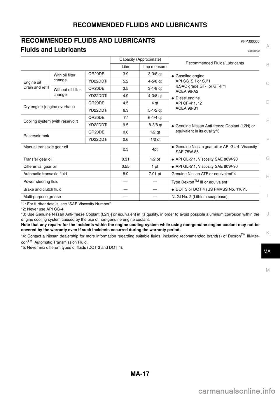
Fluids and LubricantsELS000C8
*1: For further details, see “SAE Viscosity Number”.
*2: Never use API CG-4.
*3: Use Genuine Nissan Anti-freeze Coolant (L2N)] or equivalent in its quality, in order to avoid possible aluminum corrosion within the
engine cooling system caused by the use of non-genuine engine coolant.
Note that any repairs for the incidents within the engine cooling system while using non-genuine engine coolant may not be
covered by the warranty even if such incidents occurred during the warranty period.
*4: Contact a Nissan dealership for more information regarding suitable fluids, including recommended brand(s) of Dexron
TMIII/Mer-
conTMAutomatic Transmission Fluid.
*5: Never mix different types of fluids (DOT 3 and DOT 4).Capacity (Approximate)
Recommended Fluids/Lubricants
Liter Imp measure
Engine oil
Drain and refillWith oil filter
changeQR20DE 3.9 3-3/8 qt
lGasoline engine
API SG, SH or SJ*1
ILSAC grade GF-I or GF-II*1
ACEA 96-A2
lDiesel engine
API CF-4*1, *2
ACEA 98-B1 YD22DDTi 5.2 4-5/8 qt
Without oil filter
changeQR20DE 3.5 3-1/8 qt
YD22DDTi 4.9 4-3/8 qt
Dry engine (engine overhaul)QR20DE 4.5 4 qt
YD22DDTi 6.3 5-1/2 qt
Cooling system (with reservoir)QR20DE 7.1 6-1/4 qt
lGenuine Nissan Anti-freeze Coolant (L2N) or
equivalent in its quality*3 YD22DDTi 9.5 8-3/8 qt
Reservoir tankQR20DE 0.6 1/2 qt
YD22DDTi 0.6 1/2 qt
Manual transaxle gear oil
2.3 4pt
lGenuine Nissan gear oil or API GL-4, Viscosity
SAE 75W-85
Transfer gear oil 0.31 1/2 pt
lAPI GL-5*1, Viscosity SAE 80W-90
Differential gear oil 0.55 1 pt
lAPI GL-5*1, Viscosity SAE 80W-90
Automatic transaxle fluid 8.0 7.01 pt Genuine Nissan ATF or equivalent*4
Power steering fluid — —
Ty p e D e x r o n
TMIII or equivalent
Brake and clutch fluid — —
lDOT 3 or DOT 4 (US FMVSS No. 116)*5
Multi-purpose grease — — NLGI No. 2 (Lithium soap base)
Page 2513 of 3066
ENGINE MAINTENANCE (QR20DE)
MA-21
C
D
E
F
G
H
I
J
K
MA
B
MA
2. Open drain plugs on cylinder block.
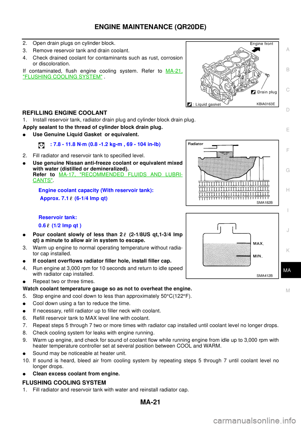
3. Remove reservoir tank and drain coolant.
4. Check drained coolant for contaminants such as rust, corrosion
or discoloration.
If contaminated, flush engine cooling system. Refer toMA-21,
"FLUSHING COOLING SYSTEM".
REFILLING ENGINE COOLANT
1. Install reservoir tank, radiator drain plug and cylinder block drain plug.
Apply sealant to the thread of cylinder block drain plug.
lUse Genuine Liquid Gasket or equivalent.
2. Fill radiator and reservoir tank to specified level.
lUse genuine Nissan anti-freeze coolant or equivalent mixed
with water (distilled or demineralized).
Refer toMA-17, "
RECOMMENDED FLUIDS AND LUBRI-
CANTS".
lPour coolant slowly of less than 2 (2-1/8US qt,1-3/4 lmp
qt) a minute to allow air in system to escape.
3. Warm up engine to normal operating temperature without radia-
tor cap installed.
lIf coolant overflows radiator filler hole, install filler cap.
4. Run engine at 3,000 rpm for 10 seconds and return to idle speed
with radiator cap installed.
lRepeat two or three times.
Watch coolant temperature gauge so as not to overheat the engine.
5. Stop engine and cool down to less than approximately 50°C(122°F).
lCool down using a fan to reduce the time.
lIf necessary, refill radiator up to filler neck with coolant.
6. Refill reservoir tank to MAX level line with coolant.
7. Repeat steps 5 through 7 two or more times with radiator cap installed until coolant level no longer drops.
8. Check cooling system for leaks with engine running.
9. Warm up engine, and check for sound of coolant flow while running engine from idle up to 3,000 rpm with
heater temperature controller set at several position between COOL and WARM.
lSound may be noticeable at heater unit.
10. If sound is heard, bleed air from cooling system by repeating steps 5 through 7 until coolant level no
longer drops.
lClean excess coolant from engine.
FLUSHING COOLING SYSTEM
1. Fill radiator and reservoir tank with water and reinstall radiator cap.
KBIA0163E
: 7.8 - 11.8 N·m (0.8 -1.2 kg-m , 69 - 104 in-lb)
Engine coolant capacity (With reservoir tank):
Approx. 7.1 (6-1/4 Imp qt)
SMA182B
Reservoir tank:
0.6 (1/2 lmp qt )
SMA412B
Page 2519 of 3066
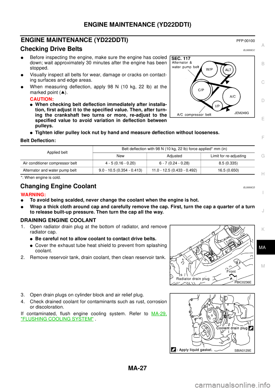
ENGINE MAINTENANCE (YD22DDTI)
MA-27
C
D
E
F
G
H
I
J
K
MA
B
MA
ENGINE MAINTENANCE (YD22DDTI)PFP:00100
Checking Drive BeltsEL S00 0C C
lBefore inspecting the engine, make sure the engine has cooled
down; wait approximately 30 minutes after the engine has been
stopped.
lVisually inspect all belts for wear, damage or cracks on contact-
ing surfaces and edge areas.
lWhen measuring deflection, apply 98 N (10 kg, 22 lb) at the
marked point ( ).
CAUTION:
lWhen checking belt deflection immediately after installa-
tion, first adjust it to the specified value. Then, after turn-
ing the crankshaft two turns or more, re-adjust to the
specified value to avoid variation in deflection between
pulleys.
lTighten idler pulley lock nut by hand and measure deflection without looseness.
Belt Deflection:
*: When engine is cold.
Changing Engine CoolantEL S00 0C D
WA RN ING:
lTo avoid being scalded, never change the coolant when the engine is hot.
lWrap a thick cloth around cap and carefully remove the cap. First, turn the cap a quarter of a turn
to release built-up pressure. Then turn the cap all the way.
DRAINING ENGINE COOLANT
1. Open radiator drain plug at the bottom of radiator, and remove
radiator cap.
lBe careful not to allow coolant to contact drive belts.
lCover the exhaust tube heat shield to prevent from splashing
coolant.
2. Remove reservoir tank, drain coolant, then clean reservoir tank.
3. Open drain plugs on cylinder block and air relief plug.
4. Check drained coolant for contaminants such as rust, corrosion
or discoloration.
If contaminated, flush engine cooling system. Refer toMA-29,
"FLUSHING COOLING SYSTEM".
JEM249G
Applied beltBelt deflection with 98 N (10 kg, 22 lb) force applied* mm (in)
New Adjusted Limit for re-adjusting
Air conditioner compressor belt 4 - 5 (0.16 - 0.20) 6 - 7 (0.24 - 0.28) 8.5 (0.335)
Alternator and water pump belt 9.0 - 10.5 (0.354 - 0.413) 11.0 - 12.5 (0.433 - 0.492) 16.5 (0.650)
PBIC0236E
SBIA0129E