fuel pump NISSAN X-TRAIL 2003 Electronic Repair Manual
[x] Cancel search | Manufacturer: NISSAN, Model Year: 2003, Model line: X-TRAIL, Model: NISSAN X-TRAIL 2003Pages: 3066, PDF Size: 51.47 MB
Page 1072 of 3066
DI-18
COMBINATION METERS (LHD MODELS)
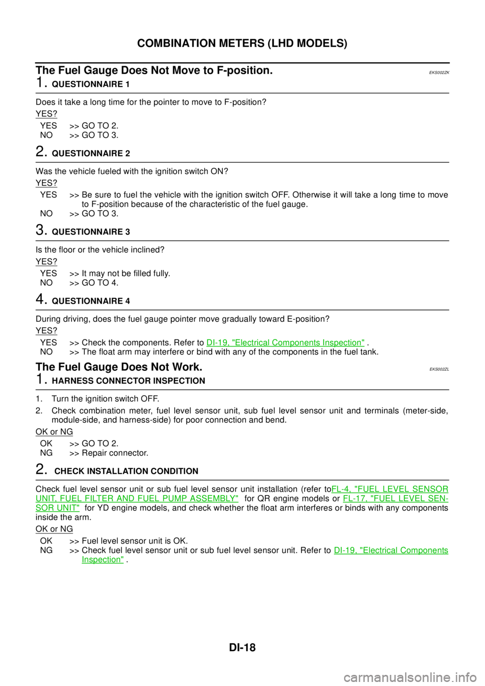
The Fuel Gauge Does Not Move to F-position.
EKS002ZK
1.QUESTIONNAIRE 1
Does it take a long time for the pointer to move to F-position?
YES?
YES >> GO TO 2.
NO >> GO TO 3.
2.QUESTIONNAIRE 2
Was the vehicle fueled with the ignition switch ON?
YES?
YES >> Be sure to fuel the vehicle with the ignition switch OFF. Otherwise it will take a long time to move
to F-position because of the characteristic of the fuel gauge.
NO >> GO TO 3.
3.QUESTIONNAIRE 3
Is the floor or the vehicle inclined?
YES?
YES >> It may not be filled fully.
NO >> GO TO 4.
4.QUESTIONNAIRE 4
During driving, does the fuel gauge pointer move gradually toward E-position?
YES?
YES >> Check the components. Refer toDI-19, "Electrical Components Inspection".
NO >> The float arm may interfere or bind with any of the components in the fuel tank.
The Fuel Gauge Does Not Work.EKS002ZL
1.HARNESS CONNECTOR INSPECTION
1. Turn the ignition switch OFF.
2. Check combination meter, fuel level sensor unit, sub fuel level sensor unit and terminals (meter-side,
module-side, and harness-side) for poor connection and bend.
OK or NG
OK >> GO TO 2.
NG >> Repair connector.
2.CHECK INSTALLATION CONDITION
Check fuel level sensor unit or sub fuel level sensor unit installation (refer toFL-4, "
FUEL LEVEL SENSOR
UNIT, FUEL FILTER AND FUEL PUMP ASSEMBLY"for QR engine models orFL-17, "FUEL LEVEL SEN-
SOR UNIT"for YD engine models, and check whether the float arm interferes or binds with any components
inside the arm.
OK or NG
OK >> Fuel level sensor unit is OK.
NG >> Check fuel level sensor unit or sub fuel level sensor unit. Refer toDI-19, "
Electrical Components
Inspection".
Page 1073 of 3066
COMBINATION METERS (LHD MODELS)
DI-19
C
D
E
F
G
H
I
J
L
MA
B
DI
Low Fuel Warning Lamp Illuminate or Not IlluminateEKS002ZM
1.DIAGNOSIS MODE INSPECTION
Preform combination meter diagnosis mode. Refer toDI-10, "
Meter/Gauge Operation and Odo/Trip Meter
Segment Check in Diagnosis Mode".
OK or NG
OK >> Check fuel level sensor unit or sub fuel level sensor unit. Refer toDI-19, "Electrical Components
Inspection".
NG >> Replace combination meter.
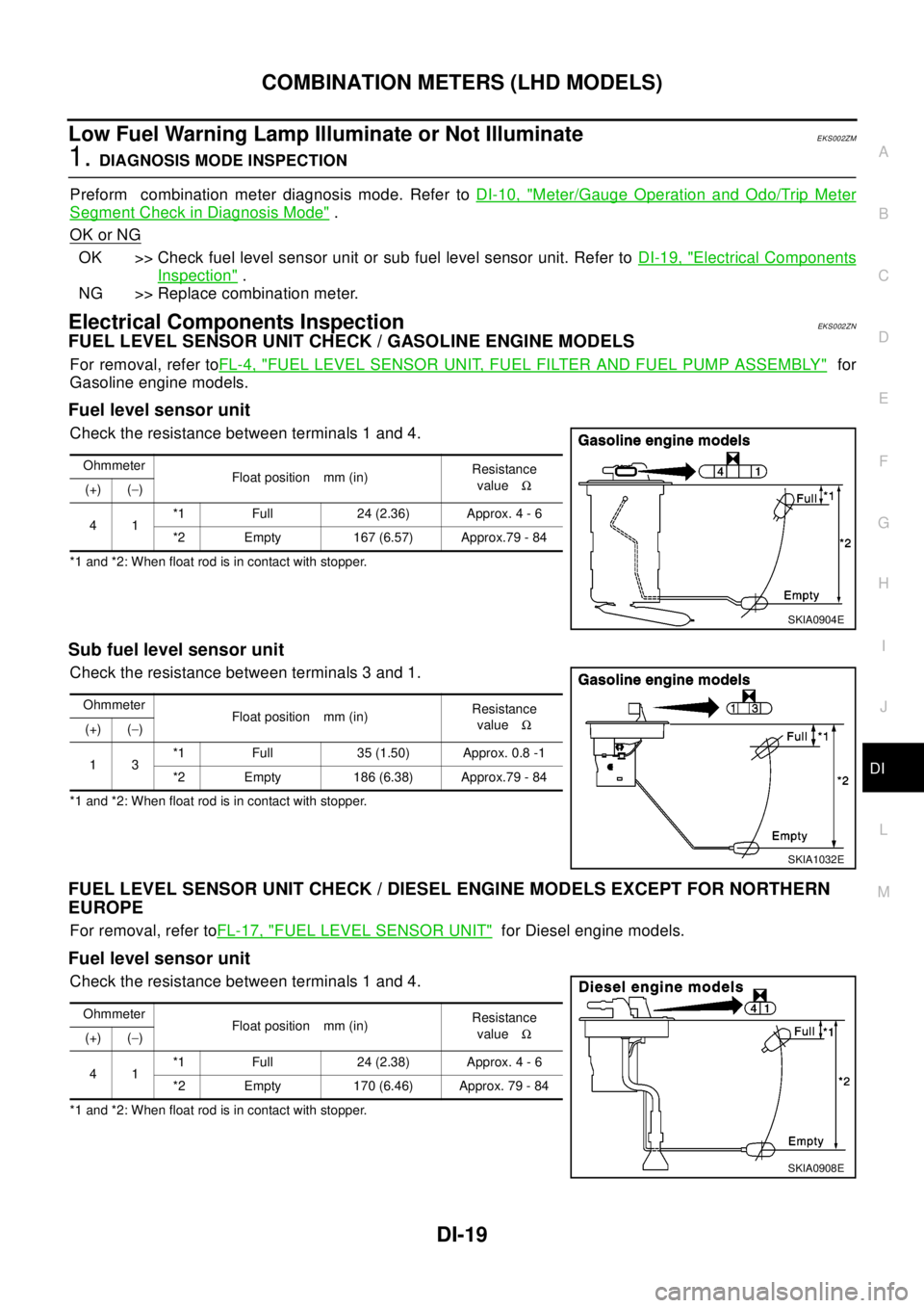
Electrical Components InspectionEKS002ZN
FUEL LEVEL SENSOR UNIT CHECK / GASOLINE ENGINE MODELS
For removal, refer toFL-4, "FUEL LEVEL SENSOR UNIT, FUEL FILTER AND FUEL PUMP ASSEMBLY"for
Gasoline engine models.
Fuel level sensor unit
Check the resistance between terminals 1 and 4.
*1 and *2: When float rod is in contact with stopper.
Sub fuel level sensor unit
Check the resistance between terminals 3 and 1.
*1 and *2: When float rod is in contact with stopper.
FUEL LEVEL SENSOR UNIT CHECK / DIESEL ENGINE MODELS EXCEPT FOR NORTHERN
EUROPE
For removal, refer toFL-17, "FUEL LEVEL SENSOR UNIT"for Diesel engine models.
Fuel level sensor unit
Check the resistance between terminals 1 and 4.
*1 and *2: When float rod is in contact with stopper.Ohmmeter
Float position mm (in)Resistance
valueW
(+) (-)
41*1 Full 24 (2.36) Approx. 4 - 6
*2 Empty 167 (6.57) Approx.79 - 84
SKIA0904E
Ohmmeter
Float position mm (in)Resistance
valueW
(+) (-)
13*1 Full 35 (1.50) Approx. 0.8 -1
*2 Empty 186 (6.38) Approx.79 - 84
SKIA1032E
Ohmmeter
Float position mm (in)Resistance
valueW
(+) (-)
41*1 Full 24 (2.38) Approx. 4 - 6
*2 Empty 170 (6.46) Approx. 79 - 84
SKIA0908E
Page 1090 of 3066
DI-36
COMBINATION METERS (RHD MODELS)
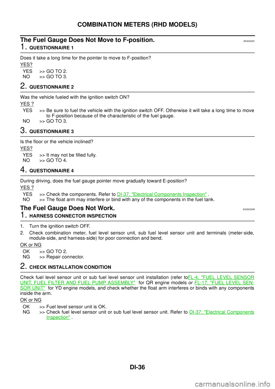
The Fuel Gauge Does Not Move to F-position.
EKS0030V
1.QUESTIONNAIRE 1
Does it take a long time for the pointer to move to F-position?
YES?
YES >> GO TO 2.
NO >> GO TO 3.
2.QUESTIONNAIRE 2
Was the vehicle fueled with the ignition switch ON?
YES ?
YES >> Be sure to fuel the vehicle with the ignition switch OFF. Otherwise it will take a long time to move
to F-position because of the characteristic of the fuel gauge.
NO >> GO TO 3.
3.QUESTIONNAIRE 3
Is the floor or the vehicle inclined?
YES?
YES >> It may not be filled fully.
NO >> GO TO 4.
4.QUESTIONNAIRE 4
During driving, does the fuel gauge pointer move gradually toward E-position?
YES ?
YES >> Check the components. Refer toDI-37, "Electrical Components Inspection".
NO >> The float arm may interfere or bind with any of the components in the fuel tank.
The Fuel Gauge Does Not Work.EKS0030W
1.HARNESS CONNECTOR INSPECTION
1. Turn the ignition switch OFF.
2. Check combination meter, fuel level sensor unit, sub fuel level sensor unit and terminals (meter-side,
module-side, and harness-side) for poor connection and bend.
OK or NG
OK >> GO TO 2.
NG >> Repair connector.
2.CHECK INSTALLATION CONDITION
Check fuel level sensor unit or sub fuel level sensor unit installation (refer toFL-4, "
FUEL LEVEL SENSOR
UNIT, FUEL FILTER AND FUEL PUMP ASSEMBLY"for QR engine models orFL-17, "FUEL LEVEL SEN-
SOR UNIT"for YD engine models, and check whether the float arm interferes or binds with any components
inside the arm.
OK or NG
OK >> Fuel level sensor unit is OK.
NG >> Check fuel level sensor unit or sub fuel level sensor unit. Refer toDI-37, "
Electrical Components
Inspection".
Page 1091 of 3066
COMBINATION METERS (RHD MODELS)
DI-37
C
D
E
F
G
H
I
J
L
MA
B
DI
Low Fuel Warning Lamp Illuminate or Not IlluminateEKS0030X
1.DIAGNOSIS MODE INSPECTION
Preform combination meter diagnosis mode. Refer toDI-28, "
Meter/Gauge Operation and Odo/Trip Meter
Segment Check in Diagnosis Mode".
OK or NG
OK >> Check fuel level sensor unit or sub fuel level sensor unit. Refer toDI-37, "Electrical Components
Inspection".
NG >> Replace combination meter.
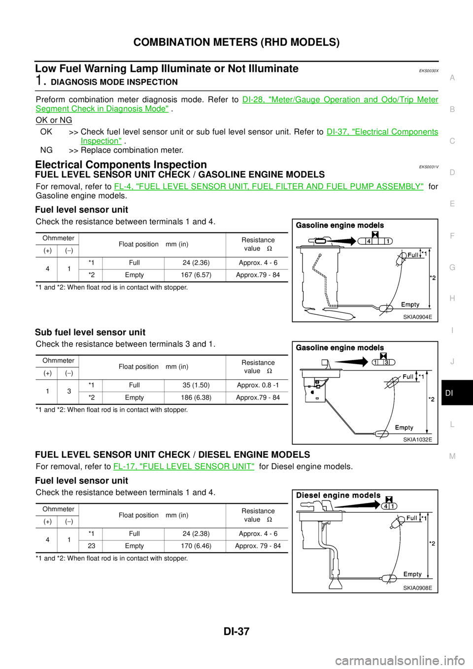
Electrical Components InspectionEKS0031V
FUEL LEVEL SENSOR UNIT CHECK / GASOLINE ENGINE MODELS
For removal, refer toFL-4, "FUEL LEVEL SENSOR UNIT, FUEL FILTER AND FUEL PUMP ASSEMBLY"for
Gasoline engine models.
Fuel level sensor unit
Check the resistance between terminals 1 and 4.
*1 and *2: When float rod is in contact with stopper.
Sub fuel level sensor unit
Check the resistance between terminals 3 and 1.
*1 and *2: When float rod is in contact with stopper.
FUEL LEVEL SENSOR UNIT CHECK / DIESEL ENGINE MODELS
For removal, refer toFL-17, "FUEL LEVEL SENSOR UNIT"for Diesel engine models.
Fuel level sensor unit
Check the resistance between terminals 1 and 4.
*1 and *2: When float rod is in contact with stopper.Ohmmeter
Float position mm (in)Resistance
valueW
(+) (-)
41*1 Full 24 (2.36) Approx. 4 - 6
*2 Empty 167 (6.57) Approx.79 - 84
SKIA0904E
Ohmmeter
Float position mm (in)Resistance
valueW
(+) (-)
13*1 Full 35 (1.50) Approx. 0.8 -1
*2 Empty 186 (6.38) Approx.79 - 84
SKIA1032E
Ohmmeter
Float position mm (in)Resistance
valueW
(+) (-)
41*1 Full 24 (2.38) Approx. 4 - 6
23 Empty 170 (6.46) Approx. 79 - 84
SKIA0908E
Page 1119 of 3066
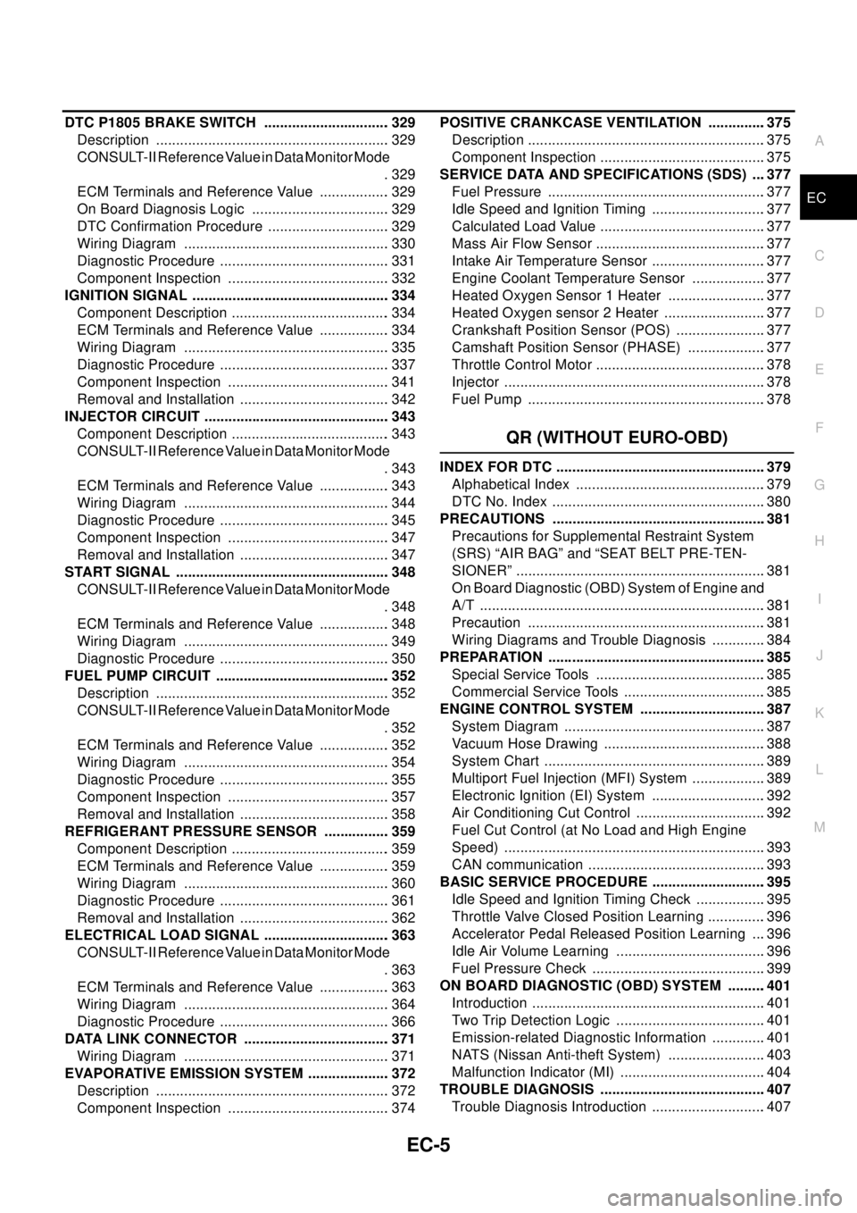
EC-5
C
D
E
F
G
H
I
J
K
L
M
ECA DTC P1805 BRAKE SWITCH ................................ 329
Description ........................................................... 329
CONSULT-II Reference Value in Data Monitor Mode
. 329
ECM Terminals and Reference Value .................. 329
On Board Diagnosis Logic ................................... 329
DTC Confirmation Procedure ............................... 329
Wiring Diagram .................................................... 330
Diagnostic Procedure ........................................... 331
Component Inspection ......................................... 332
IGNITION SIGNAL .................................................. 334
Component Description ........................................ 334
ECM Terminals and Reference Value .................. 334
Wiring Diagram .................................................... 335
Diagnostic Procedure ........................................... 337
Component Inspection ......................................... 341
Removal and Installation ...................................... 342
INJECTOR CIRCUIT ............................................... 343
Component Description ........................................ 343
CONSULT-II Reference Value in Data Monitor Mode
. 343
ECM Terminals and Reference Value .................. 343
Wiring Diagram .................................................... 344
Diagnostic Procedure ........................................... 345
Component Inspection ......................................... 347
Removal and Installation ...................................... 347
START SIGNAL ...................................................... 348
CONSULT-II Reference Value in Data Monitor Mode
. 348
ECM Terminals and Reference Value .................. 348
Wiring Diagram .................................................... 349
Diagnostic Procedure ........................................... 350
FUEL PUMP CIRCUIT ............................................ 352
Description ........................................................... 352
CONSULT-II Reference Value in Data Monitor Mode
. 352
ECM Terminals and Reference Value .................. 352
Wiring Diagram .................................................... 354
Diagnostic Procedure ........................................... 355
Component Inspection ......................................... 357
Removal and Installation ...................................... 358
REFRIGERANT PRESSURE SENSOR ................. 359
Component Description ........................................ 359
ECM Terminals and Reference Value .................. 359
Wiring Diagram .................................................... 360
Diagnostic Procedure ........................................... 361
Removal and Installation ...................................... 362
ELECTRICAL LOAD SIGNAL ................................ 363
CONSULT-II Reference Value in Data Monitor Mode
. 363
ECM Terminals and Reference Value .................. 363
Wiring Diagram .................................................... 364
Diagnostic Procedure ........................................... 366
DATA LINK CONNECTOR ..................................... 371
Wiring Diagram .................................................... 371
EVAPORATIVE EMISSION SYSTEM ..................... 372
Description ........................................................... 372
Component Inspection ......................................... 374POSITIVE CRANKCASE VENTILATION ...............375
Description ............................................................375
Component Inspection ..........................................375
SERVICE DATA AND SPECIFICATIONS (SDS) ....377
Fuel Pressure .......................................................377
Idle Speed and Ignition Timing .............................377
Calculated Load Value ..........................................377
Mass Air Flow Sensor ...........................................377
Intake Air Temperature Sensor .............................377
Engine Coolant Temperature Sensor ...................377
Heated Oxygen Sensor 1 Heater .........................377
Heated Oxygen sensor 2 Heater ..........................377
Crankshaft Position Sensor (POS) .......................377
Camshaft Position Sensor (PHASE) ....................377
Throttle Control Motor ...........................................378
Injector ..................................................................378
Fuel Pump ............................................................378
QR (WITHOUT EURO-OBD)
INDEX FOR DTC .....................................................379
Alphabetical Index ................................................379
DTC No. Index ......................................................380
PRECAUTIONS ......................................................381
Precautions for Supplemental Restraint System
(SRS) “AIR BAG” and “SEAT BELT PRE-TEN-
SIONER” ...............................................................381
On Board Diagnostic (OBD) System of Engine and
A/T ........................................................................381
Precaution ............................................................381
Wiring Diagrams and Trouble Diagnosis ..............384
PREPARATION .......................................................385
Special Service Tools ...........................................385
Commercial Service Tools ....................................385
ENGINE CONTROL SYSTEM ................................387
System Diagram ...................................................387
Vacuum Hose Drawing .........................................388
System Chart ........................................................389
Multiport Fuel Injection (MFI) System ...................389
Electronic Ignition (EI) System .............................392
Air Conditioning Cut Control .................................392
Fuel Cut Control (at No Load and High Engine
Speed) ..................................................................393
CAN communication .............................................393
BASIC SERVICE PROCEDURE .............................395
Idle Speed and Ignition Timing Check ..................395
Throttle Valve Closed Position Learning ...............396
Accelerator Pedal Released Position Learning ....396
Idle Air Volume Learning ......................................396
Fuel Pressure Check ............................................399
ON BOARD DIAGNOSTIC (OBD) SYSTEM ..........401
Introduction ...........................................................401
Two Trip Detection Logic ......................................401
Emission-related Diagnostic Information ..............401
NATS (Nissan Anti-theft System) .........................403
Malfunction Indicator (MI) .....................................404
TROUBLE DIAGNOSIS ..........................................407
Trouble Diagnosis Introduction .............................407
Page 1122 of 3066

EC-8
Component Inspection ..........................................584
Removal and Installation ......................................586
HO2S2 .....................................................................587
Component Description ........................................587
CONSULT-II Reference Value in Data Monitor Mode
.587
ECM Terminals and Reference Value ...................587
Wiring Diagram .....................................................588
Diagnostic Procedure ...........................................589
Component Inspection ..........................................590
Removal and Installation ......................................591
IGNITION SIGNAL ..................................................592
Component Description ........................................592
ECM Terminals and Reference Value ...................592
Wiring Diagram .....................................................593
Diagnostic Procedure ...........................................595
Component Inspection ..........................................599
Removal and Installation ......................................600
EVAP CANISTER PURGE VOLUME CONTROL
SOLENOID VALVE .................................................601
Description ............................................................601
CONSULT-II Reference Value in Data Monitor Mode
.601
ECM Terminals and Reference Value ...................601
Wiring Diagram .....................................................603
Diagnostic Procedure ...........................................604
Component Inspection ..........................................607
Removal and Installation ......................................607
IVT CONTROL SOLENOID VALVE ........................608
Description ............................................................608
CONSULT-II Reference Value in Data Monitor Mode
.608
ECM Terminals and Reference Value ...................609
Wiring Diagram .....................................................610
Diagnostic Procedure ...........................................611
Component Inspection ..........................................613
Removal and Installation ......................................613
PNP SWITCH ..........................................................614
Component Description ........................................614
CONSULT-II Reference Value in Data Monitor Mode
.614
ECM Terminals and Reference Value ...................614
Wiring Diagram .....................................................615
Diagnostic Procedure ...........................................616
INJECTOR CIRCUIT ...............................................618
Component Description ........................................618
CONSULT-II Reference Value in Data Monitor Mode
.618
ECM Terminals and Reference Value ...................618
Wiring Diagram .....................................................619
Diagnostic Procedure ...........................................620
Component Inspection ..........................................622
Removal and Installation ......................................622
START SIGNAL ......................................................623
CONSULT-II Reference Value in Data Monitor Mode
.623
ECM Terminals and Reference Value ...................623Wiring Diagram ..................................................... 624
Diagnostic Procedure ............................................ 625
FUEL PUMP CIRCUIT ............................................. 627
Description ............................................................ 627
CONSULT-II Reference Value in Data Monitor Mode
. 627
ECM Terminals and Reference Value ................... 627
Wiring Diagram ..................................................... 629
Diagnostic Procedure ............................................ 630
Component Inspection .......................................... 632
Removal and Installation ....................................... 633
REFRIGERANT PRESSURE SENSOR .................. 634
Component Description ........................................ 634
ECM Terminals and Reference Value ................... 634
Wiring Diagram ..................................................... 635
Diagnostic Procedure ............................................ 636
Removal and Installation ....................................... 637
ELECTRICAL LOAD SIGNAL ................................ 638
CONSULT-II Reference Value in Data Monitor Mode
. 638
ECM Terminals and Reference Value ................... 638
Wiring Diagram ..................................................... 639
Diagnostic Procedure ............................................ 641
DATA LINK CONNECTOR ...................................... 646
Wiring Diagram ..................................................... 646
EVAPORATIVE EMISSION SYSTEM ..................... 647
Description ............................................................ 647
Component Inspection .......................................... 649
POSITIVE CRANKCASE VENTILATION ................ 650
Description ............................................................ 650
Component Inspection .......................................... 650
SERVICE DATA AND SPECIFICATIONS (SDS) .... 652
Fuel Pressure ........................................................ 652
Idle Speed and Ignition Timing .............................. 652
Calculated Load Value .......................................... 652
Mass Air Flow Sensor ........................................... 652
Intake Air Temperature Sensor ............................. 652
Engine Coolant Temperature Sensor .................... 652
Heated Oxygen Sensor 1 Heater .......................... 652
Heated Oxygen sensor 2 Heater .......................... 652
Crankshaft Position Sensor (POS) ....................... 652
Camshaft Position Sensor (PHASE) ..................... 652
Throttle Control Motor ........................................... 653
Injector .................................................................. 653
Fuel Pump ............................................................. 653
YD
INDEX FOR DTC ..................................................... 654
Alphabetical Index ................................................. 654
DTC No. Index ...................................................... 654
PRECAUTIONS ....................................................... 656
Precautions for Supplemental Restraint System
(SRS) “AIR BAG” and “SEAT BELT PRE-TEN-
SIONER” ............................................................... 656
Precautions ........................................................... 656
Wiring Diagrams and Trouble Diagnosis ............... 658
Page 1132 of 3066
![NISSAN X-TRAIL 2003 Electronic Repair Manual EC-18
[QR (WITH EURO-OBD)]
PRECAUTIONS
lAfter performing each TROUBLE DIAGNOSIS, perform
“DTC Confirmation Procedure” or “Overall Function
Check”.
The DTC should not be displayed in the “DTC NISSAN X-TRAIL 2003 Electronic Repair Manual EC-18
[QR (WITH EURO-OBD)]
PRECAUTIONS
lAfter performing each TROUBLE DIAGNOSIS, perform
“DTC Confirmation Procedure” or “Overall Function
Check”.
The DTC should not be displayed in the “DTC](/img/5/57402/w960_57402-1131.png)
EC-18
[QR (WITH EURO-OBD)]
PRECAUTIONS
lAfter performing each TROUBLE DIAGNOSIS, perform
“DTC Confirmation Procedure” or “Overall Function
Check”.
The DTC should not be displayed in the “DTC Confirmation
Procedure” if the repair is completed. The “Overall Func-
tion Check” should be a good result if the repair is com-
pleted.
lWhen measuring ECM signals with a circuit tester, never
allow the two tester probes to contact.
Accidental contact of probes will cause a short circuit and
damage the ECM power transistor.
lDo not use ECM ground terminals when measuring input/
output voltage. Doing so may result in damage to the ECM's
transistor. Use a ground other than ECM terminals, such as
the ground.
lDo not operate fuel pump when there is no fuel in lines.
lTighten fuel hose clamps to the specified torque.
SAT652J
SEF348N
PBIB0513E
Page 1138 of 3066
![NISSAN X-TRAIL 2003 Electronic Repair Manual EC-24
[QR (WITH EURO-OBD)]
ENGINE CONTROL SYSTEM
System Chart
EBS00B0Q
*1: This sensor is not used to control the engine system under normal conditions.
*2: These signals are sent to the ECM through C NISSAN X-TRAIL 2003 Electronic Repair Manual EC-24
[QR (WITH EURO-OBD)]
ENGINE CONTROL SYSTEM
System Chart
EBS00B0Q
*1: This sensor is not used to control the engine system under normal conditions.
*2: These signals are sent to the ECM through C](/img/5/57402/w960_57402-1137.png)
EC-24
[QR (WITH EURO-OBD)]
ENGINE CONTROL SYSTEM
System Chart
EBS00B0Q
*1: This sensor is not used to control the engine system under normal conditions.
*2: These signals are sent to the ECM through CAN communication line.
Multiport Fuel Injection (MFI) SystemEBS00B0R
INPUT/OUTPUT SIGNAL CHART
*1: Under normal conditions, this sensor is not for engine control operation.
*2: This signal is sent to the ECM through CAN communication line.Input (Sensor) ECM Function Output (Actuator)
lCamshaft position sensor (PHASE)
lCrankshaft position sensor (POS)
lMass air flow sensor
lEngine coolant temperature sensor
lHeated oxygen sensor 1
lThrottle position sensor
lAccelerator pedal position sensor
lPark/neutral position (PNP) switch
lIntake air temperature sensor
lPower steering pressure sensor
lIgnition switch
lBattery voltage
lKnock sensor
lRefrigerant pressure sensor
lHeated oxygen sensor 2 *1
lTCM (Transmission control module) *2
lESP/TCS/ABS control unit *2
lWheel sensor
lAir conditioner switch
lElectrical loadFuel injection & mixture ratio control Fuel injectors
Electronic ignition system Power transistors
Fuel pump control Fuel pump relay
On board diagnostic system MI (On the instrument panel)
Heated oxygen sensor 1 heater control Heated oxygen sensor 1 heater
Heated oxygen sensor 2 heater control Heated oxygen sensor 2 heater
EVAP canister purge flow controlEVAP canister purge volume control
solenoid valve
Air conditioning cut control Air conditioner relay
Cooling fan control Cooling fan relays
Sensor Input Signal to ECMECM func-
tionActuator
Crankshaft position sensor (POS)
Engine speed
Piston position
Fuel injec-
tion & mix-
ture ratio
controlFuel injectors Camshaft position sensor (PHASE)
Mass air flow sensor Amount of intake air
Engine coolant temperature sensor Engine coolant temperature
Heated oxygen sensor 1 Density of oxygen in exhaust gas
Throttle position sensor Throttle position
Accelerator pedal position sensor Accelerator pedal position
Park/neutral position (PNP) switch Gear position
Ignition switch Start signal
Knock sensor Engine knocking condition
Battery Battery voltage
Power steering pressure sensor Power steering operation
Heated oxygen sensor 2 *1 Density of oxygen in exhaust gas
ESP/TCS/ABS control unit *2 ESP/TCS operation command
Wheel sensor Vehicle speed
Air conditioner switch Air conditioner operation
Page 1148 of 3066
![NISSAN X-TRAIL 2003 Electronic Repair Manual EC-34
[QR (WITH EURO-OBD)]
BASIC SERVICE PROCEDURE
DIAGNOSTIC PROCEDURE
If idle air volume learning cannot be performed successfully, proceed as follows:
1.Check that throttle valve is fully closed.
2 NISSAN X-TRAIL 2003 Electronic Repair Manual EC-34
[QR (WITH EURO-OBD)]
BASIC SERVICE PROCEDURE
DIAGNOSTIC PROCEDURE
If idle air volume learning cannot be performed successfully, proceed as follows:
1.Check that throttle valve is fully closed.
2](/img/5/57402/w960_57402-1147.png)
EC-34
[QR (WITH EURO-OBD)]
BASIC SERVICE PROCEDURE
DIAGNOSTIC PROCEDURE
If idle air volume learning cannot be performed successfully, proceed as follows:
1.Check that throttle valve is fully closed.
2.Check PCV valve operation.
3.Check that downstream of throttle valve is free from air leakage.
4.When the above three items check out OK, engine component parts and their installation condi-
tion are questionable. Check and eliminate the cause of the problem.
It is useful to performEC-103, "
TROUBLE DIAGNOSIS - SPECIFICATION VALUE".
5.If any of the following conditions occur after the engine has started, eliminate the cause of the
problem and perform “Idle air volume learning” all over again:
–Engine stalls.
–Erroneous idle.
Fuel Pressure CheckEBS00B0Z
FUEL PRESSURE RELEASE
Before disconnecting fuel line, release fuel pressure from fuel line to eliminate danger.
NOTE:
Prepare pans or saucers under the disconnected fuel line because the fuel may spill out. The fuel pres-
sure cannot be completely released because QR engine models do not have fuel return system.
With CONSULT-II
1. Turn ignition switch “ON”.
2. Perform “FUEL PRESSURE RELEASE” in “WORK SUPPORT”
mode with CONSULT-II.
3. Start engine.
4. After engine stalls, crank it two or three times to release all fuel
pressure.
5. Turn ignition switch “OFF”.
Without CONSULT-II
1. Remove fuel pump fuse located in fuse box.
2. Start engine.
3. After engine stalls, crank it two or three times to release all fuel
pressure.
4. Turn ignition switch “OFF”.
5. Reinstall fuel pump fuse after servicing fuel system.
FUEL PRESSURE CHECK
CAUTION:
lThe fuel hose connection method used when taking fuel pressure check must not be used for
other purposes.
lTake care for not to scratch and not to put debris around connection area when servicing, so that
the quick connector keeps sealability with O-rings inside.
1. Release fuel pressure to zero. Refer toEC-34, "
FUEL PRESSURE RELEASE".
2. Prepare fuel hose for fuel pressure check, and connect fuel pressure gauge.
lUse suitable fuel hose for fuel pressure check (genuine NISSAN fuel hose without quick connector).
SEF214Y
PBIB0508E
Page 1149 of 3066
![NISSAN X-TRAIL 2003 Electronic Repair Manual BASIC SERVICE PROCEDURE
EC-35
[QR (WITH EURO-OBD)]
C
D
E
F
G
H
I
J
K
L
MA
EC
lTo avoid unnecessary force or tension to hose, use moderately long fuel hose for fuel pressure check.
lDo not use the fuel NISSAN X-TRAIL 2003 Electronic Repair Manual BASIC SERVICE PROCEDURE
EC-35
[QR (WITH EURO-OBD)]
C
D
E
F
G
H
I
J
K
L
MA
EC
lTo avoid unnecessary force or tension to hose, use moderately long fuel hose for fuel pressure check.
lDo not use the fuel](/img/5/57402/w960_57402-1148.png)
BASIC SERVICE PROCEDURE
EC-35
[QR (WITH EURO-OBD)]
C
D
E
F
G
H
I
J
K
L
MA
EC
lTo avoid unnecessary force or tension to hose, use moderately long fuel hose for fuel pressure check.
lDo not use the fuel hose for checking fuel pressure with damage or cracks on it.
lUse Pressure Gauge to check fuel pressure.
3. Remove fuel hose. Refer toEM-17, "
INTAKE MANIFOLD".
lDo not twist or kink fuel hose because it is plastic hose.
lDo not remove fuel hose from quick connector.
lKeep the original fuel hose to be free from intrusion of dust or foreign substances with a suitable cover.
4. Install the fuel pressure gauge as shown in the figure.
lWipe off oil or dirt from hose insertion part using cloth moist-
ened with gasoline.
lApply proper amount of gasoline between top of the fuel tube
and No.1 spool.
lInsert fuel hose for fuel pressure check until it touches the
No.1 spool on fuel tube.
lUse NISSAN genuine hose clamp (part number: 16439
N4710 or 16439 40U00).
lWhen reconnecting fuel line, always use new clamps.
lWhen reconnecting fuel hose, check the original fuel hose for
damage and abnormality.
lUse a torque driver to tighten clamps.
lInstall hose clamp to the position within 1 - 2 mm (0.04 - 0.08
in).
lMake sure that clamp screw does not contact adjacent parts.
5. After connecting fuel hose for fuel pressure check, pull the hose
with a force of approximately 98 N (10 kg, 22 lb) to confirm fuel
tube does not come off.
6. Turn ignition switch "ON", and check for fuel leakage.
7. Start engine and check for fuel leakage.
8. Read the indication of fuel pressure gauge.
lDo not perform fuel pressure check with system operating. Fuel pressure gauge may indicate false
readings.
lDuring fuel pressure check, confirm for fuel leakage from fuel connection every 3 minutes.
9. If result is unsatisfactory, go to next step.
10. Check the following.
lFuel hoses and fuel tubes for clogging
lFuel filter for clogging
lFuel pump
lFuel pressure regulator for clogging
If OK, replace fuel pressure regulator.
If NG, repair or replace.Tightening torque: 1 - 1.5 N·m (0.1 - 0.15 kg-m,
9-13in-lb)
At idling:
Approximately 350 kPa (3.5 bar, 3.7 kg/cm
2,51psi)
PBIB0669E
PBIB0670E