ad blue NISSAN X-TRAIL 2003 Electronic Repair Manual
[x] Cancel search | Manufacturer: NISSAN, Model Year: 2003, Model line: X-TRAIL, Model: NISSAN X-TRAIL 2003Pages: 3066, PDF Size: 51.47 MB
Page 14 of 3066

AT-8
PRECAUTIONS
lVehicle has TCC shudder and/or no TCC apply. Replace only after all hydraulic and electrical diagnoses
have been made. (Converter clutch material may be glazed.)
lConverter is contaminated with engine coolant containing antifreeze.
lInternal failure of stator roller clutch.
lHeavy clutch debris due to overheating (blue converter).
lSteel particles or clutch lining material found in fluid filter or on magnet when no internal parts in unit are
worn or damaged — indicates that lining material came from converter.
The torque converter should not be replaced if:
lThe fluid has an odor, is discolored, and there is no evidence of metal or clutch facing particles.
lThe threads in one or more of the converter bolt holes are damaged.
lTransaxle failure did not display evidence of damaged or worn internal parts, steel particles or clutch plate
lining material in unit and inside the fluid filter.
lVehicle has been exposed to high mileage (only). The exception may be where the torque converter
clutch dampener plate lining has seen excess wear by vehicles operated in heavy and/or constant traffic,
such as taxi, delivery or police use.
EURO-OBD SELF-DIAGNOSIS — EURO-OBD —
lA/T self-diagnosis is performed by the TCM in combination with the ECM. The results can be read through
the blinking pattern of the O/D OFF indicator lamp or the malfunction indicator lamp (MIL). Refer to the
table onAT-42, "
SELF-DIAGNOSTIC RESULT TEST MODE"for the indicator used to display each self-
diagnostic result.
lThe self-diagnostic results indicated by the MIL are automatically stored in both the ECM and TCM mem-
ories.
Always perform the procedure “HOW TO ERASE DTC” onAT-39, "
HOW TO ERASE DTC"to com-
plete the repair and avoid unnecessary blinking of the MIL.
lThe following self-diagnostic items can be detected using ECM self-diagnostic results mode* only when
the O/D OFF indicator lamp does not indicate any malfunctions.
–PNP switch
–A/T 1st, 2nd, 3rd, or 4th gear function
*: For details of EURO-OBD, refer toAT - 3 7 , "
ON BOARD DIAGNOSTIC SYSTEM DESCRIPTION".
lCertain systems and components, especially those related to EURO-OBD, may use a new style
slide-locking type harness connector.
For description and how to disconnect, refer toPG-70, "
HARNESS CONNECTOR".
Wiring Diagrams and Trouble DiagnosisECS004Q4
When you read wiring diagrams, refer to the following:
lGI-14, "How to Read Wiring Diagrams".
lPG-2, "POWER SUPPLY ROUTING".
When you perform trouble diagnosis, refer to the following:
lGI-11, "HOW TO FOLLOW TEST GROUPS IN TROUBLE DIAGNOSES".
l"", “HOW TO PERFORM EFFICIENT DIAGNOSIS FOR AN ELECTRICAL INCIDENT”
Page 588 of 3066

ATC-10
PRECAUTIONS
CHARGING CYLINDER
Using a charging cylinder is not recommended. Refrigerant may be vented into air from cylinder's top valve
when filling the cylinder with refrigerant. Also, the accuracy of the cylinder is generally less than that of an
electronic scale or of quality recycle/recharge equipment.
Precautions for Leak Detection DyeEJS000T7
lThe A/C system contains a fluorescent leak detection dye used for locating refrigerant leaks. An ultraviolet
(UV) lamp is required to illuminate the dye when inspecting for leaks.
lAlways wear fluorescence enhancing UV safety glasses to protect your eyes and enhance the visibility of
the fluorescent dye.
lThe fluorescent dye leak detector is not a replacement for an electronic refrigerant leak detector. The fluo-
rescent dye leak detector should be used in conjunction with an electronic refrigerant leak detector to (J-
41995) pin-point refrigerant leaks.
lFor your safety and your Customer's satisfaction, read and follow all manufacture's operating instructions
and precautions prior to performing the work.
lA compressor shaft seal should not be repaired because of dye seepage. The compressor shaft seal
should only be repaired after confirming the leak with an electronic refrigerant leak detector (J-41995).
lAlways remove any remaining dye from the leak area after repairs are complete to avoid a misdiagnosis
during a future service.
lDo not allow dye to come into contact with painted body panels or interior components. If dye is spilled,
clean immediately with the approved dye cleaner. Fluorescent dye left on a surface for an extended period
of time cannot be removed.
lDo not spray the fluorescent dye cleaning agent on hot surfaces (engine exhaust manifold, etc.).
lDo not use more than one refrigerant dye bottle (1/4 ounce / 7.4 cc) per A/C system.
lLeak detection dyes for R-134a and R12 A/C systems are different. Do not use R-134a leak detection dye
in R-12 A/C system or R-12 leak detector dye in R-134a A/C systems or A/C system damage may result.
lThe fluorescent properties of the dye will remain for over three (3) years unless a compressor failure
occurs.
IDENTIFICATION
NOTE:
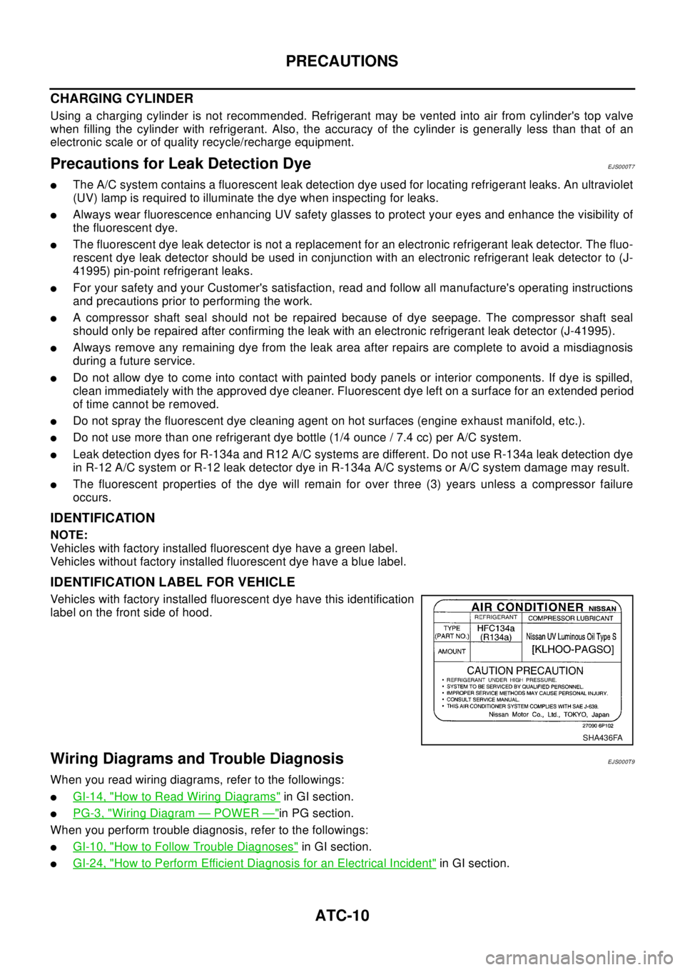
Vehicles with factory installed fluorescent dye have a green label.
Vehicles without factory installed fluorescent dye have a blue label.
IDENTIFICATION LABEL FOR VEHICLE
Vehicles with factory installed fluorescent dye have this identification
label on the front side of hood.
Wiring Diagrams and Trouble DiagnosisEJS000T9
When you read wiring diagrams, refer to the followings:
lGI-14, "How to Read Wiring Diagrams"in GI section.
lPG-3, "Wiring Diagram—POWER—"in PG section.
When you perform trouble diagnosis, refer to the followings:
lGI-10, "How to Follow Trouble Diagnoses"in GI section.
lGI-24, "How to Perform Efficient Diagnosis for an Electrical Incident"in GI section.
SHA436FA
Page 590 of 3066

ATC-12
PREPARATION
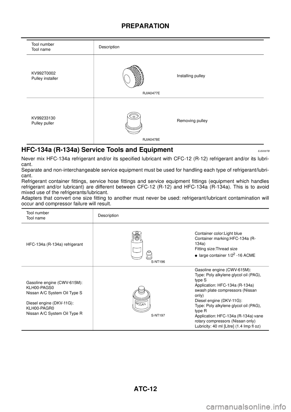
HFC-134a (R-134a) Service Tools and Equipment
EJS000TB
Never mix HFC-134a refrigerant and/or its specified lubricant with CFC-12 (R-12) refrigerant and/or its lubri-
cant.
Separate and non-interchangeable service equipment must be used for handling each type of refrigerant/lubri-
cant.
Refrigerant container fittings, service hose fittings and service equipment fittings (equipment which handles
refrigerant and/or lubricant) are different between CFC-12 (R-12) and HFC-134a (R-134a). This is to avoid
mixed use of the refrigerants/lubricant.
Adapters that convert one size fitting to another must never be used: refrigerant/lubricant contamination will
occur and compressor failure will result.
KV992T0002
Pulley installerInstalling pulley
KV99233130
Pulley pullerRemoving pulley Tool number
Tool nameDescription
RJIA0477E
RJIA0478E
Tool number
Tool nameDescription
HFC-134a (R-134a) refrigerantContainer color:Light blue
Container marking:HFC-134a (R-
134a)
Fitting size:Thread size
llarge container 1/22-16 ACME
Gasoline engine (CWV-615M):
KLH00-PAGS0
Nissan A/C System Oil Type S
Diesel engine (DKV-11G):
KLH00-PAGR0
Nissan A/C System Oil Type RGasoline engine (CWV-615M):
Type: Poly alkylene glycol oil (PAG),
type S
Application: HFC-134a (R-134a)
swash plate compressors (Nissan
only)
Diesel engine (DKV-11G):
Type: Poly alkylene glycol oil (PAG),
type R
Application: HFC-134a (R-134a) vane
rotary compressors (Nissan only)
Lubricity: 40 ml [Litre] (1.4 Imp fl oz)
S-NT196
S-NT197
Page 592 of 3066

ATC-14
PREPARATION
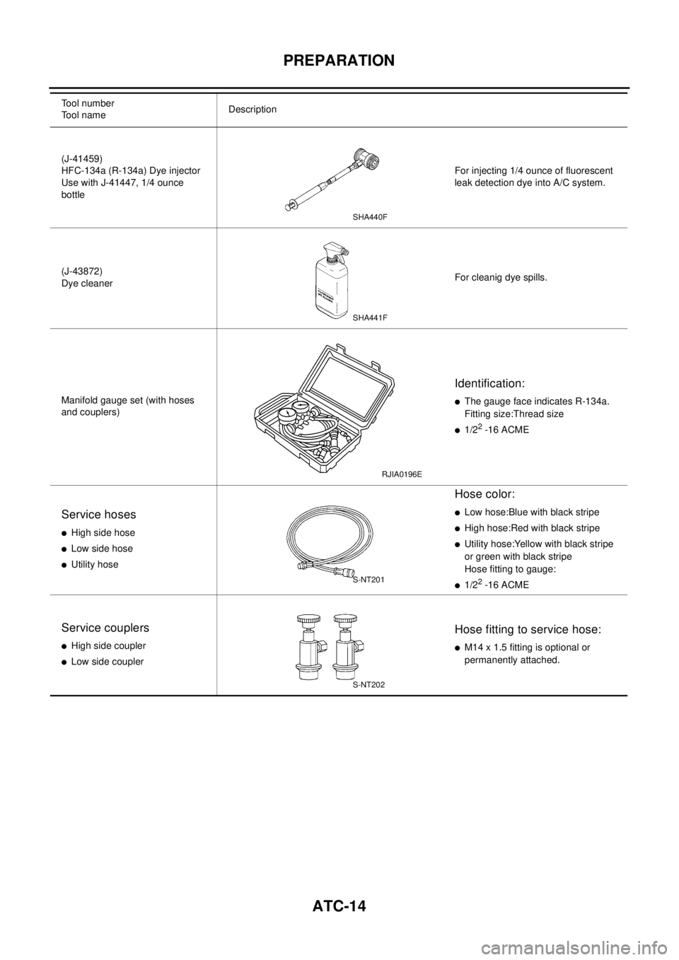
(J-41459)
HFC-134a (R-134a) Dye injector
Use with J-41447, 1/4 ounce
bottleFor injecting 1/4 ounce of fluorescent
leak detection dye into A/C system.
(J-43872)
Dye cleanerFor cleanig dye spills.
Manifold gauge set (with hoses
and couplers)
Identification:
lThe gauge face indicates R-134a.
Fitting size:Thread size
l1/22-16 ACME
Service hoses
lHigh side hose
lLow side hose
lUtility hose
Hose color:
lLow hose:Blue with black stripe
lHigh hose:Red with black stripe
lUtility hose:Yellow with black stripe
or green with black stripe
Hose fitting to gauge:
l1/22-16 ACME
Service couplers
lHigh side coupler
lLow side coupler
Hose fitting to service hose:
lM14 x 1.5 fitting is optional or
permanently attached. Tool number
Tool nameDescription
SHA440F
SHA441F
RJIA0196E
S-NT201
S-NT202
Page 2026 of 3066
![NISSAN X-TRAIL 2003 Electronic Repair Manual EM-56
[QR20DE]
CYLINDER HEAD
5. Remove valve oil seal with valve oil seal puller.
6. When valve seat must be replaced, refer toEM-58, "
VA LV E
SEAT REPLACEMENT"to removal.
7. When valve guide must be NISSAN X-TRAIL 2003 Electronic Repair Manual EM-56
[QR20DE]
CYLINDER HEAD
5. Remove valve oil seal with valve oil seal puller.
6. When valve seat must be replaced, refer toEM-58, "
VA LV E
SEAT REPLACEMENT"to removal.
7. When valve guide must be](/img/5/57402/w960_57402-2025.png)
EM-56
[QR20DE]
CYLINDER HEAD
5. Remove valve oil seal with valve oil seal puller.
6. When valve seat must be replaced, refer toEM-58, "
VA LV E
SEAT REPLACEMENT"to removal.
7. When valve guide must be replaced, refer toEM-57, "
VA LV E
GUIDE REPLACEMENT"to removal.
8. Remove spark plug with spark plug wrench.
ASSEMBLY
1. Install valve guide. Refer toEM-57, "VALVE GUIDE REPLACEMENT".
2. Install valve seat. Refer toEM-58, "
VALVE SEAT REPLACEMENT".
3. Install valve oil seal.
lInstall with valve oil seal drift to match dimension in illustra-
tion.
4. Install valve.
lInstall larger diameter to intake side.
5. Install valve spring.
lInstall smaller pitch (valve spring seat side) to cylinder head
side.
lConfirm identification color of valve spring.
Intake: Blue
Exhaust : Yellow
6. Install valve spring retainer.
7. Install valve collet.
lCompress valve spring with valve spring compressor. Install
valve collet with magnet hand.
lTap stem edge lightly with plastic hammer after installation to
check its installed condition.
8. Install valve lifter.
9. Install spark plug with spark plug wrench.
Inspection After DisassemblyEBS009R6
CYLINDER HEAD DISTORTION
1. Wipe off oil and remove water scale (like deposit), gasket,
sealer, carbon, etc with scraper.
CAUTION:
Use utmost care not to allow gasket debris to enter pas-
sages for oil or water.
2. At each of several locations on bottom surface of cylinder head,
measuredistortioninsixdirections.
SEM093F
KBIA0135E
PBIC0525E
Standard : 0.1mm (0.004 in)
PBIC0075E
Page 2028 of 3066
![NISSAN X-TRAIL 2003 Electronic Repair Manual EM-58
[QR20DE]
CYLINDER HEAD
3. Ream cylinder head valve guide hole.
4. Heat cylinder head to 110 to 130°C (230 to 266°F) by soaking in
heated oil.
5. Press valve guide from camshaft side to dimensi NISSAN X-TRAIL 2003 Electronic Repair Manual EM-58
[QR20DE]
CYLINDER HEAD
3. Ream cylinder head valve guide hole.
4. Heat cylinder head to 110 to 130°C (230 to 266°F) by soaking in
heated oil.
5. Press valve guide from camshaft side to dimensi](/img/5/57402/w960_57402-2027.png)
EM-58
[QR20DE]
CYLINDER HEAD
3. Ream cylinder head valve guide hole.
4. Heat cylinder head to 110 to 130°C (230 to 266°F) by soaking in
heated oil.
5. Press valve guide from camshaft side to dimensions as in illus-
tration.
6. Using valve guide reamer, apply reamer finish to valve guide.
VA LV E S E AT C O N TA C T
lAfter confirming that the dimensions of valve guides and valves
are within specifications, perform this procedure.
lApply prussian blue (or white lead) onto contacting surface of
valve seat to check the condition of the valve contact on the sur-
face.
lCheck if the contact area band is continuous all around the cir-
cumference.
lIf not, grind to adjust valve fitting and check again. If the contact-
ing surface still has N.G conditions even after the re-check,
replace valve seat.
VALVE SEAT REPLACEMENT
When valve seat is removed, replace with oversized (0.5 mm, 0.020 in) valve seat.
1. Bore out old seat until it collapses. Boring should not continue beyond the bottom face of the seat recess
in cylinder head. Set the machine depth stop to ensure this.Valve guide hole diameter (for service parts)
Intake and exhaust
: 10.175 - 10.196 mm (0.4006 - 0.4014 in)
SEM932C
PBIC0078E
Standard
Intake and exhaust : 6.000- 6.018 mm (0.2362- 0.2369
in)
SEM932C
EMA0487D
Page 2030 of 3066
![NISSAN X-TRAIL 2003 Electronic Repair Manual EM-60
[QR20DE]
CYLINDER HEAD
VALVE SPRING SQUARENESS
Set try square along the side of valve spring and rotate the spring.
Measure the maximum clearance between the top face of spring and
try square.
V NISSAN X-TRAIL 2003 Electronic Repair Manual EM-60
[QR20DE]
CYLINDER HEAD
VALVE SPRING SQUARENESS
Set try square along the side of valve spring and rotate the spring.
Measure the maximum clearance between the top face of spring and
try square.
V](/img/5/57402/w960_57402-2029.png)
EM-60
[QR20DE]
CYLINDER HEAD
VALVE SPRING SQUARENESS
Set try square along the side of valve spring and rotate the spring.
Measure the maximum clearance between the top face of spring and
try square.
VALVE SPRING DIMENSIONS AND VALVE SPRING PRESSURE LOAD
Check valve spring pressure with valve spring seat installed at spec-
ified spring height.
CAUTION:
Do not remove valve spring seat.Limit : More than 1.9 mm (0.0748 in)
PBIC0080E
Standard: INTAKE EXHAUST
Free height 44.84-45.34 mm
(1.7654-1.7850
in)45.28-45.78 mm
(1.7827-1.8024 in)
Installation
height35.30 mm (1.390
in)35.30 mm (1.390
in)
Installation
load151-175 N (15.4-
17.8 kg, 34-39 lb)151-175 N (15.4-
17.8 kg, 34-39 lb)
Height during
valve open24.94 mm
(0.9819 in)26.39 mm (1.0390
in)
Load with
valve open358-408 N (36.5-
41.6 kg, 80-92 lb)325-371 N (33.1-
37.8 kg, 73-83 lb)
Identification
colorBlue Yellow
SEM113
Page 2049 of 3066
![NISSAN X-TRAIL 2003 Electronic Repair Manual CYLINDER BLOCK
EM-79
[QR20DE]
C
D
E
F
G
H
I
J
K
L
MA
EM
Main Bearing Selection Table (No.2 and 4 journals)
Main Bearing Grade Table (All Journals)
Unit: mm (in)
KBIA0150E
Grade number ThicknessIdentif NISSAN X-TRAIL 2003 Electronic Repair Manual CYLINDER BLOCK
EM-79
[QR20DE]
C
D
E
F
G
H
I
J
K
L
MA
EM
Main Bearing Selection Table (No.2 and 4 journals)
Main Bearing Grade Table (All Journals)
Unit: mm (in)
KBIA0150E
Grade number ThicknessIdentif](/img/5/57402/w960_57402-2048.png)
CYLINDER BLOCK
EM-79
[QR20DE]
C
D
E
F
G
H
I
J
K
L
MA
EM
Main Bearing Selection Table (No.2 and 4 journals)
Main Bearing Grade Table (All Journals)
Unit: mm (in)
KBIA0150E
Grade number ThicknessIdentification color
(UPR / LWR)Remarks
0 1.973 - 1.976 (0.0777 - 0.0778) Black
Grade and color are the same
for upper and lower bearings. 1 1.976 - 1.979 (0.0778 - 0.0779) Brown
2 1.979 - 1.982 (0.0779- 0.0780) Green
3 1.982 - 1.985 (0.0780 - 0.0781) Yellow
4 1.985 - 1.988 (0.0781 - 0.0783) Blue
5 1.988 - 1.991 (0.0783 - 0.0784) Pink
6 1.991 - 1.994 (0.0784 - 0.0785) Purple
7 1.994 - 1.997 (0.0785 - 0.0786) White
Page 2050 of 3066
![NISSAN X-TRAIL 2003 Electronic Repair Manual EM-80
[QR20DE]
CYLINDER BLOCK
Use Undersize Bearing Usage Guide
lUse undersize (US) bearing when oil clearance with standard size main bearing is not within specification.
lWhen using undersize (US) b NISSAN X-TRAIL 2003 Electronic Repair Manual EM-80
[QR20DE]
CYLINDER BLOCK
Use Undersize Bearing Usage Guide
lUse undersize (US) bearing when oil clearance with standard size main bearing is not within specification.
lWhen using undersize (US) b](/img/5/57402/w960_57402-2049.png)
EM-80
[QR20DE]
CYLINDER BLOCK
Use Undersize Bearing Usage Guide
lUse undersize (US) bearing when oil clearance with standard size main bearing is not within specification.
lWhen using undersize (US) bearing, measure the bearing inner diameter with bearing installed, and grind
journal until oil clearance falls within specification.
Bearing undersize table
Unit: mm (in)
CAUTION:
Keep fillet R when grinding crankshaft journal in order to use
undersize bearing (All journals).
Inspection After DisassemblyEBS009RA
CRANKSHAFT SIDE CLEARANCE
lUsing a dial gauge, measure the clearance between the thrust
bearings and the crankshaft arm when the crankshaft is moved
fully forward or backward.
lIf the measured value exceeds the limit, replace the thrust bear-
ings, and measure again. If it still exceeds the limit, replace the
crankshaft also.
01UPR 1.973 - 1.976 (0.0777 - 0.0778)
Black / Brown
Grade and color are different
for upper and lower bearings. LWR 1.976 - 1.979 (0.0778 - 0.0779)
12UPR 1.976 - 1.979 (0.0778 - 0.0779)
Brown / Green
LWR 1.979 - 1.982 (0.0779 - 0.0780)
23UPR 1.979 - 1.982 (0.0779- 0.0780)
Green / Yellow
LWR 1.982 - 1.985 (0.0780 - 0.0781)
34UPR 1.982 - 1.985 (0.0780 - 0.0781)
Ye l l o w / B l u e
LWR 1.985 - 1.988 (0.0781 - 0.0783)
45UPR 1.985 - 1.988 (0.0781 - 0.0783)
Blue / Pink
LWR 1.988 - 1.991 (0.0783 - 0.0784)
56UPR 1.988 - 1.991 (0.0783 - 0.0784)
Pink / Purple
LWR 1.991 - 1.994 (0.0784 - 0.0785)
67UPR 1.991 - 1.994 (0.0784 - 0.0785)
Purple / White
LWR 1.994 - 1.997 (0.0785 - 0.0786) Grade number ThicknessIdentification color
(UPR / LWR)Remarks
Size Thickness
US 0.25 (0.0098) 2.106 - 2.114 (0.0829 - 0.0832)
KBIA0148E
Standard : 0.10 - 0.26 mm (0.0039 - 0.0102 in)
Limit : 0.30 mm (0.0118 in)
PBIC0268E
Page 2068 of 3066
![NISSAN X-TRAIL 2003 Electronic Repair Manual EM-98
[QR20DE]
SERVICE DATA AND SPECIFICATIONS (SDS)
*: Total indicator reading
MAIN BEARING
Unit: mm (in) Free end playStandard 0.10 - 0.26 (0.0039 - 0.0102)
Limit 0.30 (0.0118)
SEM645SEM715
Grade nu NISSAN X-TRAIL 2003 Electronic Repair Manual EM-98
[QR20DE]
SERVICE DATA AND SPECIFICATIONS (SDS)
*: Total indicator reading
MAIN BEARING
Unit: mm (in) Free end playStandard 0.10 - 0.26 (0.0039 - 0.0102)
Limit 0.30 (0.0118)
SEM645SEM715
Grade nu](/img/5/57402/w960_57402-2067.png)
EM-98
[QR20DE]
SERVICE DATA AND SPECIFICATIONS (SDS)
*: Total indicator reading
MAIN BEARING
Unit: mm (in) Free end playStandard 0.10 - 0.26 (0.0039 - 0.0102)
Limit 0.30 (0.0118)
SEM645SEM715
Grade number ThicknessIdentification color
(UPR / LWR)Remarks
0 1.973 - 1.976 (0.0777 - 0.0778) Black
Grade and color are the same
for upper and lower bearings. 1 1.976 - 1.979 (0.0778 - 0.0779) Brown
2 1.979 - 1.982 (0.0779 - 0.0780) Green
3 1.982 - 1.985 (0.0780 - 0.0781) Yellow
4 1.985 - 1.988 (0.0781 - 0.0783) Blue
5 1.988 - 1.991 (0.0783 - 0.0784) Pink
6 1.991 - 1.994 (0.0784 - 0.0785) Purple
7 1.994 - 1.997 (0.0785 - 0.0786) White
SEM685D