mirror NISSAN X-TRAIL 2003 Electronic Repair Manual
[x] Cancel search | Manufacturer: NISSAN, Model Year: 2003, Model line: X-TRAIL, Model: NISSAN X-TRAIL 2003Pages: 3066, PDF Size: 51.47 MB
Page 1 of 3066
MODEL T30 SERIES
2001 NISSAN EUROPE N.V.
All rights reserved. No part of this Electronic Service Manual may be reproduced or stored in a retrieval system, or transmitted in any
form, or by any means, electronic, mechanical, photocopying, recording or otherwise, without the prior written permission of Nissan
Europe N.V., Paris, France.
A GENERAL INFORMATION
B ENGINE
C TRANSMISSION/
TRANSAXLE
D DRIVELINE/AXLE
E SUSPENSION
F BRAKES
G STEERING
H RESTRAINTS
I BODY
J AIR CONDITIONER
K ELECTRICAL
L MAINTENANCE
M INDEXGI General Information
EM Engine Mechanical
LU Engine Lubrication System
CO Engine Cooling System
EC Engine Control System
FL Fuel System
EX Exhaust System
ACC Accelerator Control System
CL Clutch
MT Manual Transaxle
AT Automatic Transaxle
TF Transfer
PR Propeller Shaft
RFD Rear Final Drive
FAX Front Axle
RAX Rear Axle
FSU Front Suspension
RSU Rear Suspension
WT Road Wheels & Tires
BR Brake System
PB Parking Brake System
BRC Brake Control System
PS Power Steering System
SB Seat Belts
SRS Supplemental Restraint System (SRS)
BL Body, Lock & Security System
GW Glasses, Window System & Mirrors
RF Roof
EI Exterior & Interior
IP Instrument Panel
SE Seat
ATC Automatic Air Conditioner
MTC Manual AIr Conditioner
SC Starting & Charging System
LT Lighting System
DI Driver Information System
WW Wiper, Washer & Horn
BCS Body Control System
LAN LAN System
AV Audio, Visual & Telephone System
PG Power Supply, Ground & Circuit Elements
MA Maintenance
IDX Alphabetical Index
QUICK REFERENCE INDEX
A
B
C
D
E
F
G
H
I
J
K
L
M
Page 719 of 3066

REFRIGERANT LINES
ATC-141
C
D
E
F
G
H
I
K
L
MA
B
AT C
CAUTION:
Moving the electronic leak detector probe slower and closer to the suspected leak area will improve
the chances of finding a leak.
Checking System for Leaks Using the Fluorescent Leak DetectorEJS000VK
1. Check A/C system for leaks using the UV lamp and safety glasses (J-42220) in a low sunlight area (area
without windows preferable). Illuminate all components, fittings and lines. The dye will appear as a bright
green/yellow area at the point of leakage. Fluorescent dye observed at the evaporator drain opening indi-
cates an evaporator core assembly (tubes, core or TXV) leak.
2. If the suspected area is difficult to see, use an adjustable mirror or wipe the area with a clean shop rag or
cloth, with the UV lamp for dye residue.
3. After the leak is repaired, remove any residual dye using dye cleaner (J-43872) to prevent future misdiag-
nosis.
4. Perform a system performance check and verify the leak repair with an approved electronic refrigerant
leak detector.
NOTE:
Other gases in the work area or substances on the A/C components, for example, anti-freeze, windshield
washer fluid, solvents and lubricants, may falsely trigger the leak detector. Make sure the surfaces to be
checked are clean.
Clean with a dry cloth or blow off with shop air.
Do not allow the sensor tip of the detector to contact with any substance. This can also cause false readings
and may damage the detector.
Dye InjectionEJS000VL
(This procedure is only necessary when recharging the system or when the compressor has seized and was
replaced.)
1. Check A/C system static (at rest) pressure. Pressure must be at least 345 kPa (50 psi).
2. Pour one bottle (1/4 ounce / 7.4 cc) of the A/C refrigerant dye into the injector tool (J-41459).
3. Connect the injector tool to the A/C LOW PRESSURE side service fitting.
4. Start engine and switch A/C ON.
5. When the A/C operating (compressor running), inject one bottle (1/4 ounce / 7.4 cc) of fluorescent dye
through the low-pressure service valve using dye injector tool J-41459 (refer to the manufacture's operat-
ing instructions).
6. With the engine still running, disconnect the injector tool from the service fitting.
CAUTION:
Be careful the A/C system or replacing a component, pour the dye directly into the open system con-
nection and proceed with the service procedures.
7. Operate the A/C system for a minimum of 20 minutes to mix the dye with the system oil. Depending on the
leak size, operating conditions and location of the leak, it may take from minutes to days for the dye to
penetrate a leak and become visible.
Electronic Refrigerant Leak DetectorEJS000VM
PRECAUTIONS FOR HANDLING LEAK DETECTOR
When performing a refrigerant leak check, use an A/C leak detector
or equivalent. Ensure that the instrument is calibrated and set prop-
erly per the operating instructions.
The leak detector is a delicate device. In order to use the leak detec-
tor properly, read the operating instructions and perform any speci-
fied maintenance.
SHA705EB
Page 1954 of 3066
EI-14
DOOR OUTSIDE MOLDING
DOOR OUTSIDE MOLDING
PFP:82820
Removal and InstallationEIS0015E
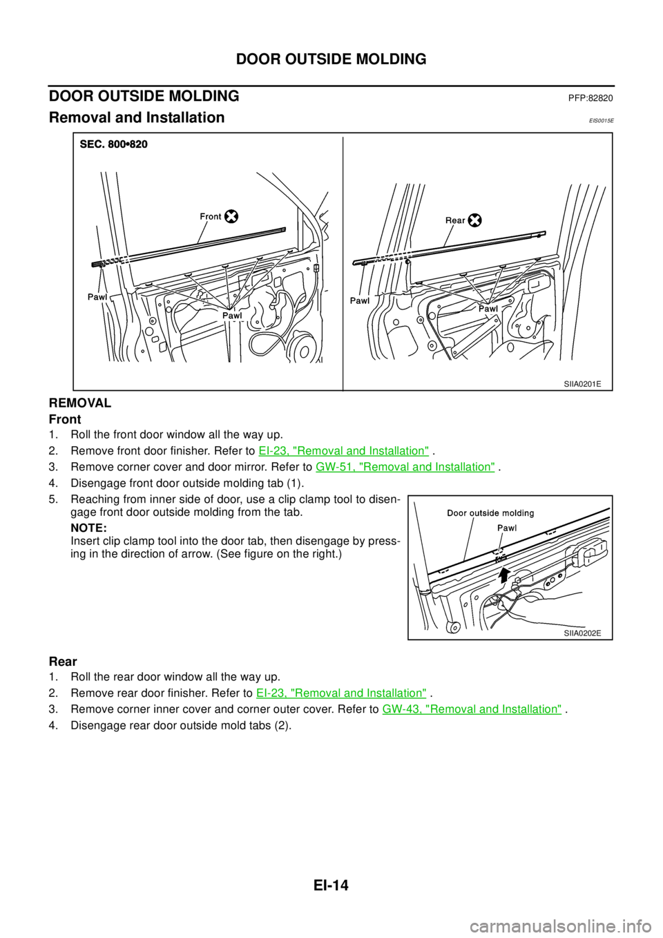
REMOVAL
Front
1. Roll the front door window all the way up.
2. Remove front door finisher. Refer toEI-23, "
Removal and Installation".
3. Remove corner cover and door mirror. Refer toGW-51, "
Removal and Installation".
4. Disengage front door outside molding tab (1).
5. Reaching from inner side of door, use a clip clamp tool to disen-
gage front door outside molding from the tab.
NOTE:
Insert clip clamp tool into the door tab, then disengage by press-
inginthedirectionofarrow.(Seefigureontheright.)
Rear
1. Roll the rear door window all the way up.
2. Remove rear door finisher. Refer toEI-23, "
Removal and Installation".
3. Remove corner inner cover and corner outer cover. Refer toGW-43, "
Removal and Installation".
4. Disengage rear door outside mold tabs (2).
SIIA0201E
SIIA0202E
Page 1969 of 3066
HEADLINING
EI-29
C
D
E
F
G
H
J
K
L
MA
B
EI
HEADLININGPFP:73910
Removal and InstallationEIS000ND
REMOVAL
1. Remove front pillar and center pillar garnishes. Refer toEI-26, "Removal and Installation".
2. Remove body side welt. Refer toEI-26, "
Removal and Installation".
SIIA0223E
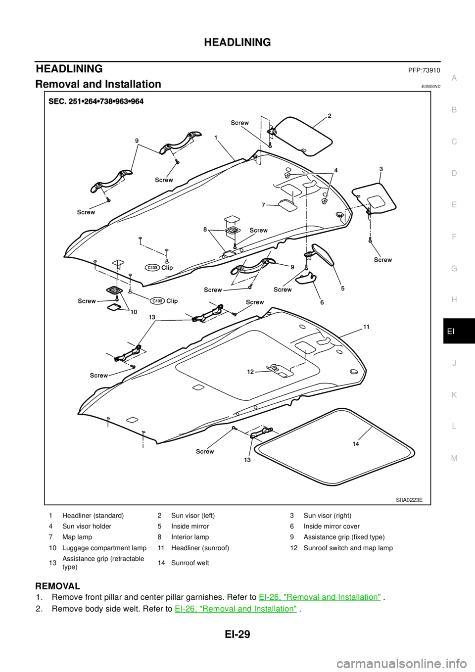
1 Headliner (standard) 2 Sun visor (left) 3 Sun visor (right)
4 Sun visor holder 5 Inside mirror 6 Inside mirror cover
7 Map lamp 8 Interior lamp 9 Assistance grip (fixed type)
10 Luggage compartment lamp 11 Headliner (sunroof) 12 Sunroof switch and map lamp
13Assistance grip (retractable
type)14 Sunroof welt
Page 1970 of 3066
EI-30
HEADLINING
3. Remove rear pillar finisher. Refer toEI-26, "Removal and Installation".
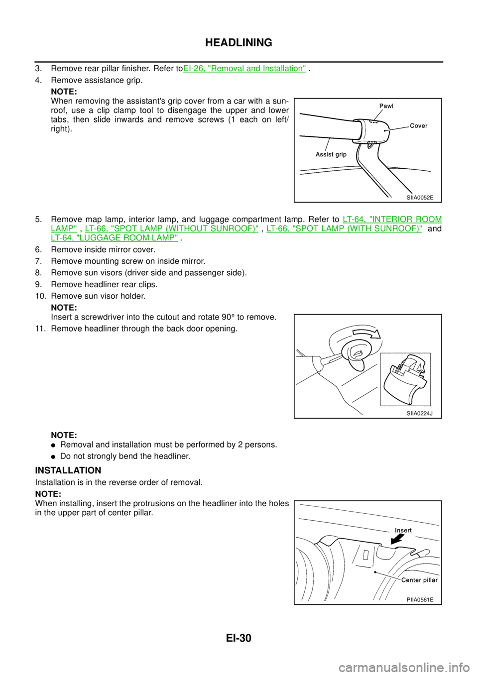
4. Remove assistance grip.
NOTE:
When removing the assistant's grip cover from a car with a sun-
roof, use a clip clamp tool to disengage the upper and lower
tabs, then slide inwards and remove screws (1 each on left/
right).
5. Remove map lamp, interior lamp, and luggage compartment lamp. Refer toLT-64, "
INTERIOR ROOM
LAMP",LT-66, "SPOT LAMP (WITHOUT SUNROOF)",LT- 6 6 , "SPOT LAMP (WITH SUNROOF)"and
LT-64, "
LUGGAGE ROOM LAMP".
6. Remove inside mirror cover.
7. Remove mounting screw on inside mirror.
8. Remove sun visors (driver side and passenger side).
9. Remove headliner rear clips.
10. Remove sun visor holder.
NOTE:
Insert a screwdriver into the cutout and rotate 90°to remove.
11. Remove headliner through the back door opening.
NOTE:
lRemoval and installation must be performed by 2 persons.
lDo not strongly bend the headliner.
INSTALLATION
Installation is in the reverse order of removal.
NOTE:
When installing, insert the protrusions on the headliner into the holes
in the upper part of center pillar.
SIIA0052E
SIIA0224J
PIIA0561E
Page 1990 of 3066
![NISSAN X-TRAIL 2003 Electronic Repair Manual EM-20
[QR20DE]
INTAKE MANIFOLD
Tightening Intake Manifold collector bolts and nuts
lTighten in numerical order as shown in the figure.
NOTE:
No.6 means double tightening of bolts 1.
Installation of El NISSAN X-TRAIL 2003 Electronic Repair Manual EM-20
[QR20DE]
INTAKE MANIFOLD
Tightening Intake Manifold collector bolts and nuts
lTighten in numerical order as shown in the figure.
NOTE:
No.6 means double tightening of bolts 1.
Installation of El](/img/5/57402/w960_57402-1989.png)
EM-20
[QR20DE]
INTAKE MANIFOLD
Tightening Intake Manifold collector bolts and nuts
lTighten in numerical order as shown in the figure.
NOTE:
No.6 means double tightening of bolts 1.
Installation of Electric Throttle Control Actuator
lTighten fixing bolts of electric throttle control actuator equally and diagonally in several steps.
lAfter installation perform procedure inEM-20, "INSPECTION AFTER INSTALLATION".
Connecting Quick Connector of Fuel Hose
lInstall quick connector as follows. (The steps are the same for quick connectors on engine side and vehi-
cle)
1. Make sure no foreign substances are deposited in and around tube and quick connector and no damage
on them.
2. Thinly apply new engine oil around the fuel tube tip end.
3. Align center to insert quick connector straightly into fuel tube.
lInsert fuel tube into quick connector until the first spool on fuel
tubes is inserted completely and the second one is positioned
slightly below the quick connectors bottom end.
CAUTION:
lHold A position in illustration when inserting fuel tube
into quick connector.
lCarefully align center to avoid inclined insertion to pre-
vent damage to O-ring inside quick connector.
lInsert until you hear a “click” sound and actually feel the
engagement.
lTo avoid misidentification of engagement with a similar sound, be sure to perform the next step.
4. Before clamping fuel hose with hose clamps, pull quick connector hard by hand holding A position. Make
sure it is completely engaged (connected) so that it does not come out from fuel tube.
NOTE:
Recommended pulling force is 50 N (5.1 kg, 11.2 lb).
5. Install quick connector cap on quick connector joint.
lDirect arrow mark on quick connector cap to upper side (The
figure shows quick connector cap for engine side).
6. Install fuel hose to hose clamp.
INSPECTION AFTER INSTALLATION
lCheck connections for fuel leakage.
1. Start the engine, and run it for a few minutes with engine at idle.
2. Stop the engine, and check for fuel leakage both visually and by odor of gasoline.
NOTE:
Use mirrors for checking on invisible points.
KBIA0234E
KBIA0272E
KBIA0298E
Page 2000 of 3066
![NISSAN X-TRAIL 2003 Electronic Repair Manual EM-30
[QR20DE]
FUEL INJECTOR AND FUEL TUBE
INSTALLATION
1. Install O-rings to fuel injector paying attention to the items below.
lLubricate O-rings by smearing new engine oil.
lBe careful not to scrat NISSAN X-TRAIL 2003 Electronic Repair Manual EM-30
[QR20DE]
FUEL INJECTOR AND FUEL TUBE
INSTALLATION
1. Install O-rings to fuel injector paying attention to the items below.
lLubricate O-rings by smearing new engine oil.
lBe careful not to scrat](/img/5/57402/w960_57402-1999.png)
EM-30
[QR20DE]
FUEL INJECTOR AND FUEL TUBE
INSTALLATION
1. Install O-rings to fuel injector paying attention to the items below.
lLubricate O-rings by smearing new engine oil.
lBe careful not to scratch it with a tool or fingernails during installation. Also be careful not to twist
or stretch O-ring. If O-ring was stretched while it is attached, do no insert it into fuel tube immedi-
atly.
2. Install fuel injector to fuel tube with the following procedure.
lInsert clip into clip mounting groove on fuel injector.
lInsert clip so that projection A of fuel injector matches notch A of
the clip.
lDo not reuse clip. Replace it with a new one.
lBe careful to keep clip from interfering with O-ring. If interfer-
ence occurs, replace O-ring.
3. Insert fuel injector into fuel tube with clip attached.
lInsertitwhilematchingittotheaxialcenter.
lInsert fuel injector so that projection B of fuel injector matches
notch B of the clip.
lMake sure that fuel tube flange is securely fixed in flange fixing
groove on clip.
lMake sure that installation is complete by checking that fuel
injector does not rotate or come off.
4. Install fuel tube assembly with the following procedure.
a. Insert the tip of each fuel injector into intake manifold.
b. Tighten mounting bolts in two steps in the numerical order
shown in the figure.
5. Install intake manifold collector. Refer toEM-17, "
INTAKE MANI-
FOLD".
6. Connect fuel hose. Refer toEM-17, "
INTAKE MANIFOLD".
7. Install all removed parts in the reverse order of removal.
INSPECTION AFTER INSTALLATION
lCheck connections for fuel leakage.
1. Start the engine, and run it for a few minutes with engine at idle.
2. Stop the engine, and check for fuel leakage both visually and by odor of gasoline.
NOTE:
Use mirrors for checking on invisible points.
CAUTION:
Do not touch the engine immediately after stopped as engine becomes extremely hot.
KBIA0240E
1st step: 9.3 - 10.8 N·m (0.95 - 1.1 kg-m, 0.7 - 0.8 ft-lb)
2nd step: 20.6 - 26.5 N·m (2.1 - 2.7 kg-m, 16 - 19 ft-lb)
KBIA0239E
Page 2304 of 3066

GW-1
GLASSES, WINDOW SYSTEM & MIRRORS
IBODY
CONTENTS
C
D
E
F
G
H
J
K
L
M
SECTION
A
B
GW
GLASSES, WINDOW SYSTEM & MIRRORS
PRECAUTIONS .......................................................... 2
Precautions for Supplemental Restraint System
(SRS) “AIR BAG” and “SEAT BELT PRE-TEN-
SIONER” .................................................................. 2
Precautions .............................................................. 2
WINDSHIELD GLASS AND MOLDING ..................... 3
Removal and Installation .......................................... 3
REMOVAL ............................................................. 3
INSTALLATION ..................................................... 3
SIDE WINDOW GLASS .............................................. 5
Removal and Installation .......................................... 5
REMOVAL ............................................................. 5
INSTALLATION ..................................................... 5
BACK DOOR WINDOW GLASS ................................ 7
Removal and Installation .......................................... 7
REMOVAL ............................................................. 7
INSTALLATION ..................................................... 8
REAR WINDOW DEFOGGER .................................... 9
Component Parts and Harness Connector Location..... 9
System description ................................................... 9
Wiring Diagram –DEF– LHD models ..................... 10
Terminals and Reference value for Time Control
Unit (LHD models) .................................................. 12
Wiring Diagram –DEF– RHD models ..................... 13
Terminals and Reference value for Time Control
Unit (RHD models) ................................................. 15
Trouble Diagnoses ................................................. 15
DIAGNOSTIC PROCEDURE SUBTITLE
(SYMPTOM: REAR WINDOW DEFOGGER
DOES NOT ACTIVATE, OR DOES NOT GO OFF
AFTER ACTIVATING.) ........................................ 15
Electrical Components Inspection .......................... 17
REAR WINDOW DEFOGGER RELAY ............... 17
REAR WINDOW DEFOGGER SWITCH ............. 17
FILAMENT CHECK ............................................. 17
FILAMENT REPAIR ............................................ 18
POWER WINDOW SYSTEM .................................... 20
Component Parts and Harness Connector Location... 20
System Description ................................................ 20MANUAL OPERATION ........................................ 20
AUTO OPERATION ............................................. 21
POWER WINDOW LOCK ................................... 21
TIME FUNCTION ................................................ 21
DRIVER WINDOW ANTI–PINCH FUNCTION .... 21
Schematic (LHD models) ........................................ 23
Wiring Diagram – WINDOW – (LHD models) ......... 24
Terminal and Reference Value for Power Window
Main Switch (LHD models) ..................................... 28
Terminal and Reference Value for Each Door's
Power Window Switch (LHD models) ..................... 29
Schematic (RHD models) ....................................... 31
Wiring Diagram – WINDOW – RHD models ........... 32
Terminal and Reference Value for Power Window
Main Switch (RHD models) .................................... 36
Terminal and Reference Value for Each Door's
Power Window Switch (RHD models) .................... 37
Trouble Diagnoses ................................................. 38
Encoder and Limit Switch Check ............................ 39
FRONT DOOR GLASS AND REGULATOR ............. 41
Removal and Installation ........................................ 41
INSPECTION AFTER REMOVAL ....................... 42
INSPECTION AFTER INSTALLATION ................ 42
FITTING INSPECTION ....................................... 42
REAR DOOR GLASS AND REGULATOR ............... 43
Removal and Installation ........................................ 43
INSPECTION AFTER REMOVAL ....................... 45
FITTING INSPECTION ....................................... 45
DOOR MIRROR ........................................................ 46
Precautions to Handle Retractable Power Door Mir-
rors ......................................................................... 46
Wiring Diagram –MIRROR– LHD models .............. 47
Wiring Diagram –MIRROR– RHD models .............. 49
Removal and Installation ........................................ 51
REMOVAL ........................................................... 51
INSTALLATION ................................................... 51
Disassembly and Assembly .................................... 52
DISASSEMBLY ................................................... 52
ASSEMBLY ......................................................... 52
Page 2312 of 3066
REAR WINDOW DEFOGGER
GW-9
C
D
E
F
G
H
J
K
L
MA
B
GW
REAR WINDOW DEFOGGERPFP:25350
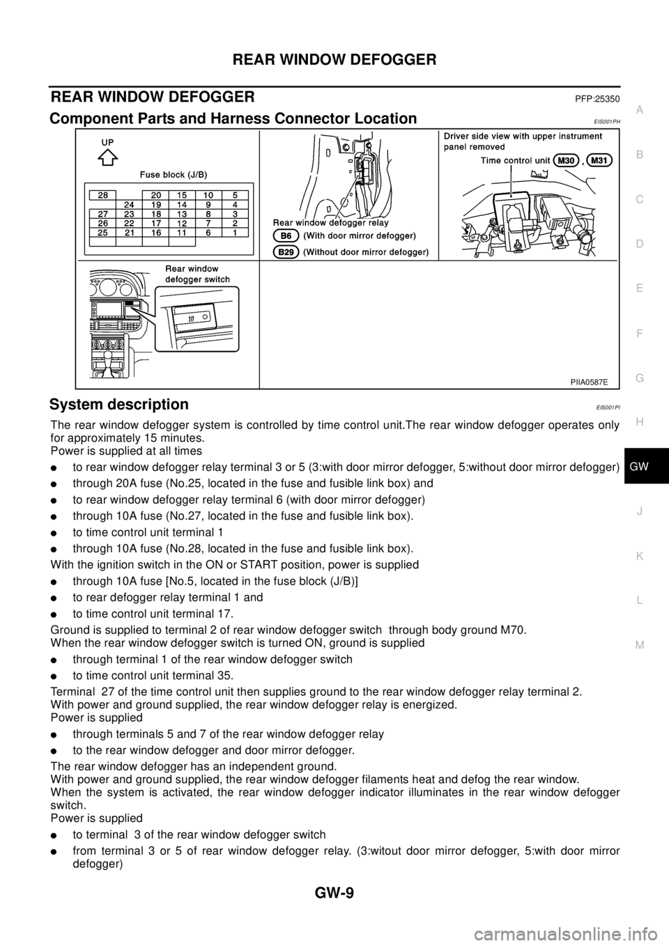
Component Parts and Harness Connector LocationEIS001PH
System descriptionEIS001PI
The rear window defogger system is controlled by time control unit.The rear window defogger operates only
for approximately 15 minutes.
Power is supplied at all times
lto rear window defogger relay terminal 3 or 5 (3:with door mirror defogger, 5:without door mirror defogger)
lthrough 20A fuse (No.25, located in the fuse and fusible link box) and
lto rear window defogger relay terminal 6 (with door mirror defogger)
lthrough 10A fuse (No.27, located in the fuse and fusible link box).
lto time control unit terminal 1
lthrough 10A fuse (No.28, located in the fuse and fusible link box).
With the ignition switch in the ON or START position, power is supplied
lthrough 10A fuse [No.5, located in the fuse block (J/B)]
lto rear defogger relay terminal 1 and
lto time control unit terminal 17.
Ground is supplied to terminal 2 of rear window defogger switch through body ground M70.
When the rear window defogger switch is turned ON, ground is supplied
lthrough terminal 1 of the rear window defogger switch
lto time control unit terminal 35.
Terminal 27 of the time control unit then supplies ground to the rear window defogger relay terminal 2.
With power and ground supplied, the rear window defogger relay is energized.
Power is supplied
lthrough terminals 5 and 7 of the rear window defogger relay
lto the rear window defogger and door mirror defogger.
The rear window defogger has an independent ground.
With power and ground supplied, the rear window defogger filaments heat and defog the rear window.
When the system is activated, the rear window defogger indicator illuminates in the rear window defogger
switch.
Power is supplied
lto terminal 3 of the rear window defogger switch
lfrom terminal 3 or 5 of rear window defogger relay. (3:witout door mirror defogger, 5:with door mirror
defogger)
PIIA0587E
Page 2318 of 3066
REAR WINDOW DEFOGGER
GW-15
C
D
E
F
G
H
J
K
L
MA
B
GW
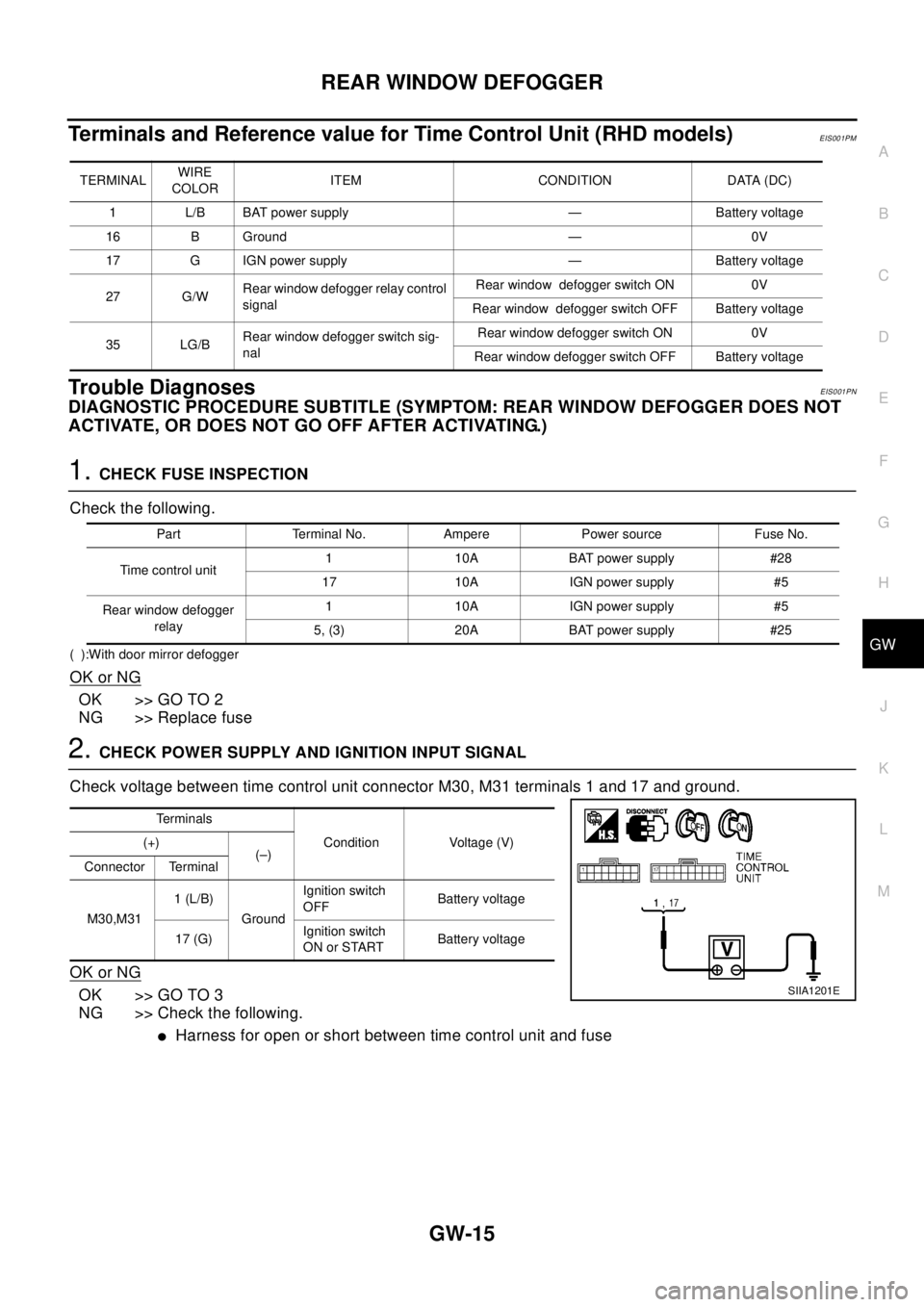
Terminals and Reference value for Time Control Unit (RHD models)EIS001PM
Trouble DiagnosesEIS001PN
DIAGNOSTIC PROCEDURE SUBTITLE (SYMPTOM: REAR WINDOW DEFOGGER DOES NOT
ACTIVATE, OR DOES NOT GO OFF AFTER ACTIVATING.)
1.CHECK FUSE INSPECTION
Check the following.
( ):With door mirror defogger
OK or NG
OK >> GO TO 2
NG >> Replace fuse
2.CHECK POWER SUPPLY AND IGNITION INPUT SIGNAL
Check voltage between time control unit connector M30, M31 terminals 1 and 17 and ground.
OK or NG
OK >> GO TO 3
NG >> Check the following.
lHarness for open or short between time control unit and fuse
TERMINALWIRE
COLORITEM CONDITION DATA (DC)
1 L/B BAT power supply — Battery voltage
16 B Ground — 0V
17 G IGN power supply — Battery voltage
27 G/WRear window defogger relay control
signalRear window defogger switch ON 0V
Rear window defogger switch OFF Battery voltage
35 LG/BRear window defogger switch sig-
nalRear window defogger switch ON 0V
Rear window defogger switch OFF Battery voltage
Part Terminal No. Ampere Power source Fuse No.
Time control unit1 10A BAT power supply #28
17 10A IGN power supply #5
Rear window defogger
relay1 10A IGN power supply #5
5, (3) 20A BAT power supply #25
Te r m i n a l s
Condition Voltage (V) (+)
(–)
Connector Terminal
M30,M311(L/B)
GroundIgnition switch
OFFBattery voltage
17 (G)Ignition switch
ON or STARTBattery voltage
SIIA1201E