sunroof NISSAN X-TRAIL 2003 Electronic Repair Manual
[x] Cancel search | Manufacturer: NISSAN, Model Year: 2003, Model line: X-TRAIL, Model: NISSAN X-TRAIL 2003Pages: 3066, PDF Size: 51.47 MB
Page 1969 of 3066
HEADLINING
EI-29
C
D
E
F
G
H
J
K
L
MA
B
EI
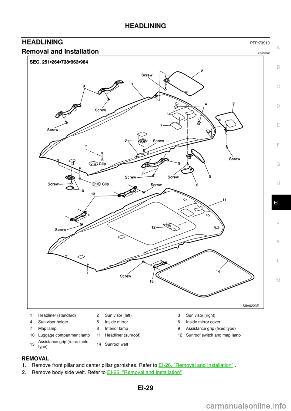
HEADLININGPFP:73910
Removal and InstallationEIS000ND
REMOVAL
1. Remove front pillar and center pillar garnishes. Refer toEI-26, "Removal and Installation".
2. Remove body side welt. Refer toEI-26, "
Removal and Installation".
SIIA0223E
1 Headliner (standard) 2 Sun visor (left) 3 Sun visor (right)
4 Sun visor holder 5 Inside mirror 6 Inside mirror cover
7 Map lamp 8 Interior lamp 9 Assistance grip (fixed type)
10 Luggage compartment lamp 11 Headliner (sunroof) 12 Sunroof switch and map lamp
13Assistance grip (retractable
type)14 Sunroof welt
Page 1970 of 3066
EI-30
HEADLINING
3. Remove rear pillar finisher. Refer toEI-26, "Removal and Installation".
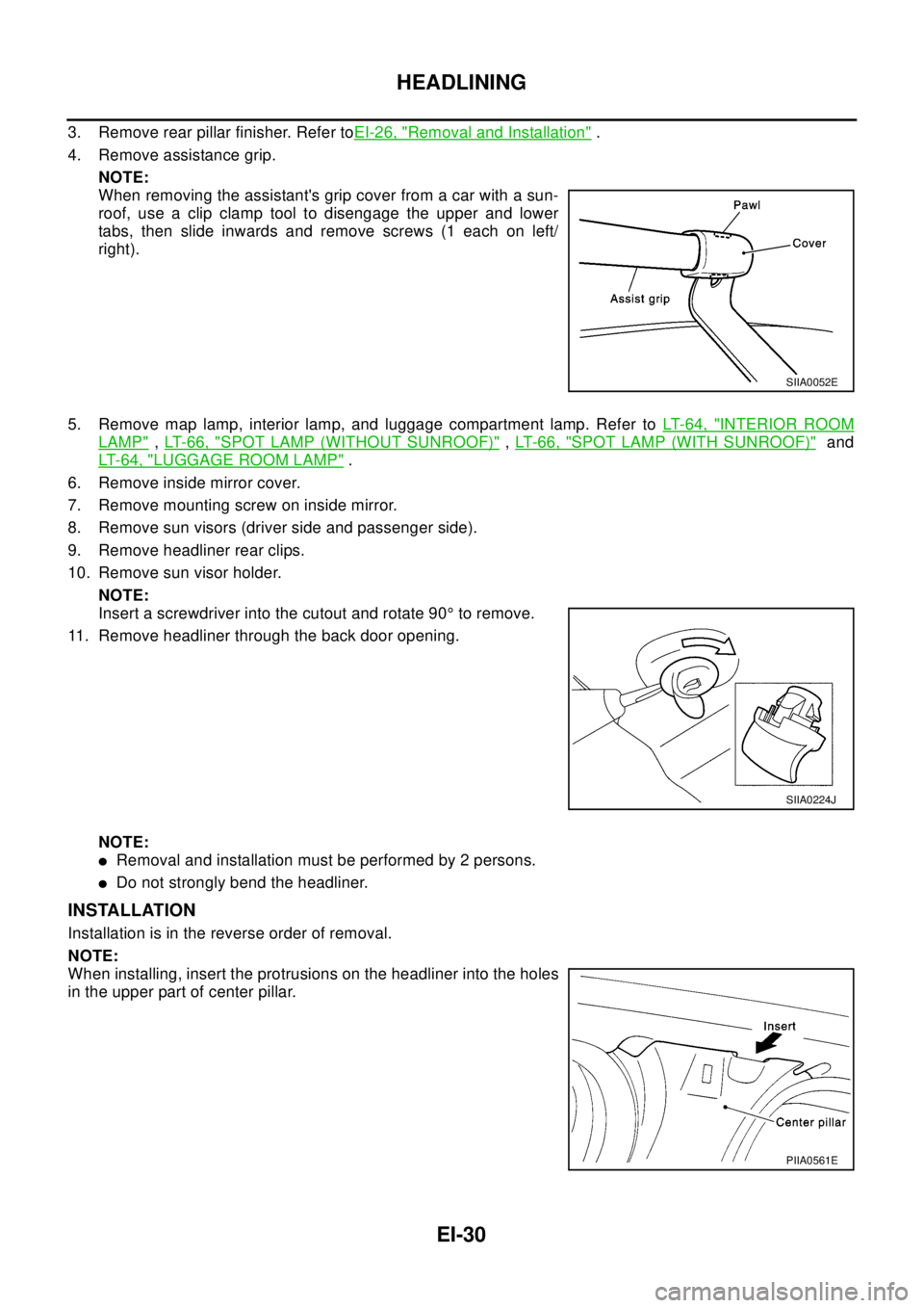
4. Remove assistance grip.
NOTE:
When removing the assistant's grip cover from a car with a sun-
roof, use a clip clamp tool to disengage the upper and lower
tabs, then slide inwards and remove screws (1 each on left/
right).
5. Remove map lamp, interior lamp, and luggage compartment lamp. Refer toLT-64, "
INTERIOR ROOM
LAMP",LT-66, "SPOT LAMP (WITHOUT SUNROOF)",LT- 6 6 , "SPOT LAMP (WITH SUNROOF)"and
LT-64, "
LUGGAGE ROOM LAMP".
6. Remove inside mirror cover.
7. Remove mounting screw on inside mirror.
8. Remove sun visors (driver side and passenger side).
9. Remove headliner rear clips.
10. Remove sun visor holder.
NOTE:
Insert a screwdriver into the cutout and rotate 90°to remove.
11. Remove headliner through the back door opening.
NOTE:
lRemoval and installation must be performed by 2 persons.
lDo not strongly bend the headliner.
INSTALLATION
Installation is in the reverse order of removal.
NOTE:
When installing, insert the protrusions on the headliner into the holes
in the upper part of center pillar.
SIIA0052E
SIIA0224J
PIIA0561E
Page 2365 of 3066
IDX-8
ALPHABETICAL INDEX
SRS - See Supplemental Restraint System .....SRS-5
SRS - Wiring diagram/LHD .............................SRS-10
SRS - Wiring diagram/RHD ............................SRS-12
SRS Trouble diagnoses ....................................SRS-7
Stall test (A/T) ......................................AT-65,AT-287
Standardized relay .............................................PG-74
START - Wiring diagram ........................SC-22,SC-23
Start signal ..........................EC-348,EC-623,EC-818
Starter ................................................................SC-21
Starting system ..................................................SC-21
Steering gear and linkage inspection ................MA-40
Steering knuckle ................................................FAX-7
Steering linkage .................................................PS-12
Steering wheel and column .......................PS-6,PS-9
Stop lamp ................................................LT-26,LT-42
Stop lamp switch ................................EC-329,EC-562
STOP/L - Wiring diagram ........................LT-26,LT-42
Strut (rear) ........................................................RSU-8
Suction control valve ........................................EC-772
Sunload sensor ...............ATC-98,ATC-100,ATC-107
Sunroof ................................................................RF-2
Super lock ..........................................................BL-24
Supplemental Restraint System .......................SRS-5
Supplemental restraint system - Wiring diagram/LHD ..
SRS-10
Supplemental restraint system - Wiring diagram/RHD .
SRS-12
Suspension .......................................................MA-41
Symbols and abbreviations .................................GI-22
Symptom matrix chart ...........EC-69,EC-417,EC-676
Synchronizer (M/T) ...............................MT-19,MT-24
System readiness test (SRT) code ....................EC-40
T
T/MTR - Wiring diagram ....................EC-275
,EC-538
Tachometer ................................................DI-4,DI-22
Tail lamp .................................................LT-30,LT-40
TAIL/L - Wiring diagram ......................................LT-30
Tailgate lamp ......................................................LT-30
TCM circuit diagram ...........................................AT-16
TCM inspection table .........................AT-126,AT-348
THEFT - Wiring diagram ....................................BL-65
Theft warning system .........................................BL-65
Thermal protector ............................................ATC-81
Thermostat(QR20DE) .......................................CO-21
Thermostat(YD22DDTi) ....................................CO-43
Three way catalyst function .............................EC-229
Three way catalyst(QR20DE) ...........................EM-22
Throttle control motor relay ................EC-279,EC-542
Throttle position sensor (TPS) ...........EC-146,EC-475
Throttle position switch ......................AT-266,AT-388
Time control system ..........................................BCS-3
Timing chain(QR20DE) .....................................EM-43
Timing chain(YD22DDTi) ..................EM-158,EM-163
TM/RLY - Wiring diagram ..................EC-281,EC-544
Torque converter installation .............AT-459,AT-556
TPS - Wiring diagram ........................EC-149,EC-479
Transfer case .....................................................TF-23
Transfer control unit inspection table ......TF-42,TF-49
Transmission case (M/T) ......................MT-18,MT-23
Trouble diagnoses ..............................................GI-10
Turbocharger charge air cooler(YD22DDTi) ...EM-114
Turbocharger(YD22DDTi) ...............................EM-119
TURN - Wiring diagram ..........................LT-17,LT-19
Turn signal lamp .....................................LT-17,LT-42
Two trip detection logic .......................EC-36,EC-401
V
Vacuum hose (brake system) ............................BR-19
Vacuum hose drawing (Engine control)EC-23,EC-388
Vacuum pump(YD22DDTi) .............................EM-131
Valve clearance(QR20DE) ...............................EM-40
Valve clearance(YD22DDTi) ...........................EM-154
Valve guide(QR20DE) ......................................EM-57
Valve guide(YD22DDTi) .................................EM-180
Valve lifter(QR20DE) ........................................EM-33
Valve lifter(YD22DDTi) ...................................EM-152
Valve seat(QR20DE) ........................................EM-58
Valve seat(YD22DDTi) ...................................EM-181
Valve spring(QR20DE) .....................................EM-60
Valve spring(YD22DDTi) ................................EM-183
VDC -Wiring diagram ......................................BRC-65
Vehicle speed sensor (VSS)EC-239,EC-513,EC-744
Ventilation air filter ........................................ATC-114
Viscosity number (SAE) ....................................MA-18
VSS - Wiring diagram .........EC-241,EC-515,EC-745
W
Warning chime ....................................................DI-52
Warning lamps ....................................................DI-39
Washer, front .....................................................WW-4
Washer, rear ....................................................WW-13
Water control valve(QR20DE) ..........................CO-21
Water pump(QR20DE) .....................................CO-19
Water pump(YD22DDTi) ...................................CO-40
Water temperature gauge ..........................DI-4,DI-22
Weatherstrip - See Exterior ...............................BL-10
Wheel alignment (front) ....................................FSU-6
Wheel alignment (rear) .....................................RSU-6
Wheel balance ..................................................MA-38
Wheel bearing (front axle) .................................FAX-7
Wheel bearing (rear) .........................................RAX-6
Wheel hub (front) ...............................................FAX-7
Wheel hub (rear) ...............................................RAX-6
Wheel sensor(VDC) ......................................BRC-119
Wheel sensors (ABS) .....................................BRC-48
WINDOW - Wiring diagram ..............................GW-24
Window, back ....................................................GW-7
Window, back door ............................................GW-7
Window, door ......................................GW-41,GW-43
Window, rear side ..............................................GW-5
Window, side - See Rear side window ..............GW-5
Windshield .........................................................GW-3
Page 2400 of 3066

LT-2
LICENSE PLATE LAMP ...................................... 32
Removal and Installation ........................................ 32
PARKING AND TAIL LAMPS ............................... 32
LICENSE PLATE LAMP ...................................... 32
FRONT FOG LAMP .................................................. 33
System Description ................................................. 33
DESCRIPTION .................................................... 33
FOG LAMP OPERATION .................................... 33
Wiring Diagram — F/FOG — .................................. 34
Aiming Adjustment .................................................. 35
Bulb Replacement .................................................. 36
Removal and Installation ........................................ 36
REMOVAL ........................................................... 36
INSTALLATION .................................................... 36
REAR FOG LAMP ..................................................... 37
Wiring Diagram -R/FOG-/Without Front Fog Lamp... 37
Wiring Diagram -R/FOG-/With Front Fog Lamp ..... 38
Bulb Replacement .................................................. 39
Removal and Installation ........................................ 39
REMOVAL ........................................................... 39
INSTALLATION .................................................... 39
CLEARANCE LAMP/TAIL LAMP ............................. 40
Bulb Rplacement (Clearance Lamp) ...................... 40
Bulb Replacement (Taillamp) .................................. 40
Removal and Installation of Clearance Lamp ......... 40
Removal and Installation of Taillamp ...................... 40
HIGH-MOUNTED STOP LAMP ................................ 41
Bulb Replacement .................................................. 41
Removal and Installation ........................................ 41
REAR COMBINATION LAMP ................................... 42
Wiring Diagram —STOP/L— .................................. 42
Bulb Replacement .................................................. 43
Removal and Installation ........................................ 43
REMOVAL ........................................................... 43
INSTALLATION .................................................... 43COMBINATION SWITCH ..........................................44
Removal and Installation .........................................44
Switch Circuit Inspection .........................................44
ILLUMINATION ..........................................................45
System Description .................................................45
Schematic ...............................................................46
Wiring Diagram -ILL-/LHD MODELS ......................47
Wiring Diagram -ILL-/RHD MODELS ......................51
INTERIOR ROOM LAMP ..........................................55
System Description .................................................55
POWER SUPPLY AND GROUND .......................55
SWITCH OPERATION .........................................55
INTERIOR ROOM LAMP TIMER OPERATION ... 55
ON-OFF CONTROL .............................................56
Wiring Diagram -ROOM/L- ......................................57
Interior Room Lamp Timer Does Not Operate ........59
Interior Room Lamp Timer Does Not Cancel ..........62
Bulb Replacement ...................................................63
INTERIOR ROOM LAMP .....................................63
LUGGAGE ROOM LAMP ....................................63
Removal and Installation .........................................64
INTERIOR ROOM LAMP .....................................64
LUGGAGE ROOM LAMP ....................................64
SPOT LAMPS ............................................................65
Wiring Diagram -INT/L- ...........................................65
Bulb Replacement ...................................................66
SPOT LAMP (WITHOUT SUNROOF) .................66
SPOT LAMP (WITH SUNROOF) .........................66
Removal and Installation .........................................66
SPOT LAMP (WITHOUT SUNROOF) .................66
SPOT LAMP (WITH SUNROOF) .........................66
BULB SPECIFICATIONS ..........................................67
Headlamp ................................................................67
Exterior Lamp ..........................................................67
Interior Lamp/Illumination ........................................67
Page 2464 of 3066
LT-66
SPOT LAMPS
Bulb Replacement
EKS003DD
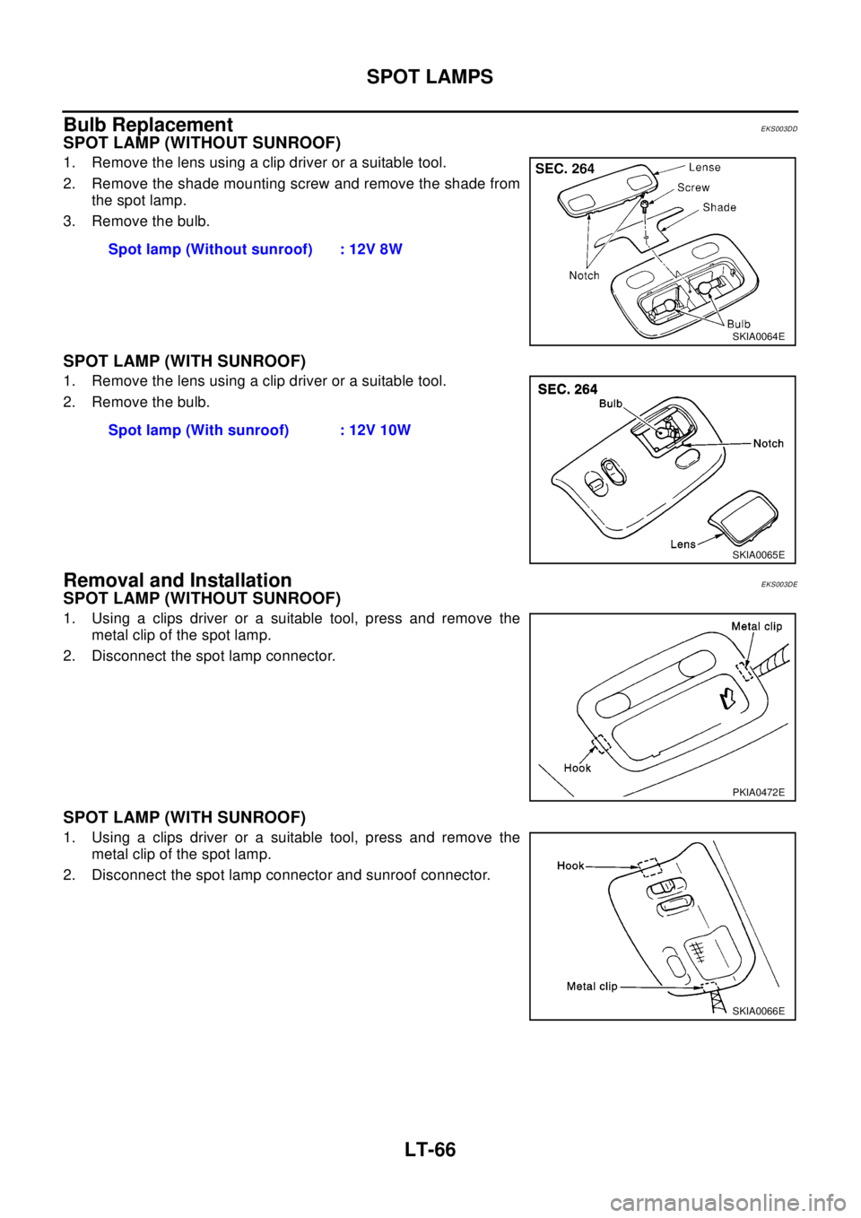
SPOT LAMP (WITHOUT SUNROOF)
1. Remove the lens using a clip driver or a suitable tool.
2. Remove the shade mounting screw and remove the shade from
the spot lamp.
3. Remove the bulb.
SPOT LAMP (WITH SUNROOF)
1. Remove the lens using a clip driver or a suitable tool.
2. Remove the bulb.
Removal and InstallationEKS003DE
SPOT LAMP (WITHOUT SUNROOF)
1. Using a clips driver or a suitable tool, press and remove the
metal clip of the spot lamp.
2. Disconnect the spot lamp connector.
SPOT LAMP (WITH SUNROOF)
1. Using a clips driver or a suitable tool, press and remove the
metal clip of the spot lamp.
2. Disconnect the spot lamp connector and sunroof connector.Spot lamp (Without sunroof) : 12V 8W
SKIA0064E
Spot lamp (With sunroof) : 12V 10W
SKIA0065E
PKIA0472E
SKIA0066E
Page 2465 of 3066

BULB SPECIFICATIONS
LT-67
C
D
E
F
G
H
I
J
L
MA
B
LT
BULB SPECIFICATIONSPFP:26297
HeadlampEKS003GS
Exterior LampEKS003GT
Interior Lamp/IlluminationEKS003GU
Item Wattage (W)
Low/High55 /60(H4)
Item Wattage (W)
Front combination lamp Clearance lamp 5
Front turn signal lamp21(amber)
Side turn signal lamp5
Fog lampFront fog lamp 55(H3)
Rear fog lamp 21
Rear combination lampStop/Tail lamp 21/5
Turn signal lamp 21
Back-up lamp 21
License plate lamp5
High-mounted stop lamp5
Item Wattage (W)
Interior room lamp10
Spot lampWithout sunroof 8
With sunroof 10
Luggage room lamp10
Page 2534 of 3066
MA-42
CHASSIS AND BODY MAINTENANCE
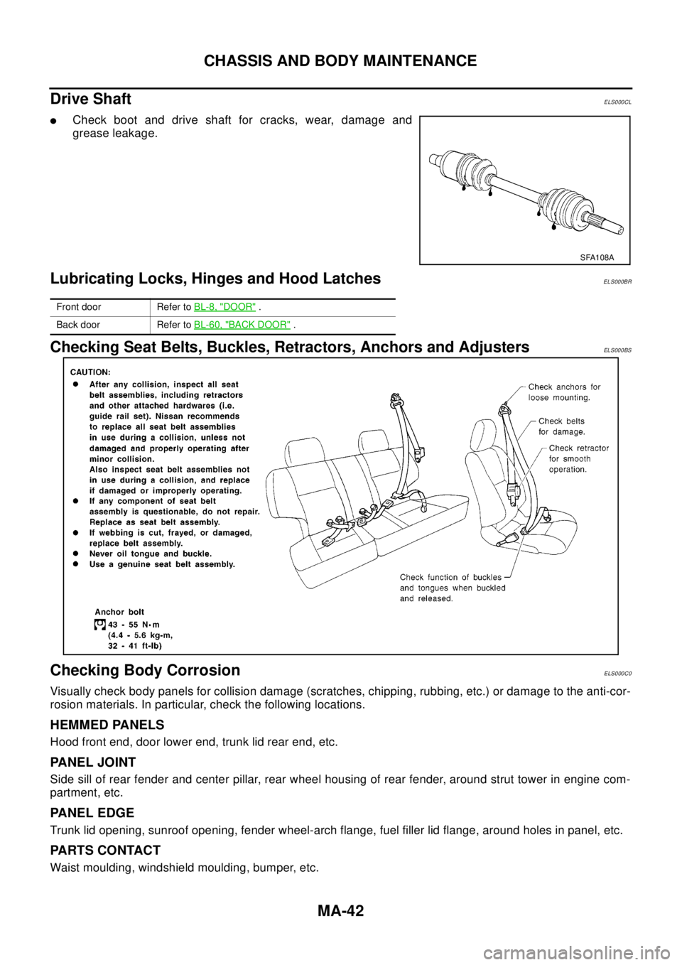
Drive Shaft
ELS000CL
lCheck boot and drive shaft for cracks, wear, damage and
grease leakage.
Lubricating Locks, Hinges and Hood LatchesELS000BR
Checking Seat Belts, Buckles, Retractors, Anchors and AdjustersELS000BS
Checking Body CorrosionELS000C0
Visually check body panels for collision damage (scratches, chipping, rubbing, etc.) or damage to the anti-cor-
rosion materials. In particular, check the following locations.
HEMMED PANELS
Hood front end, door lower end, trunk lid rear end, etc.
PANEL JOINT
Side sill of rear fender and center pillar, rear wheel housing of rear fender, around strut tower in engine com-
partment, etc.
PANEL EDGE
Trunk lid opening, sunroof opening, fender wheel-arch flange, fuel filler lid flange, around holes in panel, etc.
PA R T S C O N TA C T
Waist moulding, windshield moulding, bumper, etc.
SFA108A
Front door Refer toBL-8, "DOOR".
Back door Refer toBL-60, "
BACK DOOR".
Page 2738 of 3066

PG-62
HARNESS
HO2S1H EC Heated Oxygen Sensor 1 (Front)
HO2S2 EC Heated Oxygen Sensor 1 (Rear)
HO2S2H EC Heated Oxygen Sensor 1 (Rear)
HORN WW Horn
IATS EC Intake Air Temperature Sensor
IATSEN EC Intake Air Temperature Sensor
IGNSYS EC Ignition Signal
ILL LT Illumination
INJECT EC Injector
INT/L LT Map Lamp
IVC EC Intake Valve Timing Control Solenoid Valve
IVC/V EC Intake Valve Timing Control Solenoid Valve
KS EC Knock Sensor (KS)
LOAD EC Electrical Load Signal
LPSV AT Line Pressure Solenoid Valve
MAFS EC MassAirFlowSensor(MAFS)
MAIN EC, AT Main Power Supply and Ground Circuit
METER DI Meter and Gauge
MIL EC Malfunction Indicator Lamp
MIL/DL EC MIL and Data Link Connector
MIRROR GW Door Mirror
MULTI BL Multi-Remote Control System
NATS BL Nissan Anti-Theft System
NONDTC AT Non-Detective Items
OVRCSV AT Overrun Clutch Solenoid Valve
PGC/V EC EVAP Canister Purge Volume Control Solenoid Valve
PHASE EC Camshaft Position Sensor (PHASE)
PNP/SW EC, AT Park/Neutral Position (PNP) Switch
PNPSW1 EC Park/Neutral Position (PNP) Switch
POS EC Crankshaft Position Sensor (CKPS)(POS)
POWER PG Power Supply Routing
PRGVLV EC EVAP Canister Purge Volume Control Solenoid Valve
PRWIRE BL Theft Warning System (Pre-wire)
PS/SEN EC Power Steering Pressure Sensor
PST/SW EC Power Steering Oil Pressure Switch
R/FOG LT Rear Fog Lamp
ROOM/L LT Interior Room Lamp
RP/SEN EC Refrigerant Pressure Sensor
RRO2 EC Heated Oxygen Sensor 2 (Rear)
RRO2/H EC Heated Oxygen Sensor 2 Heater (Rear)
S/LOCK BL Super Lock
S/SIG EC Start Signal
SCTC/V EC Suction Control Valve
SHIFT AT A/T Shift Lock System
SROOF BL Sunroof
SRS SRS Supplemental Restraint System (SRS)
SSV/A AT Shift Solenoid Valve A
SSV/B AT Shift Solenoid Valve B
START SC Starting System
STOP/L LT Stop Lamp
T/MTR EC Throttle Control Motor
TAIL/L LT Parking, License and Tail Lamps
Page 2813 of 3066

RF-1
ROOF
IBODY
CONTENTS
C
D
E
F
G
H
J
K
L
M
SECTION
A
B
RF
ROOF
SUNROOF .................................................................. 2
Precautions .............................................................. 2
System Description .................................................. 2
RESUMING OPERATION ..................................... 2
Component Parts Location ....................................... 2
Wiring Diagram — SROOF — ................................. 3
Terminal and Reference Value for Sunroof Switch..... 5
Wind Deflector Inspection ........................................ 5
Sunroof Lid Weatherstrip Inspection ........................ 5
Link and Wire Assembly Inspection ......................... 5Fitting Adjustment ..................................................... 6
LONGITUDINAL/LATERAL CLEARANCE
ADJUSTMENT ...................................................... 6
SURFACE MISMATCH ADJUSTMENT ................ 6
Removal and Installation .......................................... 7
SUNROOF UNIT ................................................... 8
GLASS LID ............................................................ 9
SUNSHADE .......................................................... 9
WIND DEFLECTOR ............................................ 10
SUNROOF MOTOR ............................................ 10
Page 2814 of 3066
RF-2
SUNROOF
SUNROOF
PFP:91210
PrecautionsEIS000MJ
lIf sunroof motor operation sound is noted but sunroof does not operate, replace motor assembly with
glass lid fully closed.
lIf sunroof (glass lid and motor) does not operate when using sunroof switch then remove the front cover of
the luggage compartment, and rotate motor gear box drive shaft with the emergency handle (in the tool
box).
System DescriptionEIS000MK
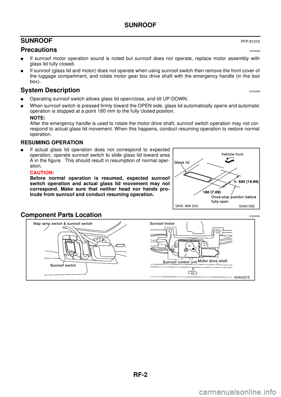
lOperating sunroof switch allows glass lid open/close, and tilt UP·DOWN.
lWhen sunroof switch is pressed firmly toward the OPEN side, glass lid automatically opens and automatic
operation is stopped at a point 180 mm to the fully closed position.
NOTE:
After the emergency handle is used to rotate the motor drive shaft, sunroof switch operation may not cor-
respond to actual glass lid movement. When this happens, conduct resuming operation to restore normal
operation.
RESUMING OPERATION
lIf actual glass lid operation does not correspond to expected
operation, operate sunroof switch to slide glass lid toward area
A in the figure. This should result in resumption of normal oper-
ation.
CAUTION:
Before normal operation is resumed, expected sunroof
switch operation and actual glass lid movement may not
correspond. Make sure that neither head nor hands pro-
trude from sunroof and conduct resuming operation.
Component Parts LocationEIS000ML
SIIA0139E
SIIA0321E