wheel torque NISSAN X-TRAIL 2003 Electronic Repair Manual
[x] Cancel search | Manufacturer: NISSAN, Model Year: 2003, Model line: X-TRAIL, Model: NISSAN X-TRAIL 2003Pages: 3066, PDF Size: 51.47 MB
Page 38 of 3066
AT-32
OVERALL SYSTEM
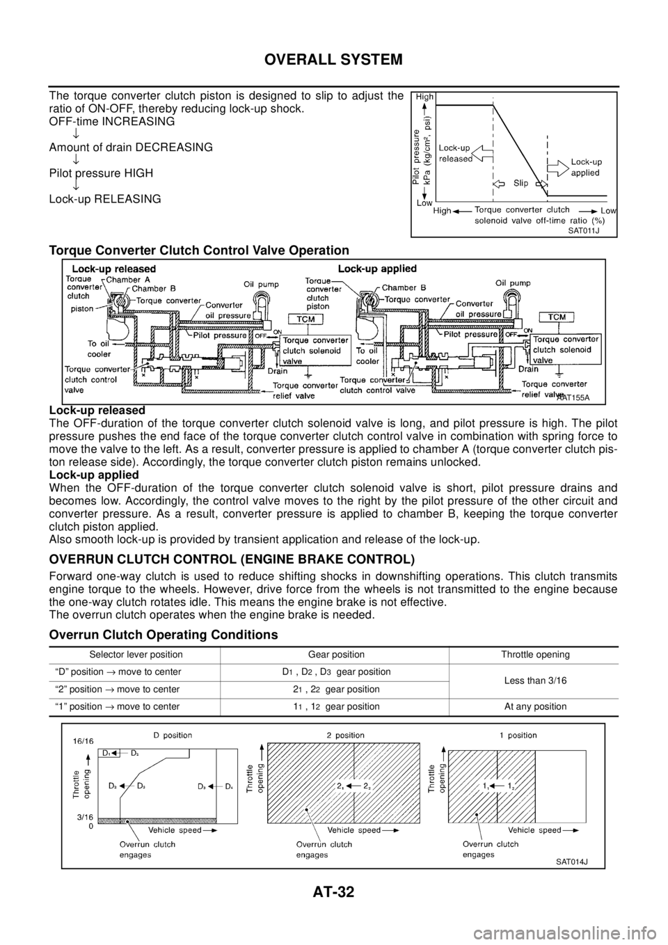
The torque converter clutch piston is designed to slip to adjust the
ratio of ON-OFF, thereby reducing lock-up shock.
OFF-time INCREASING
ÂŻ
Amount of drain DECREASING
ÂŻ
Pilot pressure HIGH
ÂŻ
Lock-up RELEASING
Torque Converter Clutch Control Valve Operation
Lock-up released
The OFF-duration of the torque converter clutch solenoid valve is long, and pilot pressure is high. The pilot
pressure pushes the end face of the torque converter clutch control valve in combination with spring force to
move the valve to the left. As a result, converter pressure is applied to chamber A (torque converter clutch pis-
ton release side). Accordingly, the torque converter clutch piston remains unlocked.
Lock-up applied
When the OFF-duration of the torque converter clutch solenoid valve is short, pilot pressure drains and
becomes low. Accordingly, the control valve moves to the right by the pilot pressure of the other circuit and
converter pressure. As a result, converter pressure is applied to chamber B, keeping the torque converter
clutch piston applied.
Also smooth lock-up is provided by transient application and release of the lock-up.
OVERRUN CLUTCH CONTROL (ENGINE BRAKE CONTROL)
Forward one-way clutch is used to reduce shifting shocks in downshifting operations. This clutch transmits
engine torque to the wheels. However, drive force from the wheels is not transmitted to the engine because
the one-way clutch rotates idle. This means the engine brake is not effective.
The overrun clutch operates when the engine brake is needed.
Overrun Clutch Operating Conditions
SAT011J
AAT155A
Selector lever position Gear position Throttle opening
“D” position®move to center D
1,D2,D3gear position
Less than 3/16
“2” position®move to center 2
1,22gear position
“1” position®move to center 1
1,12gear position At any position
SAT014J
Page 465 of 3066
![NISSAN X-TRAIL 2003 Electronic Repair Manual REMOVAL AND INSTALLATION
AT-459
[ALL]
D
E
F
G
H
I
J
K
L
MA
B
AT
12. Remove center member, engine insulator and engine mounting
bracket.
lTighten center member fixing bolts to specified torque, Refer
t NISSAN X-TRAIL 2003 Electronic Repair Manual REMOVAL AND INSTALLATION
AT-459
[ALL]
D
E
F
G
H
I
J
K
L
MA
B
AT
12. Remove center member, engine insulator and engine mounting
bracket.
lTighten center member fixing bolts to specified torque, Refer
t](/img/5/57402/w960_57402-464.png)
REMOVAL AND INSTALLATION
AT-459
[ALL]
D
E
F
G
H
I
J
K
L
MA
B
AT
12. Remove center member, engine insulator and engine mounting
bracket.
lTighten center member fixing bolts to specified torque, Refer
toEM-61, "
ENGINE ASSEMBLY".
13. Remove suspension member. Refer toFSU-12, "
FRONT SUS-
PENSION MEMBER".
14. Remove dust cover from converter housing.
Rotate crankshaft to gain access to securing bolts.
15. Remove securing bolts between drive plate and torque con-
verter. when crank shaft rotates, turn to right at the front side of
engine.
16. Support engine with a jack.
17. Remove bolts fixing transaxle to engine.
18. Lower transaxle while supporting it with a jack.
InstallationECS004ND
1. Check drive plate runout.
CAUTION:
Do not allow any magnetic materials to contact the ring
gear teeth.
lIf this runout is out of allowance, replace drive plate with ring
gear.
2. When connecting torque converter to transaxle, measure dis-
tance “A” to be certain that they are correctly assembled.
SCIA0794E
AAT259A
Maximum allowable runout :
Refer to EM-´´, “FLYWHEEL/DRIVE PLATE RUNOUT”.
SAT977H
Distance “A”: 19 mm (0.626 in) or more
SAT573D
Page 845 of 3066
BRAKE PIPING AND HOSE
BR-11
C
D
E
G
H
I
J
K
L
MA
B
BR
BRAKE PIPING AND HOSEPFP:46210
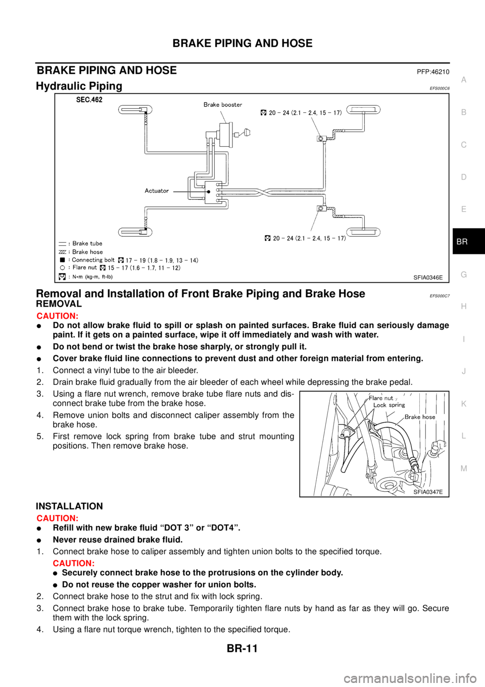
Hydraulic PipingEFS000C6
Removal and Installation of Front Brake Piping and Brake HoseEFS000C7
REMOVAL
CAUTION:
lDo not allow brake fluid to spill or splash on painted surfaces. Brake fluid can seriously damage
paint. If it gets on a painted surface, wipe it off immediately and wash with water.
lDo not bend or twist the brake hose sharply, or strongly pull it.
lCover brake fluid line connections to prevent dust and other foreign material from entering.
1. Connect a vinyl tube to the air bleeder.
2. Drain brake fluid gradually from the air bleeder of each wheel while depressing the brake pedal.
3. Using a flare nut wrench, remove brake tube flare nuts and dis-
connect brake tube from the brake hose.
4. Remove union bolts and disconnect caliper assembly from the
brake hose.
5. First remove lock spring from brake tube and strut mounting
positions. Then remove brake hose.
INSTALLATION
CAUTION:
lRefill with new brake fluid “DOT 3” or “DOT4”.
lNever reuse drained brake fluid.
1. Connect brake hose to caliper assembly and tighten union bolts to the specified torque.
CAUTION:
lSecurely connect brake hose to the protrusions on the cylinder body.
lDo not reuse the copper washer for union bolts.
2. Connect brake hose to the strut and fix with lock spring.
3. Connect brake hose to brake tube. Temporarily tighten flare nuts by hand as far as they will go. Secure
them with the lock spring.
4. Using a flare nut torque wrench, tighten to the specified torque.
SFIA0346E
SFIA0347E
Page 846 of 3066
BR-12
BRAKE PIPING AND HOSE
5. Refill brake fluid until new brake fluid comes out of each air bleeder.
6. Afterwards, bleed air.
Removal and Installation of Rear Brake Piping and Brake HoseEFS000C8
REMOVAL
CAUTION:
lDo not allow brake fluid to spill or splash on painted surfaces. Brake fluid can seriously damage
paint. If it gets on a painted surface, wipe it off immediately and wash with water.
lDo not bend or twist the brake hose sharply, or strongly pull it.
lCover brake fluid line connections to prevent dust and other foreign material from entering.
1. Connect a vinyl tube to the air bleeder.
2. Drain brake fluid gradually from the air bleeder of each wheel while depressing the brake pedal.
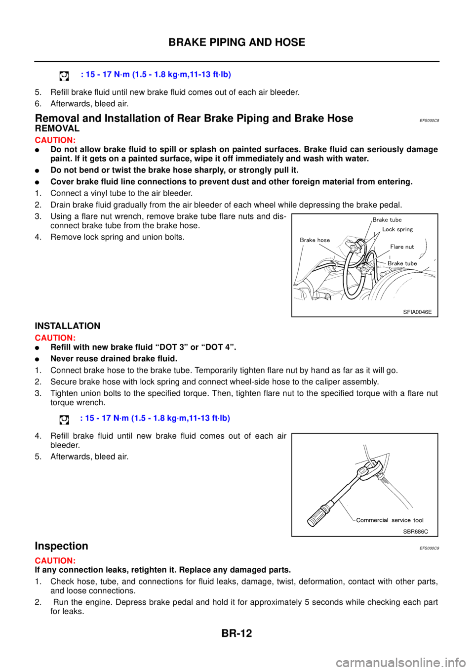
3. Using a flare nut wrench, remove brake tube flare nuts and dis-
connect brake tube from the brake hose.
4. Remove lock spring and union bolts.
INSTALLATION
CAUTION:
lRefill with new brake fluid “DOT 3” or “DOT 4”.
lNever reuse drained brake fluid.
1. Connect brake hose to the brake tube. Temporarily tighten flare nut by hand as far as it will go.
2. Secure brake hose with lock spring and connect wheel-side hose to the caliper assembly.
3. Tighten union bolts to the specified torque. Then, tighten flare nut to the specified torque with a flare nut
torque wrench.
4. Refill brake fluid until new brake fluid comes out of each air
bleeder.
5. Afterwards, bleed air.
InspectionEFS000C9
CAUTION:
If any connection leaks, retighten it. Replace any damaged parts.
1. Check hose, tube, and connections for fluid leaks, damage, twist, deformation, contact with other parts,
and loose connections.
2. Run the engine. Depress brake pedal and hold it for approximately 5 seconds while checking each part
for leaks.:15-17N·m(1.5-1.8kg·m,11-13ft·lb)
SFIA0046E
: 15 - 17 N·m (1.5 - 1.8 kg·m,11-13 ft·lb)
SBR686C
Page 855 of 3066
FRONT DISC BRAKE
BR-21
C
D
E
G
H
I
J
K
L
MA
B
BR
FRONT DISC BRAKEPFP:41000
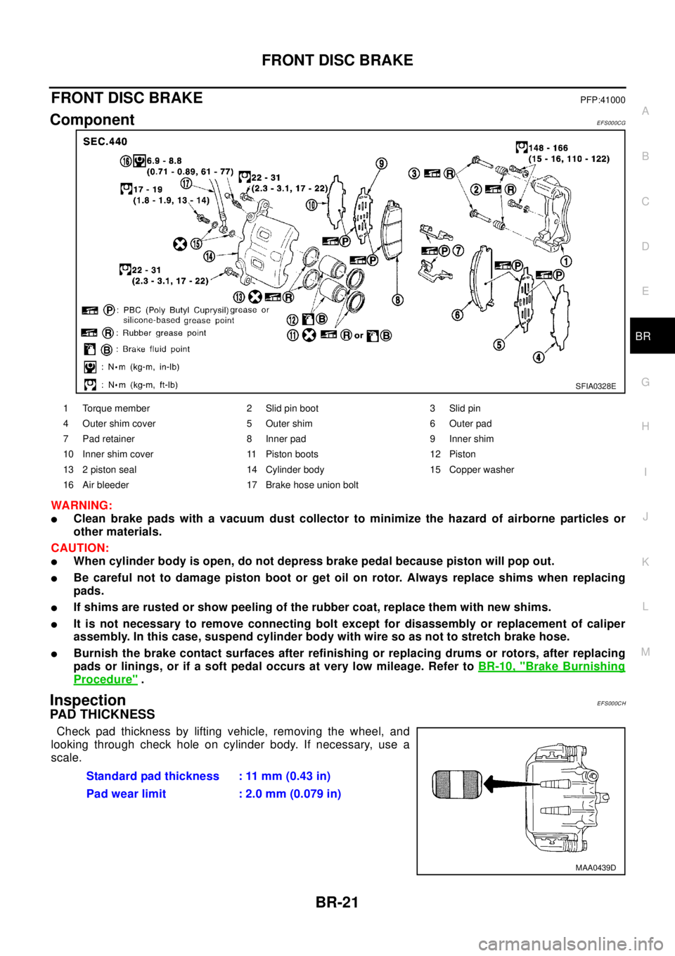
ComponentEFS000CG
WA RN ING:
lClean brake pads with a vacuum dust collector to minimize the hazard of airborne particles or
other materials.
CAUTION:
lWhen cylinder body is open, do not depress brake pedal because piston will pop out.
lBe careful not to damage piston boot or get oil on rotor. Always replace shims when replacing
pads.
lIf shims are rusted or show peeling of the rubber coat, replace them with new shims.
lIt is not necessary to remove connecting bolt except for disassembly or replacement of caliper
assembly. In this case, suspend cylinder body with wire so as not to stretch brake hose.
lBurnish the brake contact surfaces after refinishing or replacing drums or rotors, after replacing
pads or linings, or if a soft pedal occurs at very low mileage. Refer toBR-10, "
Brake Burnishing
Procedure".
InspectionEFS000CH
PAD THICKNESS
Check pad thickness by lifting vehicle, removing the wheel, and
looking through check hole on cylinder body. If necessary, use a
scale.
SFIA0328E
1 Torque member 2 Slid pin boot 3 Slid pin
4 Outer shim cover 5 Outer shim 6 Outer pad
7 Pad retainer 8 Inner pad 9 Inner shim
10 Inner shim cover 11 Piston boots 12 Piston
13 2 piston seal 14 Cylinder body 15 Copper washer
16 Air bleeder 17 Brake hose union bolt
Standard pad thickness : 11 mm (0.43 in)
Pad wear limit : 2.0 mm (0.079 in)
MAA0439D
Page 858 of 3066
BR-24
FRONT DISC BRAKE
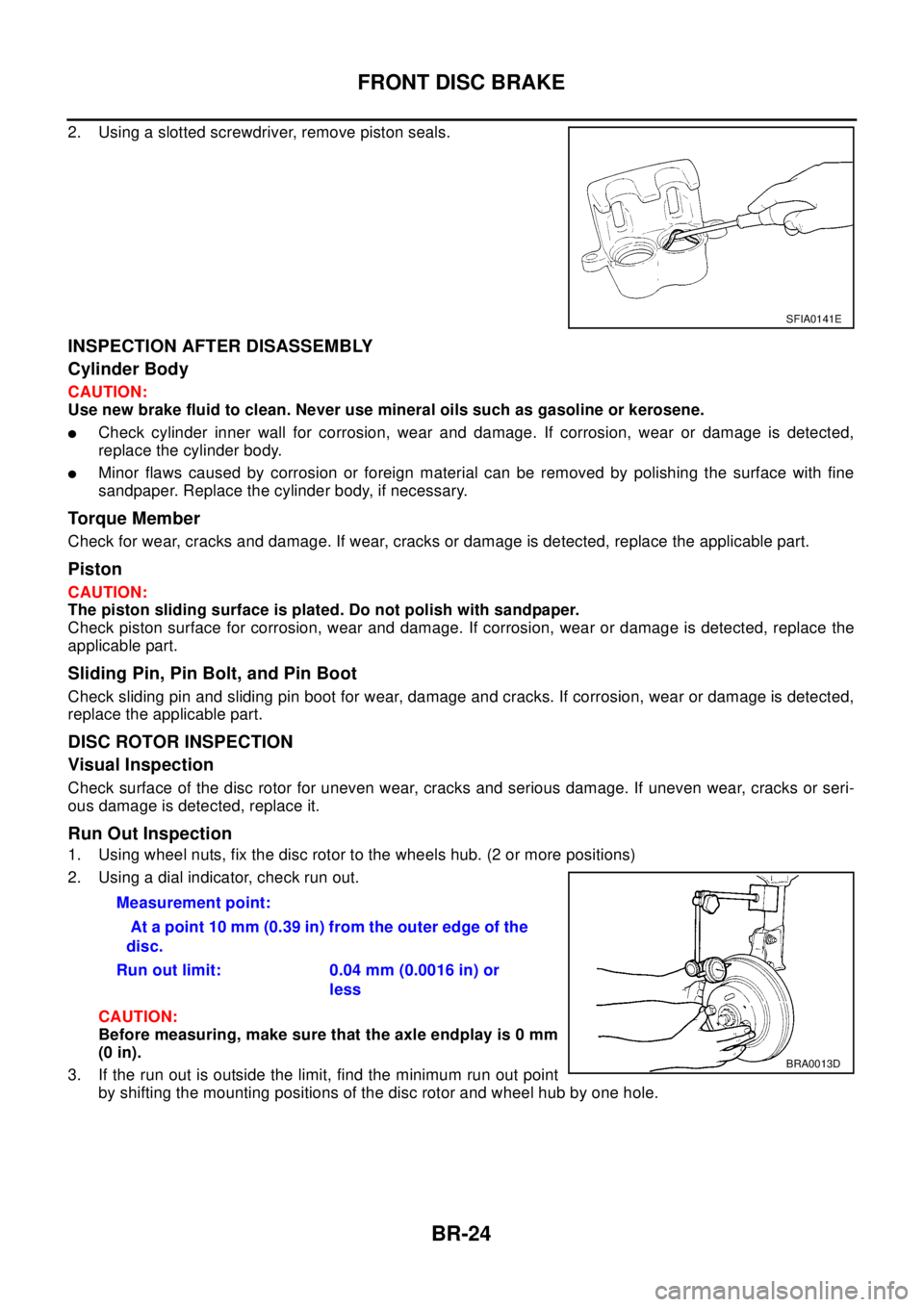
2. Using a slotted screwdriver, remove piston seals.
INSPECTION AFTER DISASSEMBLY
Cylinder Body
CAUTION:
Use new brake fluid to clean. Never use mineral oils such as gasoline or kerosene.
lCheck cylinder inner wall for corrosion, wear and damage. If corrosion, wear or damage is detected,
replace the cylinder body.
lMinor flaws caused by corrosion or foreign material can be removed by polishing the surface with fine
sandpaper. Replace the cylinder body, if necessary.
Torque Member
Check for wear, cracks and damage. If wear, cracks or damage is detected, replace the applicable part.
Piston
CAUTION:
The piston sliding surface is plated. Do not polish with sandpaper.
Check piston surface for corrosion, wear and damage. If corrosion, wear or damage is detected, replace the
applicable part.
Sliding Pin, Pin Bolt, and Pin Boot
Check sliding pin and sliding pin boot for wear, damage and cracks. If corrosion, wear or damage is detected,
replace the applicable part.
DISC ROTOR INSPECTION
Visual Inspection
Check surface of the disc rotor for uneven wear, cracks and serious damage. If uneven wear, cracks or seri-
ous damage is detected, replace it.
Run Out Inspection
1. Using wheel nuts, fix the disc rotor to the wheels hub. (2 or more positions)
2. Using a dial indicator, check run out.
CAUTION:
Before measuring, make sure that the axle endplay is 0 mm
(0 in).
3. If the run out is outside the limit, find the minimum run out point
by shifting the mounting positions of the disc rotor and wheel hub by one hole.
SFIA0141E
Measurement point:
At a point 10 mm (0.39 in) from the outer edge of the
disc.
Run out limit: 0.04 mm (0.0016 in) or
less
BRA0013D
Page 861 of 3066
REAR DISC BRAKE
BR-27
C
D
E
G
H
I
J
K
L
MA
B
BR
REAR DISC BRAKEPFP:44000
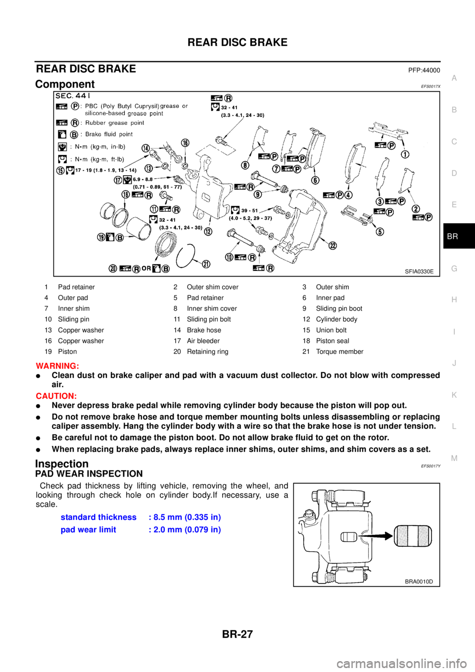
ComponentEFS0017X
WA RN ING:
lClean dust on brake caliper and pad with a vacuum dust collector. Do not blow with compressed
air.
CAUTION:
lNever depress brake pedal while removing cylinder body because the piston will pop out.
lDo not remove brake hose and torque member mounting bolts unless disassembling or replacing
caliper assembly. Hang the cylinder body with a wire so that the brake hose is not under tension.
lBe careful not to damage the piston boot. Do not allow brake fluid to get on the rotor.
lWhen replacing brake pads, always replace inner shims, outer shims, and shim covers as a set.
InspectionEFS0017Y
PAD WEAR INSPECTION
Check pad thickness by lifting vehicle, removing the wheel, and
looking through check hole on cylinder body.If necessary, use a
scale.
SFIA0330E
1 Pad retainer 2 Outer shim cover 3 Outer shim
4 Outer pad 5 Pad retainer 6 Inner pad
7 Inner shim 8 Inner shim cover 9 Sliding pin boot
10 Sliding pin 11 Sliding pin bolt 12 Cylinder body
13 Copper washer 14 Brake hose 15 Union bolt
16 Copper washer 17 Air bleeder 18 Piston seal
19 Piston 20 Retaining ring 21 Torque member
standard thickness : 8.5 mm (0.335 in)
pad wear limit : 2.0 mm (0.079 in)
BRA0010D
Page 864 of 3066
BR-30
REAR DISC BRAKE
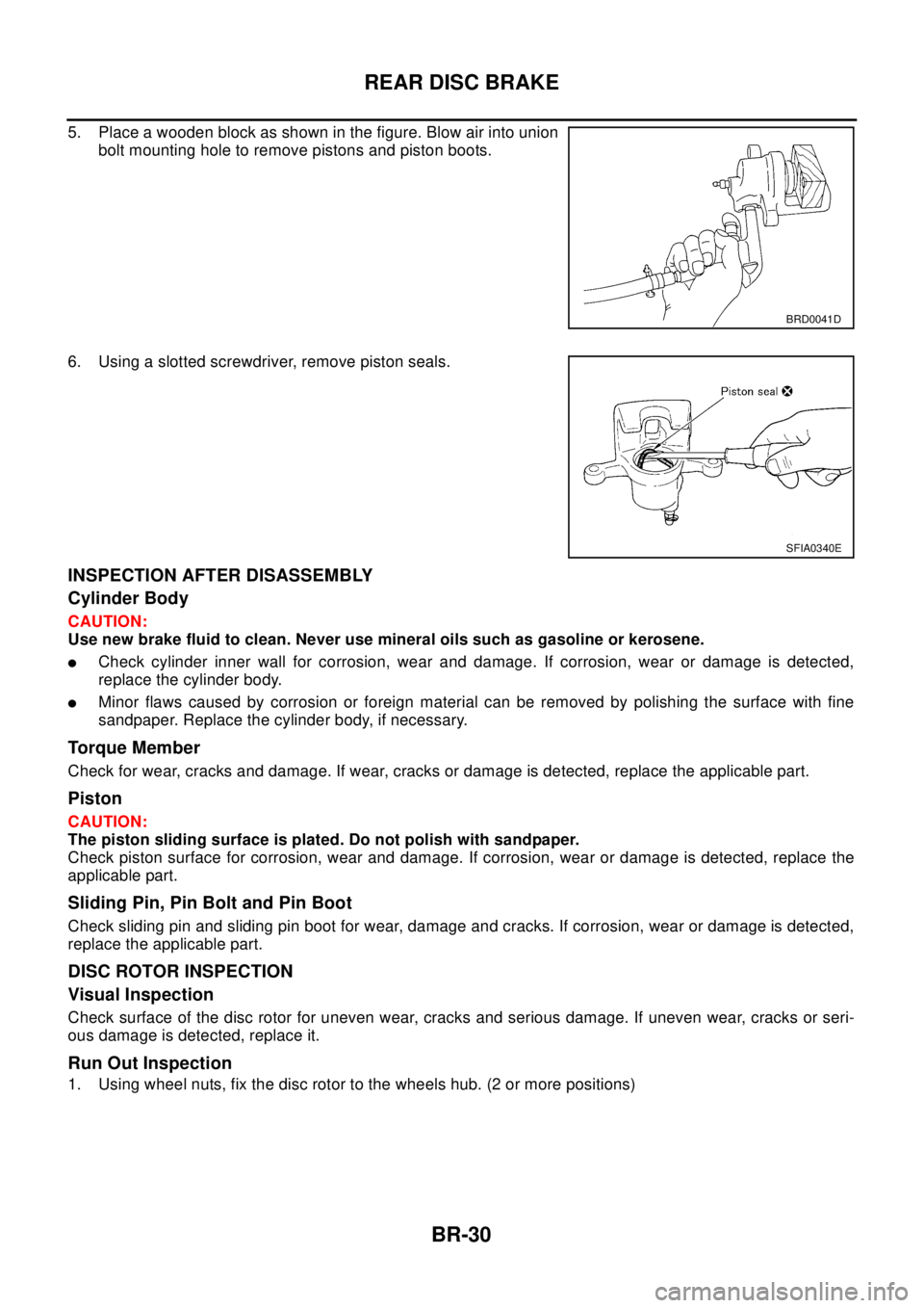
5. Place a wooden block as shown in the figure. Blow air into union
bolt mounting hole to remove pistons and piston boots.
6. Using a slotted screwdriver, remove piston seals.
INSPECTION AFTER DISASSEMBLY
Cylinder Body
CAUTION:
Use new brake fluid to clean. Never use mineral oils such as gasoline or kerosene.
lCheck cylinder inner wall for corrosion, wear and damage. If corrosion, wear or damage is detected,
replace the cylinder body.
lMinor flaws caused by corrosion or foreign material can be removed by polishing the surface with fine
sandpaper. Replace the cylinder body, if necessary.
Torque Member
Check for wear, cracks and damage. If wear, cracks or damage is detected, replace the applicable part.
Piston
CAUTION:
The piston sliding surface is plated. Do not polish with sandpaper.
Check piston surface for corrosion, wear and damage. If corrosion, wear or damage is detected, replace the
applicable part.
Sliding Pin, Pin Bolt and Pin Boot
Check sliding pin and sliding pin boot for wear, damage and cracks. If corrosion, wear or damage is detected,
replace the applicable part.
DISC ROTOR INSPECTION
Visual Inspection
Check surface of the disc rotor for uneven wear, cracks and serious damage. If uneven wear, cracks or seri-
ous damage is detected, replace it.
Run Out Inspection
1. Using wheel nuts, fix the disc rotor to the wheels hub. (2 or more positions)
BRD0041D
SFIA0340E
Page 872 of 3066
![NISSAN X-TRAIL 2003 Electronic Repair Manual BRC-4
[4WD/ABS]
PRECAUTIONS
[4WD/ABS]PRECAUTIONSPFP:00001
Precautions for brake systemEFS001B6
lRecommended fluid is brake fluid “DOT 3 ”or “DOT 4”.
lNever reuse drained brake fluid.
lBe caref NISSAN X-TRAIL 2003 Electronic Repair Manual BRC-4
[4WD/ABS]
PRECAUTIONS
[4WD/ABS]PRECAUTIONSPFP:00001
Precautions for brake systemEFS001B6
lRecommended fluid is brake fluid “DOT 3 ”or “DOT 4”.
lNever reuse drained brake fluid.
lBe caref](/img/5/57402/w960_57402-871.png)
BRC-4
[4WD/ABS]
PRECAUTIONS
[4WD/ABS]PRECAUTIONSPFP:00001
Precautions for brake systemEFS001B6
lRecommended fluid is brake fluid “DOT 3 ”or “DOT 4”.
lNever reuse drained brake fluid.
lBe careful not to splash brake fluid on painted areas.
lTo clean or wash all parts of master cylinder, disc brake caliper and wheel cylinder, use clean brake fluid.
lNever use mineral oils such as gasoline or kerosene. They will ruin rubber parts of the hydraulic system.
lUse flare nut wrench when removing and installing brake tube.
lAlways torque brake lines when installing.
lBurnish the brake contact surfaces after refinishing or replacing
drums or rotors, after replacing pads or linings, or if a soft pedal
occurs at very low mileage. Refer toBR-10, "
Brake Burnishing
Procedure".
lBefore working, turn OFF ignition switch. Disconnect connectors
for ABS actuator and control module or battery terminals.
WAR NIN G:
lClean brake pads and shoes with a waste cloth, then wipe
with a dust collector.
Precautions for brake controlEFS001B7
lIf malfunction is indicated by 4WD warning lamp and/or ABS warning lamp, collect necessary information
from customer (what symptoms are present under what conditions). Find out possible causes before start-
ing service. Besides electrical system inspection, check operation of ABS actuator.
lIf malfunction is detected, proceed to trouble diagnosis after checking tire pressure and tire wear.
lStopping distance or steering stability may be deteriorated by the following conditions. Tire size and type
are in improper combination. Brake pads are not Nissan genuine parts.
lFitting tires of different size on vehicle can be cause of longitudinal vibration. Always use tires of the same
size and brand. Exchange front and rear tires on the following conditions: Longitudinal vibration occurs in
vehicle with tires of the same size and brand. After replacement, perform trouble diagnosis. 1580|None
l4WD/ABS function may have a failure or error under following condition: There is radio, antenna, or
antenna lead-in wire (including wiring) near control module.
lIf aftermarket parts (e.g. Car stereo equipment, CD player) have been installed, check electrical har-
nesses for pinches, open, and improper wiring.
SBR686C
Page 900 of 3066
![NISSAN X-TRAIL 2003 Electronic Repair Manual BRC-32
[4WD/ABS]
TROUBLE DIAGNOSIS
4WDSOLENOIDVALVE
lDisconnect connector and measure resistance between termi-
nals B152 No. 1 (L/W) and No. 2 (LG).
Basic InspectionEFS001BK
BASIC INSPECTION 1 BRAKE NISSAN X-TRAIL 2003 Electronic Repair Manual BRC-32
[4WD/ABS]
TROUBLE DIAGNOSIS
4WDSOLENOIDVALVE
lDisconnect connector and measure resistance between termi-
nals B152 No. 1 (L/W) and No. 2 (LG).
Basic InspectionEFS001BK
BASIC INSPECTION 1 BRAKE](/img/5/57402/w960_57402-899.png)
BRC-32
[4WD/ABS]
TROUBLE DIAGNOSIS
4WDSOLENOIDVALVE
lDisconnect connector and measure resistance between termi-
nals B152 No. 1 (L/W) and No. 2 (LG).
Basic InspectionEFS001BK
BASIC INSPECTION 1 BRAKE FLUID LEVEL AND LEAKAGE INSPECTION
1. Check fluid level in brake reservoir tank. If fluid level is low, refill brake fluid.
2. Check area around brake piping and ABS actuator for leaks. If a leak or oozing is detected, check as fol-
lows:
lIf connections at ABS actuator are loose, tighten piping to the specified torque. Then check again for
leaks, and be sure there is no fluid leak.
lIf the flare nuts at the connections and the threads of the ABS actuator are damaged, replace the dam-
aged parts. Then check again for leaks, and make sure that there is no fluid leak.
lIf leak or oozing is detected except for ABS actuator connections, wipe it with clean cloth. Then check
again for leaks. If there is still leak or oozing, replace damaged part.
lIf leak or oozing is detected on ABS actuator, wipe with a clean cloth. Check again for leaks, and if
there is still leak or oozing, replace ABS actuator.
CAUTION:
ABS actuator body cannot be disassembled.
BASIC INSPECTION 2 INSPECTION FOR LOOSE POWER SUPPLY TERMINAL
Check battery for looseness on battery positive/negative terminals and ground connection.
BASIC INSPECTION 3 ABS/4WD WARNING LAMP INSPECTION
1. Be sure ABS warning lamp turns on when ignition switch is turned ON. If it does not turn on, check ABS
warning lamp harness.
2. Check 4WD warning lamp illuminates with ignition switch ON. If not so, check 4WD warning lamp path.
3. Be sure ABS warning lamp turns off after approximately 1 second when ignition switch is turned ON. If it
does not turn off, perform self-diagnosis.
4. Be sure 4WD warning lamp turns off after several seconds when engine is started. If it does not turn off,
perform self-diagnosis.
5. After driving the vehicle at Approx. 30km/h for a few seconds, check 4WD warning lamp and ABS warning
lamp do not illuminate.
6. After completing the self-diagnosis, always erase the diagnosis memory.
Wheel Speed Sensor SystemEFS001BL
INSPECTION PROCEDURE
1.TIRE INSPECTION
Check air pressure, wear, and size.
Are air pressure, wear, and size within specifications?
YES >> GO TO 2.
NO >> Adjust air pressure, or replace tire.4WD solenoid valve 1 - 2 : Approx. 2.45W
SDIA0136E