sensor OLDSMOBILE SILHOUETTE 1997 Owners Manual
[x] Cancel search | Manufacturer: OLDSMOBILE, Model Year: 1997, Model line: SILHOUETTE, Model: OLDSMOBILE SILHOUETTE 1997Pages: 436, PDF Size: 21.87 MB
Page 56 of 436
Your vehicle is equipped with a crash sensing and
diagnostic module, which records information about
the air bag system. The module records information
about the readiness of the system, when the sensors are
activated and driver’s safety belt usage at deployment.
Let only qualified technicians work on your air bag
system. Improper service can mean that your air bag
system won’t work properly. See your retailer
for service.
NOTICE:
If you damage the cover for the driver’s or the
right front passenger’s air bag, the bag may not
work properly. You may have to replace the air
bag module in the steering wheel or both the air
bag module and the instrument panel for the
passenger’s air bag.
Do not open or break the air
bag covers.
Servicing Your Air Bag-Equipped
Oldsmobile
Air bags affect how your Oldsmobile should be
serviced. There are parts of the air bag system in several
places around your vehicle. You don’t want the system
to inflate while someone is working on your vehicle.
Your Oldsmobile retailer and the Silhouette Service
Manual have information about servicing your vehicle
and the air bag system. To purchase
a service manual,
see “Service and Owner Publications” in the Index.
For up to 10 minutes after the ignition key is
turned off and the battery is disconnected, an air
bag can still inflate during improper service. You
can be injured
if you are close to an air bag when
it inflates. Avoid yellow connectors. They are
probably part of the air bag system. Be sure
to
follow proper service procedures, and make sure
the person performing work for you is qualified
to
do so.
The air bag system does not need regular maintenance.
1-48
ProCarManuals.com
Page 122 of 436
NOTICE:
If your vehicle seems to start up rather slowly,
or if it seems not to shift gears as you go faster,
something may be wrong with
a transaxle system
sensor.
If you drive very far that way, your
vehicle can be damaged.
So, if this happens,
have your vehicle serviced right
away. Until then,
you can use SECOND
(2) when you are driving
less than
35 mph (55 kmh) and THIRD (3) for
higher speeds.
FIRST (1): This position gives you even more power
(but lower fuel economy) than
SECOND (2). You can
use it on very steep hills, or in deep snow or mud. If
the selector lever is put in FIRST (I), the transaxle
won’t downshift into first gear
until the vehicle is
going
slow enough.
NOTICE:
If your front wheels can’t rotate, don’t try to
drive. This might happen if you were stuck in
very deep sand or mud or were up against
a
solid object. You could damage your transaxle.
Also, if you stop when going uphill, don’t hold
your vehicle there with only the accelerator
pedal. This could overheat and damage the
transaxle.
Use your brakes or shift into PARK (P)
to hold your vehicle in position on a hill.
2-34
ProCarManuals.com
Page 148 of 436
A light sensor on top of the instrument panel makes the
DRL work, so be sure it isn’t covered. The DRL system
will make your front parWturn signal lamps come
on in
daylight when:
The ignition is on,
the headlamp switch is off, and
the parking brake is released.
When the
DRL are on, only your front park/turn signal
lamps will be on. Your instrument panel won’t be
lit up.
When it’s dark enough outside, the exterior lamps will
come on automatically. When it’s bright enough outside,
the exterior lamps will go
out and the DRL will turn on.
Of course, you may still turn on the headlamps any time
you need to.
To idle your vehicle with the DRL or exterior lamps off,
set the parking brake while the ignition is
in the OFF or
LOCK position. Then start the vehicle. The DRL will
stay off until you release
the parking brake,
As with any vehicle, you should turn on the regular
headlamp system when you need
it.
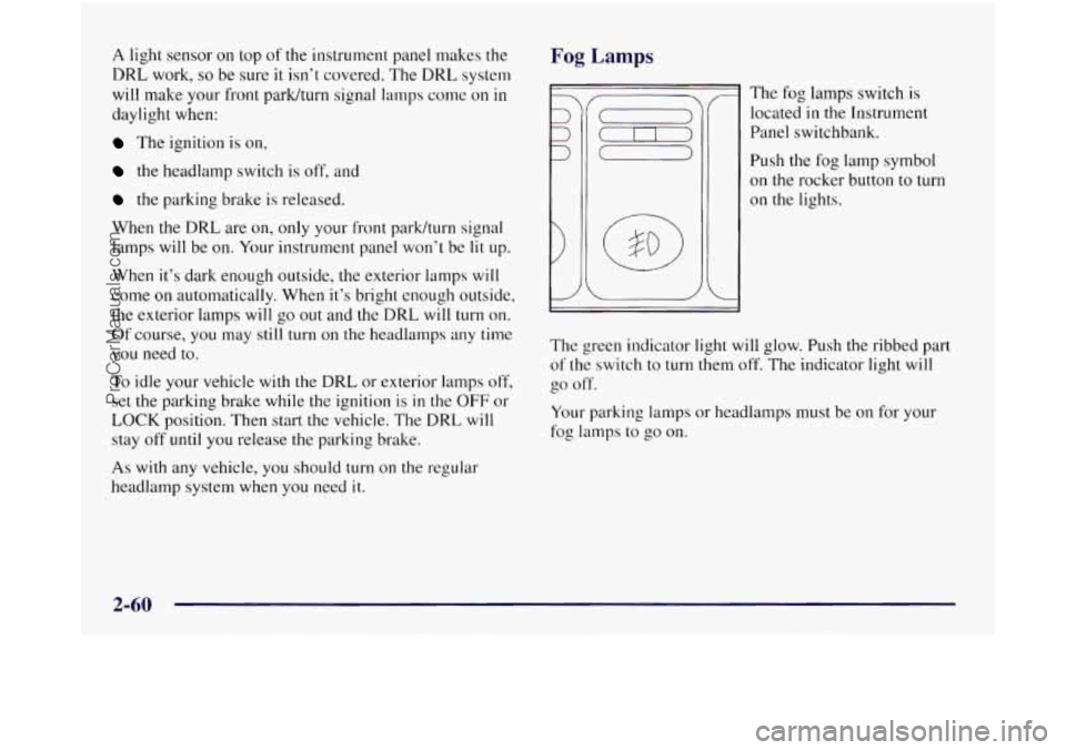
Fog Lamps
r
v-
I The fog lamps switch is
located
in the Instrument
Panel switchbank.
Push the fog
on the rockel
on the lights. lamp symbol
- button to
turn
I J
The green indicator light will glow. Push the ribbed part
of the switch to turn them off. The indicator light will
go off.
Your parking lamps or headlamps must be on for your
fog lamps to go on.
2-60
ProCarManuals.com
Page 161 of 436
Automatic Compass Calibration
The compass is self-calibrating which eliminates the
need to manually set the compass. When the vehicle is
new,
the calibration process may not be complete. In
these cases the calibration symbol, C, will be displayed
where
the compass reading is normally displayed.
To calibrate the compass: In an area free from large metal
objects, make three
360" turns. The calibration symbol
will turn
off and the compass reading will be displayed.
Manual Compass Calibration
If the compass appears erratic and the calibration
symbol does not appear, you must manually put
the
compass into the calibration mode.
Turn the ignition on and cycle the DIC to the
CompadTernperature mode. Press both the E/M and
MODE buttons for at least
10 seconds until the
calibration symbol appears. Release both buttons and
complete three
360" turns in an area free from large
metal objects.
The calibration symbol will turn off and
the compass reading will be displayed.
Error Displays
An error of the vehicle's speed sensor or fuel sender
0 In the absence of vehicle communications, a double
will
cause
-E- to be displayed.
dash,
--, is displayed.
Trip Computer
There are five trip computer displays which may be
stepped through by pushing the MODE button. The
information will appear
in the following order:
0
0
0
0
0
Average Fuel Economy (AVG ECON) - This shows
the average fuel economy since the last reset.
Instantaneous Fuel Economy (INST ECON)
- This
shows fuel economy for the most recent second
of driving.
Trip Range (RANGE)
- This shows the estimated
distance that can be traveled with the remaining fuel.
The fuel economy used to calculate range is based on
the last few hours
of driving.
Trip Fuel Used (FUEL USED)
- This shows the
accumulated fuel used since the last reset.
Average Speed (AVG
SPEED) - This shows the
average speed since the last reset.
Resetting the Trip Computer
Press and hold the MODE and E/M buttons for at least
two seconds. The reset
is acknowledged with the display
showing all segments on for a period of half
a second. A
reset can only be done
in AVG ECON, FUEL USED
and AVG
SPEED displays. Resetting affects all three
displays regardless of what display you are in.
ProCarManuals.com
Page 182 of 436
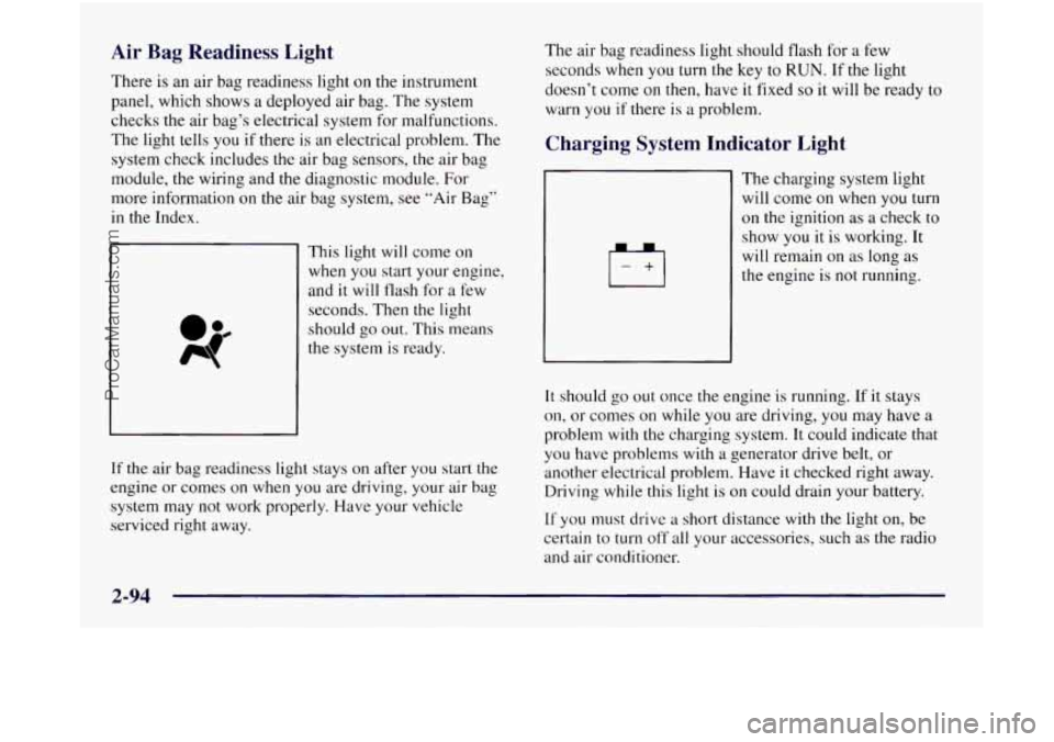
Air Bag Readiness Light
There is an air bag readiness light on the instrument
panel, which shows a deployed air bag. The system
checks the air bag’s electrical system for malfunctions.
The light tells you if there is an electrical problem. The
system check includes
the air bag sensors, the air bag
module, the wiring and the diagnostic module. For
more information on the air bag system, see “Air Bag”
in the Index.
This light will come on
when you start your engine,
and it will tlash for a few
seconds. Then the light
should
go out. This means
the system
is ready.
If
the air bag readiness light stays on after you start the
engine or comes
on when you are driving, your air bag
system may not work properly. Have your vehicle
serviced right away. The air
bag readiness light should flash for a few
seconds when you turn the key to
RUN. If the light
doesn’t come on then, have
it fixed so it will be ready to
warn you if there is a problem.
Charging System Indicator Light
1+1
The charging system light
will come on when you turn
on the ignition as a check to
show you it is working. It
will remain on as long as
the engine is
not running.
It should go out once the engine is running. If it stays
on, or comes on while you are driving, you may have a
problem with the charging system. It could indicate that
you have problems with a generator drive belt, or
another electrical problem. Have
it checked right away.
Driving while this light is on could drain your battery.
If you must drive a short distance with the light on, be
certain to turn
off all your accessories, such as the radio
and air conditioner.
ProCarManuals.com
Page 357 of 436
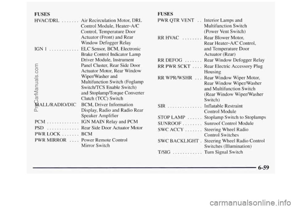
FUSES
HVAC/DRL ....... Air Recirculation Motor, DRL
IGN
1 ...........
MALL/RADIO/DIC Control Module, Heater-A/C
Control,
Temperature Door
Actuator (Front) and Rear
Window Defogger Relay
ELC Sensor, BCM, Electronic
Brake Control Indicator Lamp
Driver Module, Instrument
Panel Cluster, Rear Side Door
Actuator Motor, Rear Window
Wiperwasher and
Multifunction Switch (Foglamp
Switch/TCS Enable Switch)
and Stoplamp/Torque Converter
Clutch (TCC) Switch
BCM, Driver Information
Display, Radio and Radio Rear
Speaker Amplifier
PCM
............. IGN MAIN Relay and PCM
PSD
............. Rear Side Door Actuator Motor
PWR LOCK
....... BCM
PWR MIRROR
.... Power Remote Control
Mirror Switch
FUSES
PWR QTR VENT . . Interior Lamps and
Multifunction Switch
(Power
Vent Switch)
RR HVAC ........ Rear Blower Motor,
Rear Heater-A/C Control,
and Temperature Door
Actuator (Rear)
RR
DEFOG ....... Rear Window Defogger Relay
RR PWR SCKT .... Rear Electric Accessory Plug
Housing
Rear Window Wiper/Washer
and Multifunction Switch
(Rear Window Wiper/Washer
Switch)
Control Module
RR WPR/WSHR
... Rear Window Wiper Motor,
SIR
.............. Inflatable Restraint
STOP LAMP ...... Stoplamp Switch to Stoplamps
SUNROOF
........ Sunroof Control Module
SWC ACCY
....... Steering Wheel Radio
SWC BACKLIGHT
. Steering Wheel Radio Control
T/SIG ............ Turn Signal Switch
Control
Switches
Switches (Illumination)
6-59
ProCarManuals.com
Page 359 of 436
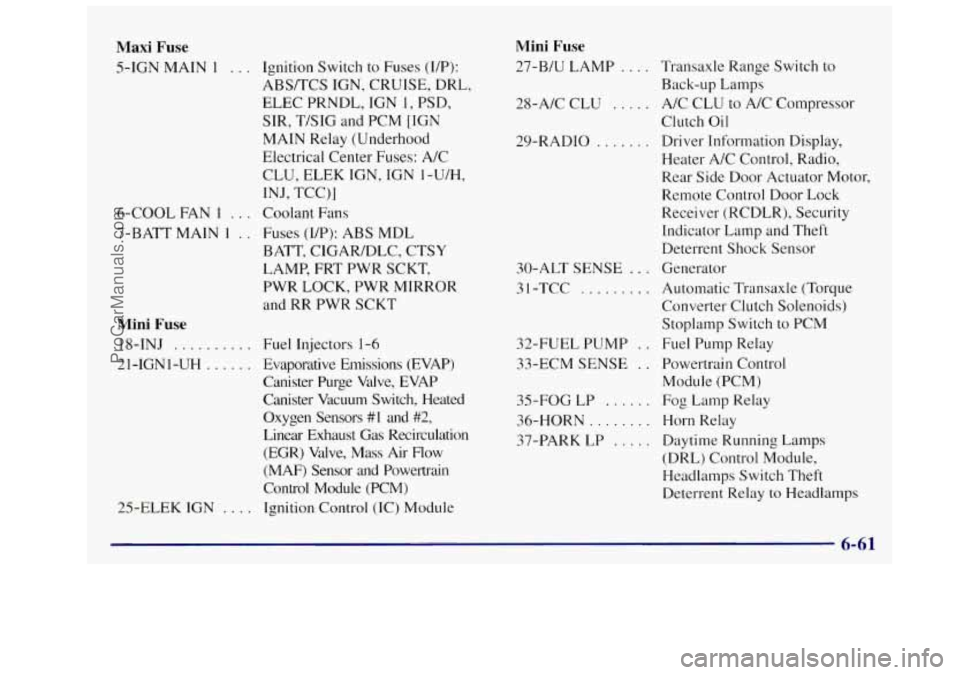
Maxi Fuse
5-IGN MAIN 1 . . . Ignition Switch to Fuses (UP):
ABS/TCS IGN, CRUISE, DRL,
ELEC PRNDL, IGN
1, PSD,
SIR, T/SIG and PCM [IGN
MAIN Relay (Underhood
Electrical Center Fuses: A/C
INJ, TCC)]
CLU,
ELEK
IGN, IGN 1-U/H,
6-COOL FAN
I . . . Coolant Fans
7-BATT MAIN
1 . . Fuses (IP): ABS MDL
BATT, CIGARIDLC, CTSY
LAMP, FRT PWR SCKT,
PWR LOCK, PWR MIRROR
and RR PWR SCKT
Mini Fuse
18-INJ . . . . . . . . . .
21-IGNI-UH . . . . . .
25-ELEK IGN . . .
Fuel Injectors 1-6
Evaporative Emissions (EVAP)
Canister Purge Valve, EVAP
Canister Vacuum Switch, Heated
Oxygen Sensors
#1 and #2,
Linear Exhaust Gas Recirculation
(EGR) Valve, Mass Air Flow
(MAF) Sensor and Powertrain
Control Module (PCM)
Ignition Control (IC) Module
Mini Fuse
27-B/U LAMP . . . . Transaxle Range Switch to
Back-up Lamps
28-A/C CLU
, . . . . A/C CLU to A/C Compressor
Clutch
Oil
29-RADIO . . . . . , , Driver Information Display,
Heater A/C Control, Radio,
Rear Side Door Actuator Motor,
Remote Control Door Lock
Receiver (RCDLR), Security
Indicator Lamp and Theft
Deterrent Shock Sensor
30-ALT SENSE
. . . Generator
3
1 -TCC . . . . . . . . . Automatic Transaxle (Torque
Converter Clutch Solenoids)
Stoplamp Switch to PCM
32-FUEL PUMP
. . Fuel Pump Relay
33-ECM SENSE
. . Powertrain Control
35-FOG
LP . . . . . . Fog Lamp Relay
36-HORN
. . . . . . . . Horn Relay
37-PARK LP
. . . . . Daytime Running Lamps
(DRL) Control Module,
Headlamps Switch Theft
Deterrent Relay to Headlamps
Module
(PCM)
6-61
ProCarManuals.com