ECU OPEL CALIBRA 1988 Service Owner's Manual
[x] Cancel search | Manufacturer: OPEL, Model Year: 1988, Model line: CALIBRA, Model: OPEL CALIBRA 1988Pages: 525, PDF Size: 58.26 MB
Page 27 of 525
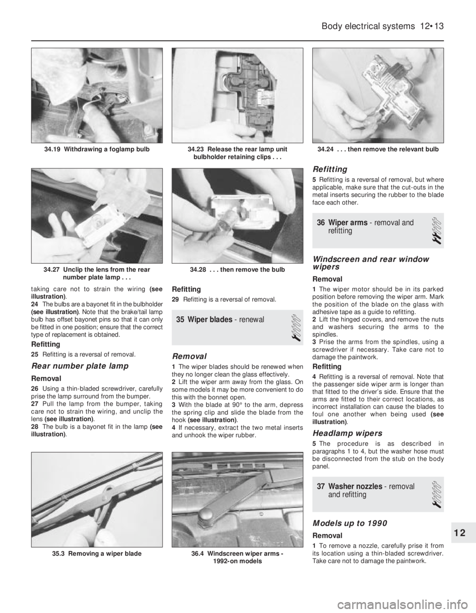
taking care not to strain the wiring (see
illustration).
24The bulbs are a bayonet fit in the bulbholder
(see illustration). Note that the brake/tail lamp
bulb has offset bayonet pins so that it can only
be fitted in one position; ensure that the correct
type of replacement is obtained.
Refitting
25Refitting is a reversal of removal.
Rear number plate lamp
Removal
26Using a thin-bladed screwdriver, carefully
prise the lamp surround from the bumper.
27Pull the lamp from the bumper, taking
care not to strain the wiring, and unclip the
lens (see illustration).
28The bulb is a bayonet fit in the lamp (see
illustration).
Refitting
29Refitting is a reversal of removal.
35Wiper blades -renewal
1
Removal
1The wiper blades should be renewed when
they no longer clean the glass effectively.
2Lift the wiper arm away from the glass. On
some models it may be more convenient to do
this with the bonnet open.
3With the blade at 90°to the arm, depress
the spring clip and slide the blade from the
hook (see illustration).
4If necessary, extract the two metal inserts
and unhook the wiper rubber.
Refitting
5Refitting is a reversal of removal, but where
applicable, make sure that the cut-outs in the
metal inserts securing the rubber to the blade
face each other.
36Wiper arms - removal and
refitting
2
Windscreen and rear window
wipers
Removal
1The wiper motor should be in its parked
position before removing the wiper arm. Mark
the position of the blade on the glass with
adhesive tape as a guide to refitting.
2Lift the hinged covers, and remove the nuts
and washers securing the arms to the
spindles.
3Prise the arms from the spindles, using a
screwdriver if necessary. Take care not to
damage the paintwork.
Refitting
4Refitting is a reversal of removal. Note that
the passenger side wiper arm is longer than
that fitted to the driver’s side. Ensure that the
arms are fitted to their correct locations, as
incorrect installation can cause the blades to
foul one another when being used (see
illustration).
Headlamp wipers
5The procedure is as described in
paragraphs 1 to 4, but the washer hose must
be disconnected from the stub on the body
panel.
37Washer nozzles - removal
and refitting
1
Models up to 1990
Removal
1To remove a nozzle, carefully prise it from
its location using a thin-bladed screwdriver.
Take care not to damage the paintwork.
Body electrical systems 12•13
34.24 . . . then remove the relevant bulb
36.4 Windscreen wiper arms -
1992-on models35.3 Removing a wiper blade
34.28 . . . then remove the bulb34.27 Unclip the lens from the rear
number plate lamp . . .
34.23 Release the rear lamp unit
bulbholder retaining clips . . .34.19 Withdrawing a foglamp bulb
12
Page 28 of 525
2Disconnect the washer hose and withdraw
the nozzle.
Refitting
3To refit, reconnect the washer hose to the
nozzle, and push the nozzle into its locating
hole.
4The nozzles can be adjusted by inserting a
pin into the jet, and swivelling it to the
required position.
1991-on models
5The nozzles on all later models are fitted
with twin jets.
6On some later models, the nozzles are
heated; the circuit is fed through fuse 29 and
is live whenever the ignition is switched on.
Current is regulated by a Positive
Temperature Coefficient (PTC) resistor that
takes outside temperature into account.
38Windscreen wiper motor and
linkage - removal and refitting
3
Removal
1Disconnect the battery negative lead.
2Remove the wiper arms, as described in
Section 36.
3Remove the windscreen cowl panel, as
described in Chapter 11.
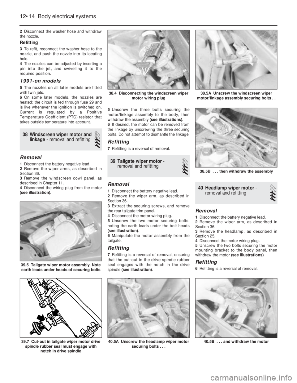
4Disconnect the wiring plug from the motor
(see illustration). 5Unscrew the three bolts securing the
motor/linkage assembly to the body, then
withdraw the assembly (see illustrations).
6If desired, the motor can be removed from
the linkage by unscrewing the three securing
bolts. Do not attempt to dismantle the linkage.
Refitting
7Refitting is a reversal of removal.
39Tailgate wiper motor -
removal and refitting
3
Removal
1Disconnect the battery negative lead.
2Remove the wiper arm, as described in
Section 36.
3Extract the securing screws, and remove
the rear tailgate trim panel.
4Disconnect the motor wiring plug.
5Unscrew the two motor securing bolts,
noting the earth leads under the bolt heads
(see illustration).
6Manipulate the motor assembly from the
tailgate.
Refitting
7Refitting is a reversal of removal, ensuring
that the cut-out in the drive spindle rubber
seal engages with the notch in the drive
spindle (see illustration).
40Headlamp wiper motor -
removal and refitting
3
Removal
1Disconnect the battery negative lead.
2Remove the wiper arm, as described in
Section 36.
3Remove the headlamp, as described in
Section 25.
4Disconnect the motor wiring plug.
5Unscrew the two bolts securing the motor
mounting bracket to the body panel, then
withdraw the motor (see illustrations).
Refitting
6Refitting is a reversal of removal.
12•14Body electrical systems
38.4 Disconnecting the windscreen wiper
motor wiring plug
38.5B . . . then withdraw the assembly
40.5B . . . and withdraw the motor40.5A Unscrew the headlamp wiper motor
securing bolts . . .39.7 Cut-out in tailgate wiper motor drive
spindle rubber seal must engage with
notch in drive spindle
39.5 Tailgate wiper motor assembly. Note
earth leads under heads of securing bolts
38.5A Unscrew the windscreen wiper
motor/linkage assembly securing bolts . .
Page 29 of 525
41Washer fluid reservoir -
removal and refitting
2
1Disconnect the battery negative lead.
Models without headlamp wash
Removal
2Disconnect the wiring from the washer
pump.
3Disconnect the washer fluid hose from the
pump. Be prepared for fluid spillage.
4Remove the screw(s) securing the reservoir
to the body, and withdraw the reservoir.
Refitting
5Refitting is a reversal of removal.
Models with headlamp wash
Removal
6On models with headlamp wash, the
reservoir is in two sections, the upper section,
which can be removed from the engine
compartment, and the lower section, which
must be removed from under the wheel arch.
7Disconnect the wiring from the headlamp
wash non-return valve in the top of the
reservoir.
8Disconnect the washer fluid hoses from the
non-return valve. Be prepared for fluid spillage.
9Remove the screw securing the upper
section of the reservoir to the wing panel.
10Loosen the plastic collar securing the
upper section of the reservoir to the lower
section, then withdraw the upper section of
the reservoir from the engine compartment.
11To remove the lower section of the
reservoir, continue as follows.
12Apply the handbrake, then jack up the
front of the vehicle, and support on axle
stands (see “Jacking and Vehicle Support”)
positioned under the body side members.
13Remove the securing screws, and
withdraw the plastic cover from thebumper/front wing to expose the lower
section of the reservoir.
14Remove the horns, (Section 22).
15Remove the wheel arch liner, (Chapter 11).
16Disconnect the wiring and the fluid hoses
from the washer pump. Be prepared for fluid
spillage.
17Unscrew the bolts securing the
horn/reservoir support bracket and the
reservoir to the body, then withdraw the
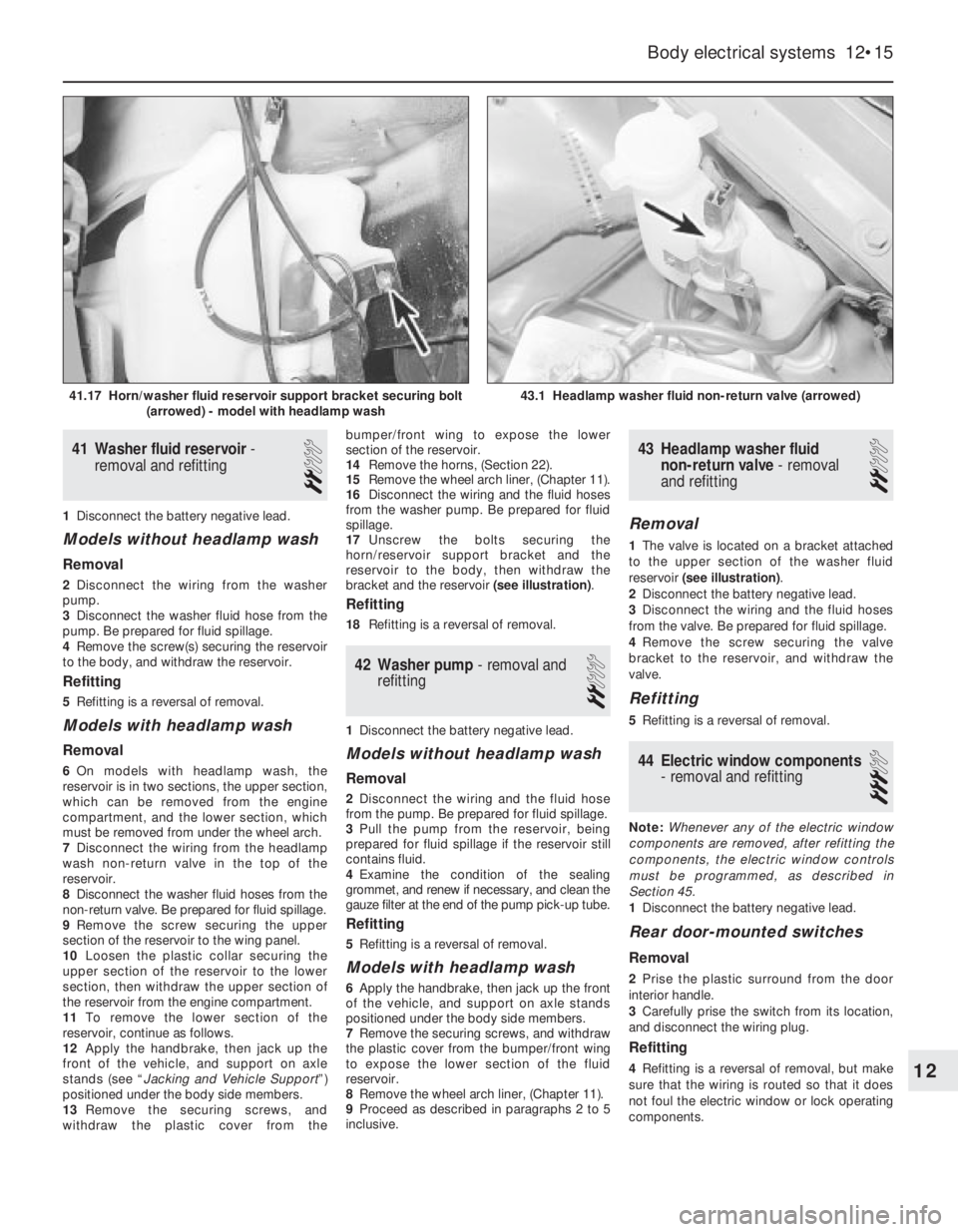
bracket and the reservoir (see illustration).
Refitting
18Refitting is a reversal of removal.
42Washer pump -removal and
refitting
2
1Disconnect the battery negative lead.
Models without headlamp wash
Removal
2Disconnect the wiring and the fluid hose
from the pump. Be prepared for fluid spillage.
3Pull the pump from the reservoir, being
prepared for fluid spillage if the reservoir still
contains fluid.
4Examine the condition of the sealing
grommet, and renew if necessary, and clean the
gauze filter at the end of the pump pick-up tube.
Refitting
5Refitting is a reversal of removal.
Models with headlamp wash
6Apply the handbrake, then jack up the front
of the vehicle, and support on axle stands
positioned under the body side members.
7Remove the securing screws, and withdraw
the plastic cover from the bumper/front wing
to expose the lower section of the fluid
reservoir.
8Remove the wheel arch liner, (Chapter 11).
9Proceed as described in paragraphs 2 to 5
inclusive.
43Headlamp washer fluid
non-return valve -removal
and refitting
2
Removal
1The valve is located on a bracket attached
to the upper section of the washer fluid
reservoir (see illustration).
2Disconnect the battery negative lead.
3Disconnect the wiring and the fluid hoses
from the valve. Be prepared for fluid spillage.
4Remove the screw securing the valve
bracket to the reservoir, and withdraw the
valve.
Refitting
5Refitting is a reversal of removal.
44Electric window components
- removal and refitting
3
Note: Whenever any of the electric window
components are removed, after refitting the
components, the electric window controls
must be programmed, as described in
Section 45.
1Disconnect the battery negative lead.
Rear door-mounted switches
Removal
2Prise the plastic surround from the door
interior handle.
3Carefully prise the switch from its location,
and disconnect the wiring plug.
Refitting
4Refitting is a reversal of removal, but make
sure that the wiring is routed so that it does
not foul the electric window or lock operating
components.
Body electrical systems 12•15
43.1 Headlamp washer fluid non-return valve (arrowed)41.17 Horn/washer fluid reservoir support bracket securing bolt
(arrowed) - model with headlamp wash
12
Page 30 of 525
Centre console-mounted
switches
Removal
5The switches must be removed as a
complete assembly, and cannot be
dismantled. If one of the switches is faulty, the
complete assembly must be renewed.
6Remove the rear section of the centre
console, as described in Chapter 11.
7Release the securing clips, and withdraw
the switch assembly through the top of the
centre console.
Refitting
8Refitting is a reversal of removal.
Operating motors
9Remove the door window regulator, as
described in Chapter 11.
10To remove the motor assembly from the
front door window regulator, unscrew the
three motor securing nuts, and the single
screw securing the pulse pick-up unit to the
regulator assembly. Withdraw the motor,
complete with the pulse pick-up unit. Note
that if the motor or pick-up unit is/are faulty,
the two components must be renewed as an
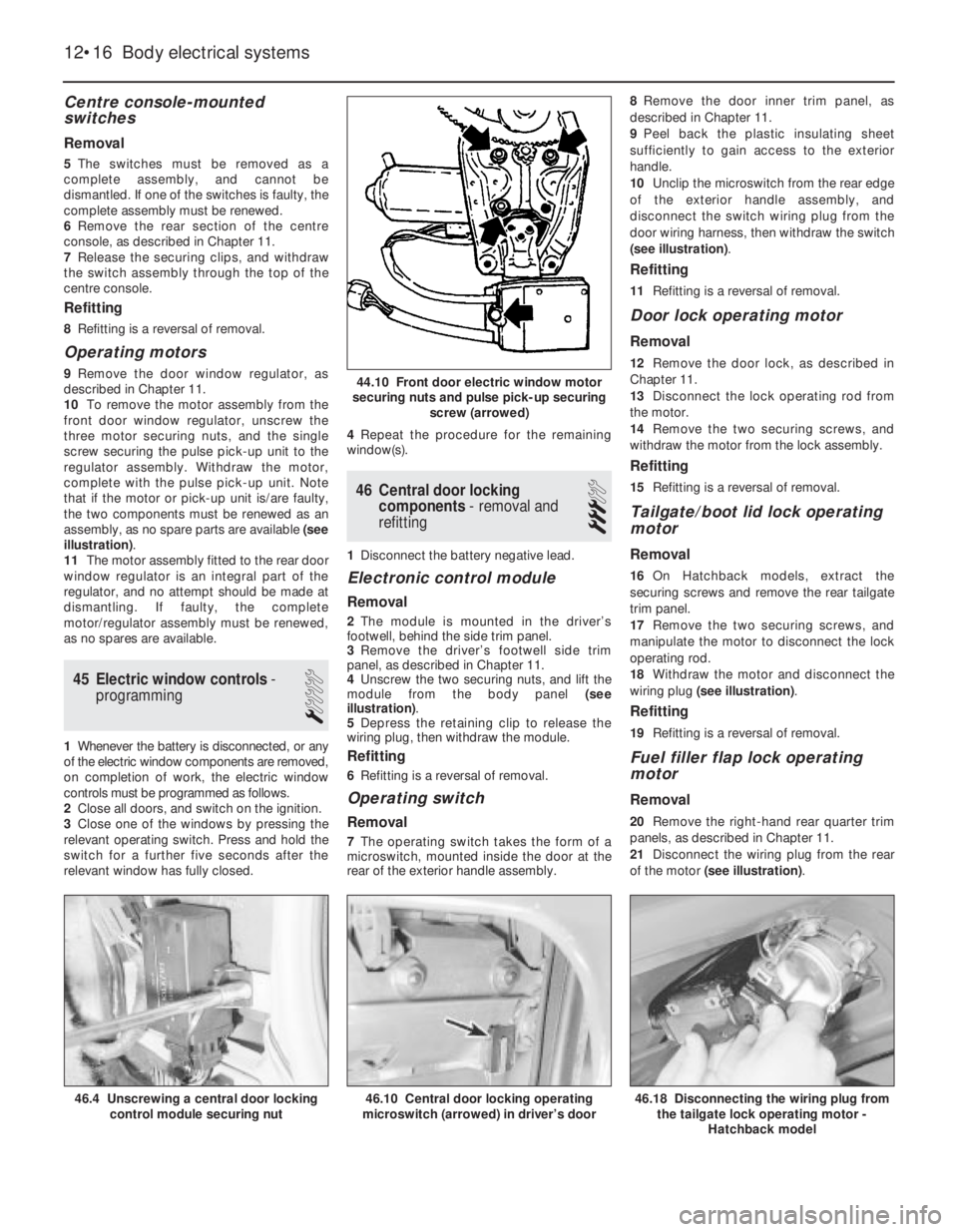
assembly, as no spare parts are available (see
illustration).
11The motor assembly fitted to the rear door
window regulator is an integral part of the
regulator, and no attempt should be made at
dismantling. If faulty, the complete
motor/regulator assembly must be renewed,
as no spares are available.
45Electric window controls -
programming
1
1Whenever the battery is disconnected, or any
of the electric window components are removed,
on completion of work, the electric window
controls must be programmed as follows.
2Close all doors, and switch on the ignition.
3Close one of the windows by pressing the
relevant operating switch. Press and hold the
switch for a further five seconds after the
relevant window has fully closed.4Repeat the procedure for the remaining
window(s).
46Central door locking
components -removal and
refitting
3
1Disconnect the battery negative lead.
Electronic control module
Removal
2The module is mounted in the driver’s
footwell, behind the side trim panel.
3Remove the driver’s footwell side trim
panel, as described in Chapter 11.
4Unscrew the two securing nuts, and lift the
module from the body panel (see
illustration).
5Depress the retaining clip to release the
wiring plug, then withdraw the module.
Refitting
6Refitting is a reversal of removal.
Operating switch
Removal
7The operating switch takes the form of a
microswitch, mounted inside the door at the
rear of the exterior handle assembly.8Remove the door inner trim panel, as
described in Chapter 11.
9Peel back the plastic insulating sheet
sufficiently to gain access to the exterior
handle.
10Unclip the microswitch from the rear edge
of the exterior handle assembly, and
disconnect the switch wiring plug from the
door wiring harness, then withdraw the switch
(see illustration).
Refitting
11Refitting is a reversal of removal.
Door lock operating motor
Removal
12Remove the door lock, as described in
Chapter 11.
13Disconnect the lock operating rod from
the motor.
14Remove the two securing screws, and
withdraw the motor from the lock assembly.
Refitting
15Refitting is a reversal of removal.
Tailgate/boot lid lock operating
motor
Removal
16On Hatchback models, extract the
securing screws and remove the rear tailgate
trim panel.
17Remove the two securing screws, and
manipulate the motor to disconnect the lock
operating rod.
18Withdraw the motor and disconnect the
wiring plug (see illustration).
Refitting
19Refitting is a reversal of removal.
Fuel filler flap lock operating
motor
Removal
20Remove the right-hand rear quarter trim
panels, as described in Chapter 11.
21Disconnect the wiring plug from the rear
of the motor (see illustration).
12•16Body electrical systems
44.10 Front door electric window motor
securing nuts and pulse pick-up securing
screw (arrowed)
46.10 Central door locking operating
microswitch (arrowed) in driver’s door46.18 Disconnecting the wiring plug from
the tailgate lock operating motor -
Hatchback model46.4 Unscrewing a central door locking
control module securing nut
Page 31 of 525
22Unscrew the two screws securing the
motor to the mounting bracket, then
manipulate the motor to disconnect the lock
operating rod. Withdraw the motor.
Refitting
23Refitting is a reversal of removal.
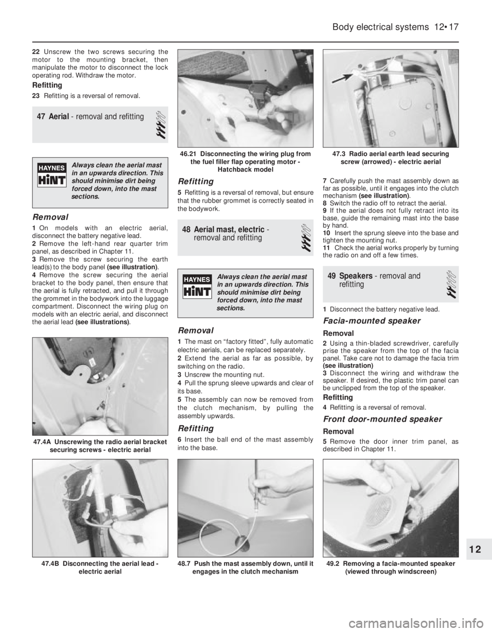
47Aerial - removal and refitting
3
Removal
1On models with an electric aerial,
disconnect the battery negative lead.
2Remove the left-hand rear quarter trim
panel, as described in Chapter 11.
3Remove the screw securing the earth
lead(s) to the body panel (see illustration).
4Remove the screw securing the aerial
bracket to the body panel, then ensure that
the aerial is fully retracted, and pull it through
the grommet in the bodywork into the luggage
compartment. Disconnect the wiring plug on
models with an electric aerial, and disconnect
the aerial lead (see illustrations).
Refitting
5Refitting is a reversal of removal, but ensure
that the rubber grommet is correctly seated in
the bodywork.
48Aerial mast, electric -
removal and refitting
3
Removal
1The mast on “factory fitted”, fully automatic
electric aerials, can be replaced separately.
2Extend the aerial as far as possible, by
switching on the radio.
3Unscrew the mounting nut.
4Pull the sprung sleeve upwards and clear of
its base.
5The assembly can now be removed from
the clutch mechanism, by pulling the
assembly upwards.
Refitting
6Insert the ball end of the mast assembly
into the base.7Carefully push the mast assembly down as
far as possible, until it engages into the clutch
mechanism (see illustration).
8Switch the radio off to retract the aerial.
9If the aerial does not fully retract into its
base, guide the remaining mast into the base
by hand.
10Insert the sprung sleeve into the base and
tighten the mounting nut.
11Check the aerial works properly by turning
the radio on and off a few times.
49Speakers - removal and
refitting
2
1Disconnect the battery negative lead.
Facia-mounted speaker
Removal
2Using a thin-bladed screwdriver, carefully
prise the speaker from the top of the facia
panel. Take care not to damage the facia trim
(see illustration)
3Disconnect the wiring and withdraw the
speaker. If desired, the plastic trim panel can
be unclipped from the top of the speaker.
Refitting
4Refitting is a reversal of removal.
Front door-mounted speaker
Removal
5Remove the door inner trim panel, as
described in Chapter 11.
Body electrical systems 12•17
47.4A Unscrewing the radio aerial bracket
securing screws - electric aerial
49.2 Removing a facia-mounted speaker
(viewed through windscreen)48.7 Push the mast assembly down, until it
engages in the clutch mechanism47.4B Disconnecting the aerial lead -
electric aerial
47.3 Radio aerial earth lead securing
screw (arrowed) - electric aerial46.21 Disconnecting the wiring plug from
the fuel filler flap operating motor -
Hatchback model
12
Always clean the aerial mast
in an upwards direction. This
should minimise dirt being
forced down, into the mast
sections.
Always clean the aerial mast
in an upwards direction. This
should minimise dirt being
forced down, into the mast
sections.
Page 32 of 525
6Remove the three securing screws, and
withdraw the speaker from the door.
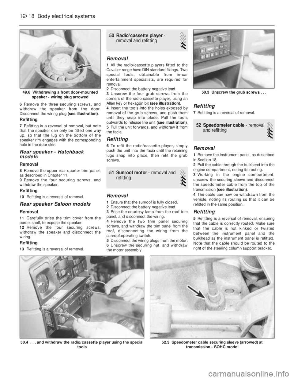
Disconnect the wiring plug (see illustration).
Refitting
7Refitting is a reversal of removal, but note
that the speaker can only be fitted one way
up, so that the lug on the bottom of the
speaker rim engages with the corresponding
hole in the door skin.
Rear speaker -Hatchback
models
Removal
8Remove the upper rear quarter trim panel,
as described in Chapter 11.
9Remove the four securing screws, and
withdraw the speaker.
Refitting
10Refitting is a reversal of removal.
Rear speaker Saloon models
Removal
11Carefully prise the trim cover from the
parcel shelf, to expose the speaker.
12Remove the four securing screws,
withdraw the speaker and disconnect the
wiring.
Refitting
13Refitting is a reversal of removal.
50Radio/cassette player -
removal and refitting
2
Removal
1All the radio/cassette players fitted to the
Cavalier range have DIN standard fixings. Two
special tools, obtainable from in-car
entertainment specialists, are required for
removal.
2Disconnect the battery negative lead.
3Unscrew the four grub screws from the
corners of the radio cassette player, using an
Allen key or hexagon bit (see illustration).
4Insert the tools into the holes exposed by
removal of the grub screws, and push them
until they snap into place. Pull the tools
outwards to release the unit (see illustration).
5Pull the unit forwards, and withdraw it from
the facia.
Refitting
6To refit the radio/cassette player, simply
push the unit into the facia until the retaining
lugs snap into place, then refit the grub
screws.
51Sunroof motor - removal and
refitting
3
Removal
1Ensure that the sunroof is fully closed.
2Disconnect the battery negative lead.
3Prise the courtesy lamp from the roof trim
panel, and disconnect the wiring.
4Remove the two trim panel securing
screws, and withdraw the trim panel from the
roof, disconnecting the wiring from the
sunroof operating switch.
5Disconnect the wiring plugs from the motor.
6Unscrew the securing nut, and withdraw
the motor assembly.
Refitting
7Refitting is a reversal of removal.
52Speedometer cable - removal
and refitting
3
Removal
1Remove the instrument panel, as described
in Section 18.
2Pull the cable through the bulkhead into the
engine compartment, noting its routing.
3Working in the engine compartment,
unscrew the securing sleeve and disconnect
the speedometer cable from the top of the
transmission (see illustration).
4The cable can now be withdrawn from the
vehicle, noting its routing so that it can be
refitted in the same position.
Refitting
5Refitting is a reversal of removal, ensuring
that the cable is correctly routed. Make sure
that the cable is not kinked or twisted
between the instrument panel and the
bulkhead as the instrument panel is refitted.
Note that the cable should be routed to the
right of the steering column support bracket.
12•18Body electrical systems
49.6 Withdrawing a front door-mounted
speaker - wiring plug arrowed
50.4 . . . and withdraw the radio/cassette player using the special
tools52.3 Speedometer cable securing sleeve (arrowed) at
transmission - SOHC model
50.3 Unscrew the grub screws . . .
Page 34 of 525
56Airbag unit, drivers side -
removal and refitting
4
Note:On power steering models in particular,
it will be advantageous to jack up the front of
the car and support it on axle stands placed
under the body side members, so that the
steering wheel can be turned more easily.
Removal
1Disconnect the battery negative lead and
cover the battery terminal. Wait a minimum of 1
minute.
2With the steering wheel positioned in the
straight-ahead position, turn it 90°clockwise
so that the left-hand spoke is accessible from
the rear.
3Using a Torx type socket, undo the first
airbag retaining bolt from the rear of the
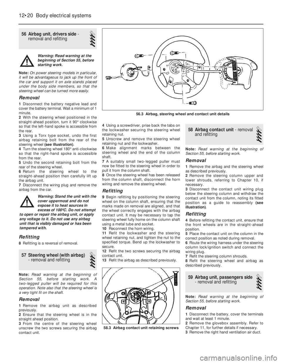
steering wheel (see illustration).
4Turn the steering wheel 180°anti-clockwise
so that the right-hand spoke is accessible
from the rear.
5Undo the second retaining bolt from the
rear of the steering wheel.
6Return the steering wheel to the
straight-ahead position then carefully lift up
the airbag unit.
7Disconnect the wiring plug and remove the
airbag from the car.
Refitting
8Refitting is a reversal of removal.
57Steering wheel (with airbag)
-removal and refitting
4
Note: Read warning at the beginning of
Section 55, before starting work. A
two-legged puller will be required for this
operation. Note also that the steering wheel is
a very tight fit on the shaft.
Removal
1Remove the airbag unit as described
previously.
2Ensure that the steering wheel is in the
straight ahead position.
3From the centre of the steering wheel
unscrew the two screws securing the airbag
contact unit.4Using a screwdriver, prise back the tabs on
the lockwasher securing the steering wheel
retaining nut.
5Unscrew and remove the steering wheel
retaining nut and the lockwasher.
6Make alignment marks between the
steering wheel and the end of the column
shaft.
7A suitably small two-legged puller must
now be fitted to the steering wheel in order to
pull it from the column shaft.
8Once the steering wheel has been released
from the column shaft, disconnect the horn
wiring and remove the steering wheel.
Refitting
9Begin refitting by positioning the steering
wheel on the column shaft, ensuring that the
marks made on removal are aligned, and that
the wheel correctly engages with the airbag
contact unit. It may be necessary to tap the
steering wheel fully home on the column shaft
using a metal tube and socket.
10Reconnect the horn wiring.
11Refit the lockwasher and the steering
wheel retaining nut, and tighten the nut to the
specified torque. Bend up the lockwasher to
secure.
12Refit the two screws securing the airbag
contact unit.
13Refit the airbag as described previously.
58Airbag contact unit -removal
and refitting
4
Note: Read warning at the beginning of
Section 55, before starting work.
Removal
1Remove the airbag and the steering wheel
as described previously.
2Remove the steering column upper and
lower shrouds, referring to Chapter 10, if
necessary.
3Disconnect the contact unit wiring plug
below the steering column and withdraw the
contact unit from the column, noting its fitted
position as a guide to reassembly (see
illustration).
Refitting
4Before refitting the contact unit, ensure that
the front wheels are in the straight-ahead
position.
5Place the contact unit on the column in the
correct position as noted during removal.
6Route the wiring harness under the steering
column lock/ignition switch and connect the
wiring plug.
7Refit the steering column shrouds.
8Refit the steering wheel and airbag as
described previously.
59Airbag unit, passengers side
- removal and refitting
4
Note: Read warning at the beginning of
Section 55, before starting work.
Removal
1Disconnect the battery, cover the terminals
and wait at least 1 minute.
2Remove the glovebox assembly. Refer to
Chapter 11, for further details if necessary.
3Remove the right hand ventilation air duct.
12•20Body electrical systems
58.3 Airbag contact unit retaining screws
56.3 Airbag, steering wheel and contact unit details
Warning: Read warning at the
beginning of Section 55, before
starting work.
Warning: Stand the unit with the
cover uppermost and do not
expose it to heat sources in
excess of 100ºC. Do not attempt
to open or repair the airbag unit, or apply
any voltage to it. Do not use any airbag
unit that is visibly damaged or has been
tampered with.
Page 53 of 525
Wiring diagrams 12•39
12
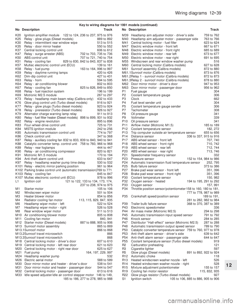
Key to wiring diagrams for 1991 models (continued)
NoDescriptionTrackNoDescriptionTrack
K20Ignition amplifier module122 to 124, 236 to 237, 975 to 976
K25Relay - glow plugs (Diesel models)889 to 892
K30Relay - intermittent rear window wipe513 to 515
K35Relay - door mirror heater550 to 552
K37Central locking control unit606 to 612
K47Relay - surge arrester (ABS)702 to 703, 735 to 736
K50ABS control unit707 to 721, 740 to 754
K51Relay - cooling fan829 to 830, 842 to 843, 837 to 838
K57Multec electronic control unit (ECU)139 to 161
K58Relay - fuel pump163 to 164, 996 to 997
K59Relay - daytime running lamps420 to 426
K62Dim-dip control unit427 to 431
K63Relay - horn594 to 595
K64Relay - air conditioning blower802 to 803
K67Relay - cooling fan825 to 826, 849 to 850
K68Relay - fuel injection system196 to 199
K69Motronic M2.5 module267 to 297
K73Relay - headlamp main beam relay (Calibra only)432 to 433
K76Glow plug control unit (Turbo diesel models)916 to 921
K77Relay - glow plugs (Turbo diesel models)923 to 924
K78Relay - preresistor (Turbo diesel models)926 to 927
K79Alternator charge warning lamp relay911 to 913
K80Relay - fuel filter heater (Diesel models)898 to 899, 931 to 932
K82Relay - engine revolution895 to 896
K83Four-wheel-drive control unit725 to 731
K84MSTS ignition module242 to 256
K85Automatic transmission control unit774 to 797
K86Check control unit347 to 368
K87Relay - auxiliary cooling fan832 to 833, 839 to 840, 940 to 941
K88Catalytic converter temp. control unit758 to 760, 966 to 968
K89Relay - rear foglamps444 to 447
K90Relay - air conditioning compressor820 to 821
K91Motronic M1.5 module170 to 194
K94Anti-theft alarm control unit633 to 647
K97Relay - headlamp washer pump time delay530 to 532
K101Relay - electric mirror parking position961 to 964
K102Parking brake control unit (automatic transmission)769 to 771
K103Relay - cooling fan845 to 847
K107Multec electronic control unit (ECU)978 to 996
L1Ignition coil121 to 122, 133 to 134, 173, 174,
237 to 238, 974 to 975
M1Starter motor105 to 106
M2Windscreen wiper motor501 to 504
M3Heater blower motor854 to 856
M4Radiator cooling fan motor113, 115, 829, 847, 935
M6Headlamp wiper motor - left522 to 524
M7Headlamp wiper motor - right526 to 528
M8Rear window wiper motor511 to 513
M10Air conditioning blower motor805 to 808
M11Cooling fan motor840, 941
M12Starter motor (Diesel models)887 to 888, 905 to 906
M13Sunroof motor assembly865 to 869
M13.1Sunroof motor866 to 868
M13.2Sunroof travel microswitch866
M13.3Sunroof travel microswitch868
M18Central locking motor - driver’s door607 to 610
M19Central locking motor - left rear door621 to 623
M20Central locking motor - right rear door625 to 627
M21Fuel pump164, 197, 229, 997
M24Headlamp washer pump532
M26Electric aerial motor588 to 589
M30Door mirror motor and heater - driver’s door538 to 541
M31Door mirror motor and heater - passenger door544 to 547
M32Central locking motor - passenger door613 to 616
M33Idle speed adjuster/idle air control stepper motor146 to 149,
185 to 186, 277 to 278, 985 to 988M39Headlamp aim adjuster motor - driver’s side759 to 762
M40Headlamp aim adjuster motor - passenger side763 to 766
M41Central locking motor - fuel filler623 to 624
M47Electric window motor - front left667 to 671
M48Electric window motor - front right685 to 689
M49Electric window motor - rear left673 to 677
M50Electric window motor - rear right691 to 695
M55Windscreen and rear window washer pump516
M60Central locking motor (Calibra models)627 to 628
M61Sunroof assembly (Calibra models)872 to 880
M61.1Sunroof motor (Calibra models)873 to 876
M61.2Relay 1 - sunroof motor (Calibra models)872 to 873
M61.3Relay 2 - sunroof motor (Calibra models)878 to 880
M62Door mirror motor - driver’s door947 to 953
M63Door mirror motor - passenger door956 to 962
P1Fuel gauge304
P2Coolant temperature gauge306
P3Clock662
P4Fuel level sender unit304
P5Coolant temperature gauge sender306
P7Tachometer308
P8Oil pressure gauge341
P9Voltmeter339
P10Oil pressure sensor341
P11Airflow meter (Motronic M1.5)185 to 189
P12Coolant temperature sensor182, 272
P13Trip computer outside air temperature sensor655 to 656
P14Distance sensor336 to 337, 915 to 916
P17ABS wheel sensor - front left707, 740
P18ABS wheel sensor - front right710, 742
P19ABS wheel sensor - rear left712, 744
P20ABS wheel sensor - rear right713, 746
P21Speedometer frequency sensor332
P23Pressure sensor152 to 154, 984 to 986
P24Automatic transmission fluid temperature sensor252, 795
P25Bulb failure sensor373 to 386
P27Brake pad wear sensor - front left351, 396
P28Brake pad wear sensor - front right351, 396
P30Coolant temperature sensor150, 982
P32Oxygen sensor - heated194 to 195, 291 to 292
P33Oxygen sensor157, 991
P34Throttle position sensor/potentiometer158 to 160, 180 to 181,
777 to 778, 987 to 989
P35Crankshaft speed/position sensor189 to 191,
281 to 282, 982 to 984
P39Trailer bulb failure sensor368 to 370, 387 to 389
P43Electronic speedometer336
P44Air mass meter (Motronic M2.5)294 to 298
P45Automatic transmission input speed sensor791 to 792
P46Knock sensor284 to 285
P47Distributor “Hall-effect” sensor (Motronic M2.5)287 to 288
P48Automatic transmission output speed sensor789 to 790
P50Catalytic converter temperature sensor759 to 760, 977 to 978
P53Anti-theft alarm sensor - driver’s side639 to 642
P54Anti-theft alarm sensor - passenger side644 to 647
P55Coolant temperature sensor (Turbo diesel models)919
R2Carburettor preheating121
R3Cigarette lighter597
R5Glow plugs (Diesel models)891 to 892, 922 to 924
R12Automatic choke118
R13Heated windscreen washer nozzle - left526
R14Heated windscreen washer nozzle - right528
R15Mixture adjustment potentiometer155 to 157
R19Cooling fan motor resistor115, 832, 935
R22Glow plugs resistor (Turbo diesel models)927
S1Ignition switch105 to 106, 885 to 886, 905 to 906
Page 90 of 525
HEI (High Energy Ignition)
system
5This comprises of a breakerless distributor
and an electronic switching/amplifier module
along with the coil and spark plugs.
6The electrical impulse that is required to
switch off the low tension circuit is generated
by a magnetic trigger coil in the distributor. A
trigger wheel rotates within a magnetic stator,
the magnetic field being provided by a
permanent magnet. The magnetic field across
the two poles (stator arm and trigger wheel) is
dependent on the air gap between the two
poles. When the air gap is at its minimum, the
trigger wheel arm is directly opposite the
stator arm, and this is the trigger point. As the
magnetic flux between the stator arm and
trigger wheel varies, a voltage is induced in the
trigger coil mounted below the trigger wheel.
This voltage is sensed and then amplified by
the electronic module, and used to switch off
the low tension circuit. There is one trigger arm
and one stator arm for each cylinder.
7The ignition advance is a function of the
distributor, and is controlled both
mechanically and by a vacuum-operated
system. The mechanical governor mechanism
consists of two weights that move out from
the distributor shaft due to centrifugal force as
the engine speed rises. As the weights move
outwards, they rotate the trigger wheel
relative to the distributor shaft and so
advance the spark. The weights are held in
position by two light springs, and it is the
tension of the springs that is largely
responsible for correct spark advancement.
8The vacuum control consists of a
diaphragm, one side of which is connected by
way of a small-bore hose to the carburettor,
and the other side to the distributor.
Depression in the inlet manifold and
carburettor, which varies with engine speed
and throttle position, causes the diaphragm to
move, so moving the baseplate and
advancing or retarding the spark. A fine
degree of control is achieved by a spring in
the diaphragm assembly.
MSTS-i (Microprocessor-
controlled Spark Timing System)
9This system comprises a “Hall-effect”
distributor (or a crankshaft speed/position
sensor on X 16 SZ models), a manifold pressure
sensor, an oil temperature sensor, and a
module, along with the coil and spark plugs.
10On 1.6 litre models, the electrical impulse
that is required to switch off the low tension
circuit is generated by a sensor in the
distributor. A trigger vane rotates in the gap
between a permanent magnet and the sensor.
The trigger vane has four cut-outs, one for
each cylinder. When one of the trigger vane
cut-outs is in line with the sensor, magnetic
flux can pass between the magnet and the
sensor. When a trigger vane segment is in line
with the sensor, the magnetic flux is diverted
through the trigger vane away from thesensor. The sensor senses the change in
magnetic flux, and sends an impulse to the
MSTS-i module, which switches off the low
tension circuit.
11On 1.8 litre models, the electrical impulse
that is required to switch off the low tension
circuit is generated by a crankshaft
speed/position sensor, which is activated by a
toothed wheel on the crankshaft. The toothed
wheel has 35 equally spaced teeth, with a gap
in the 36th position. The gap is used by the
sensor to determine the crankshaft position
relative to TDC (top dead centre) of No 1 piston.
12Engine load information is supplied to the
MSTS-i module by a pressure sensor, which
is connected to the carburettor by a vacuum
pipe. Additional information is supplied by an
oil temperature sensor. The module selects
the optimum ignition advance setting based
on the information received from the sensors.
The degree of advance can thus be constantly
varied to suit the prevailing engine conditions.
Multec, with MSTS-i
13The ignition system is fully electronic in
operation and incorporates the Electronic
Control Unit (ECU) mounted in the driver’s
footwell. A distributor (driven off the camshaft
left-hand end and incorporating the amplifier
module) as well as the octane coding plug,
the spark plugs, HT leads, ignition HT coil and
associated wiring.
14The ECU controls both the ignition system
and the fuel injection system, integrating the
two in a complete engine management
system. Refer to Chapters 4B and 4C for
further information that is not detailed here.
15For ignition the ECU receives information
in the form of electrical impulses or signals
from the distributor (giving it the engine speed
and crankshaft position), from the coolant
temperature sensor (giving it the engine
temperature) and from the manifold absolute
pressure sensor (giving it the load on the
engine). In addition, the ECU receives input
from the octane coding plug (to provide
ignition timing appropriate to the grade of fuel
used) and from, where fitted, the automatic
transmission control unit (to smooth gear
changing by retarding the ignition as changes
are made).
16All these signals are compared by the
ECU with set values pre-programmed
(mapped) into its memory. Considering this
information, the ECU selects the ignition
timing appropriate to those values and
controls the ignition HT coil by way of the
amplifier module accordingly.
17The system is so sensitive that, at idle
speed, the ignition timing may be constantly
changing; this should be remembered if trying
to check the ignition timing.
18The system fitted to C18 NZ models, is
similar to that described above, except that
the amplifier module is separate. The ECU
determines engine speed and crankshaft
position using a sensor mounted in the
right-hand front end of the engine’s cylinderblock; this registers with a 58-toothed disc
mounted on the crankshaft so that the gap left
by the missing two teeth provides a reference
point, so enabling the ECU to recognise TDC.
19Note that this simplifies the distributor’s
function, which is merely to distribute the HT
pulse to the appropriate spark plug; it has no
effect whatsoever on the ignition timing.
DIS (Direct Ignition System)
20On all X16 SZ engines, and on C20 XE
(DOHC) engines from 1993-on, a DIS (Direct
Ignition System) module is used in place of
the distributor and coil. On the X16 SZ engine
the DIS module is attached to the camshaft
housing in the position normally occupied by
the distributor. On the C20 XE engine, a
camshaft phase sensor is attached to the
cylinder head at the non-driven end of the
exhaust camshaft, in the position normally
occupied by the distributor. The DIS module
is attached, by a bracket, to the cylinder head
at the non-driven end of the inlet camshaft.
21The DIS module consists of two ignition
coils and an electronic control module housed
in a cast casing. Each ignition coil supplies
two spark plugs with HT voltage. One spark is
provided in a cylinder with its piston on the
compression stroke, and one spark is
provided to a cylinder with its piston on the
exhaust stroke. This means that a “wasted
spark” is supplied to one cylinder during each
ignition cycle, but this has no detrimental
effect. This system has the advantage that
there are no moving parts (therefore there is
no wear), and the system is largely
maintenance-free.
Motronic M4.1 and M1.5
22This system controls both the ignition and
the fuel injection systems.
23The Motronic module receives information
from a crankshaft speed/position sensor, an
engine coolant temperature sensor mounted
in the thermostat housing. A throttle position
sensor, an airflow meter, and on models fitted
with a catalytic converter, an oxygen sensor
mounted in the exhaust system (Chapter 4C).
24The module provides outputs to control
the fuel pump, fuel injectors, idle speed and
ignition circuit. Using the inputs from the
various sensors, the module computes the
optimum ignition advance, and fuel injector
pulse duration, to suit the prevailing engine
conditions. This system gives very accurate
control of the engine under all conditions,
improving fuel consumption and driveability,
and reducing exhaust gas emissions.
25Further details of the fuel injection system
components are given in Chapter 4B.
Motronic M2.5 and M2.8
26The system is similar to that described for
SOHC models, with the following differences.
27Along with the crankshaft speed/position
sensor, a “Hall-effect” distributor is used
(similar to that described in this Section, with
the MSTS-i system).
Engine electrical systems 5•3
5
Page 91 of 525
28The system also incorporates a separate
ignition amplifier module that transmits
amplified signals from the main system
module to trigger the HT pulse from the
ignition coil. The module is mounted on the
ignition coil’s bracket/baseplate.
29Additionally, the Motronic module
receives information from a cylinder
block-mounted knock sensor, which senses
“knocking” (or pre-ignition) just as it begins to
occur, enabling the module to retard the
ignition timing, thus preventing engine
damage.
Simtec 56.1
30This system uses increased amount of
electronic components instead of mechanical
parts as sensors and actuators with the
Simtec engine management system. This
provides more precise operating data as well
as greater problem free motoring.
31The control unit is equipped with
electronic ignition control. Called ‘Micropro-
cessor Spark Timing System, inductive
triggered’, (or MSTS-i), and means that the
mechanical high voltage distributor is no
longer needed. It is located behind the trim
panel, on the right-hand side footwell (door
pillar).
32The ignition coil is replaced by a dual
spark ignition coil, which is switched directly
by the output stages in the control unit.
33A camshaft sensor will maintain
emergency operation, should the crankshaft
inductive pulse pick-up, malfunction. These
sense TDC (‘Top Dead Centre’), crankshaft
angle and engine speed. The signals are used
by the control unit to calculate ignition point
and for fuel injection.
34The ‘hot film airflow meter’ determines the
mass of air taken in by the engine. The system
uses this information to calculate the correct
amount of fuel needed for injection in the
engine.
35The air inlet temperature sensor (NTC), is
fitted in the air inlet duct between the air
cleaner and the hot mass air flow meter.
36A controlled canister purge valve is
actuated by the system. The tank ventilation is
monitored closely with the Lambda control (or
oxygen sensor) and adaptation by the
computer within the control unit.
37A knock control system is also fitted. This
eliminates the need for octane number
adjustment, as it is performed automatically
through the control unit.
3Electrical system -
precautions
1It is necessary to take extra care when
working on the electrical system, to avoid
damage to semi-conductor devices (diodes
and transistors), and to avoid the risk of
personal injury. Along with the precautions
given in the “Safety first!” Section at the
beginning of this manual, take note of the
following points when working on the system.
2Always remove rings, watches, etc. before
working on the electrical system. Even with
the battery disconnected, discharge could
occur if a component live terminal is earthed
through a metal object. This could cause a
shock or nasty burn.
3Do not reverse the battery connections.
Components such as the alternator, or any
other component having semi-conductor
circuitry, could be irreparably damaged.
4If the engine is being started using jump
leads and a slave battery, connect the
batteries positive to positive and negative to
negative. This also applies when connecting a
battery charger.
5Never disconnect the battery terminals, or
alternator multi-plug connector, when the
engine is running.
6The battery leads and alternator wiring
must be disconnected before carrying out any
electric welding on the vehicle.
7Never use an ohmmeter of the type
incorporating a hand-cranked generator for
circuit or continuity testing.
8Engine management modules are very
sensitive components, and certain
precautions must be taken, to avoid damage
to the module when working on a vehicle
equipped with an engine management
system, as follows.
9When carrying out welding operations on
the vehicle using electric welding equipment,
the battery and alternator should be
disconnected.
10Although underbonnet-mounted modules
will tolerate normal underbonnet conditions,
they can be adversely affected by excess heat
or moisture. If using welding equipment or
pressure washing equipment near the
module, take care not to direct heat, or jets of
water or steam, at the module. If this cannot
be avoided, remove the module from the
vehicle, and protect its wiring plug with a
plastic bag.
11Before disconnecting any wiring, or
removing components, always ensure that the
ignition is switched off.
12Do not attempt to improvise fault
diagnosis procedures using a test lamp or
multimeter, as irreparable damage could be
caused to the module.13After working on ignition/engine
management system components, ensure
that all wiring is correctly reconnected before
reconnecting the battery or switching on the
ignition.
14Any ignition system that uses a
“Hall-effect” generator in the distributor,
cannot be tested. Test equipment that uses
its own power source (e.g. an ohmmeter),
when connected to the distributor or the
“Hall-effect” generator, will be damaged.
4Ignition system testing -
general
3
Note: Refer to Section 3 before proceeding.
Always switch off the ignition before
disconnecting or connecting any component
and when using a multi-meter to check
resistances. Any voltmeter or multi-meter
used to test ignition system components must
have an impedance of 10 meg ohms or
greater
1Electronic ignition system components are
normally very reliable. Most faults are far more
likely to be due to loose or dirty connections,
or to “tracking” of HT voltage due to dirt,
dampness or damaged insulation than to
component failure. Always check all wiring
thoroughly before condemning an electrical
component and work methodically to
eliminate all other possibilities before deciding
that a particular component is faulty.
2The old practice of checking for a spark by
holding the live end of a HT lead a short
distance away from the engine is not
recommended. Not only is there a high risk of
a powerful electric shock, but the ignition coil
or amplifier module will be damaged.
Similarly, never try to “diagnose” misfires by
pulling off one HT lead at a time. Note also
that the ECU is at risk if the system is
triggered with an open (i.e., not properly
earthed) HT circuit; ECU’s are very expensive
to replace, so take care!
3If you are in any doubt as to your skill and
ability to test an ignition system component or
if you do not have the required equipment,
take the vehicle to a suitably equipped
Vauxhall dealer. It is better to pay the labour
charges involved in having the vehicle
checked by an expert than to risk damage to
the system or to yourself.
4If the engine either will not turn over at all,
or only turns very slowly, check the battery
and starter motor. Connect a voltmeter across
the battery terminals (meter positive probe to
battery positive terminal) and disconnect the
ignition coil HT lead from the distributor cap
and earth. Note the voltage reading obtained
while turning over the engine on the starter for
(no more than) ten seconds. If the reading
obtained is less than approximately 9.5 volts,
check the battery, battery connections, starter
motor and charging system.
5•4Engine electrical systems
Warning: The HT voltage
generated by an electronic
ignition system is extremely
high and, in certain
circumstances, could prove fatal. Take
care to avoid receiving electric shocks
from the HT side of the ignition system.
Do not handle HT leads, or touch the
distributor or coil, when the engine is
running. If tracing faults in the HT circuit,
use well-insulated tools to manipulate live
leads