ECU OPEL CALIBRA 1988 Service Workshop Manual
[x] Cancel search | Manufacturer: OPEL, Model Year: 1988, Model line: CALIBRA, Model: OPEL CALIBRA 1988Pages: 525, PDF Size: 58.26 MB
Page 115 of 525

6Carefully withdraw the bumper from the
vehicle.
Refitting
7Refitting is a reversal of removal.
Rear bumper
Removal
8Remove the rear trim panel from the
luggage compartment by prising up the top
edge to release the clips, then lift the panel
upwards to free it from the lower locating
tags. The bumper retaining nuts are now
exposed (see illustrations).
9Note that the bumper is removed as a
complete assembly with its lower trim panel.
10Disconnect the battery negative lead, then
prise the number plate lamp from the bumper,
and disconnect the wiring.
11Unscrew the bumper retaining nuts, and
recover the washers. On DOHC models, the
bumper securing nuts are accessible from
underneath the vehicle.
12Where fitted, remove the special locking
rivets, one each side, securing the bumper to
the wheel arch.
13Additional clips may be present on the
underside of the bumper which must also be
removed.
14Release the bumper retaining clips at the
front edges of the bumper by tapping the
centre pin through the expanding clip, using a
pin punch or similar. The pin will drop out as it
is pushed through - recover it for refitting.
15Push each end of the bumper towards the
rear of the vehicle, then pull the end of the
bumper from the rear wing.16Carefully withdraw the bumper from the
vehicle, taking care not to strain the number
plate lamp wiring.
Refitting
17Refitting is a reversal of removal. The
expanding clips at the front edges of the
bumper are secured by pushing the pin into
the clip until flush.
29Radiator grille panel -
removal and refitting
2
All SOHC models
Removal
1With the bonnet fully open and supported,
pull the upper edge of the grille panel
forwards and free the retaining clips using a
screwdriver. Then lift the panel to release the
lower locating lugs from their grommets in the
lower body front panel (see illustration).
Refitting
2Refitting is a reversal of removal, but ensure
that the lower locating lugs seat correctly in
their grommets, and take care not to push the
grommets from their holes in the body front
panel.
DOHC and 1993-on models
Removal
3Extract the three screws securing the grille
panel to the body front panel, then lift the
grille panel to release the lower locating lugs
from their grommets in the lower body front
panel.
Refitting
4Refitting is a reversal of removal, with
reference to paragraph 2.
30Windscreen cowl panel -
removal and refitting
2
Removal
1Remove the wiper arms, referring to
Chapter 12, if necessary.2Disconnect the washer fluid hose from the
reservoir, and feed it through the cowl panel,
noting its routing as a guide to refitting. Be
prepared for fluid spillage.
3Where applicable, disconnect the battery
negative lead, then disconnect the
underbonnet lamp wiring plug and feed it
through the cowl panel, noting its routing as a
guide to refitting.
4Working from one end of the cowl panel,
carefully prise the panel from the body. Care
must be taken, as the panel is easily
damaged.
Refitting
5Refitting is a reversal of removal, ensuring
that the panel is correctly seated along its
length, and that the washer fluid hose, and
where applicable the underbonnet lamp
wiring, is correctly routed.
31Wheel arch liners - general
2
1The plastic wheel arch liners are secured by
a combination of self-tapping screws and
plastic clips. Removal and refitting is self
explanatory, remembering the following
points (see illustration).
2Some of the securing clips may be held in
place using a central pin, which must be
tapped out to release the clip.
3The clips are easily broken during removal,
and it is advisable to obtain a few spare clips
for possible use when refitting.
11•12Bodywork and fittings
28.8B . . . to expose the bumper securing
nuts
31.1 Removing a wheel arch liner29.1 Freeing a radiator grille panel
retaining clip using a screwdriver
28.8A Remove the trim panel . . .28.5 Front bumper retaining clips released
from body
Page 116 of 525

4Certain models may have additional
underbody shields and splashguards fitted,
which may be attached to the wheel arch liners.
32Engine undershield (DOHC
models) - removal and
refitting
2
Removal
1Apply the handbrake, then jack up the front
of the vehicle, and support on axle stands
(see “Jacking and Vehicle Support”).
2Extract the two securing screws, and
remove the oil filter access panel.
3Working around the edges of the splash
shield, remove the self tapping screws that
secure the shield to the body, noting that
some of the screws also secure the wheel
arch liners.
4With the help of an assistant, pull the shield
from the vehicle, and place it to one side to
avoid damage.
Refitting
5Refitting is a reversal of removal.
33Fuel filler flap -removal and
refitting
2
Removal
1Open the flap for access to the four screws
securing the flap to the rear wing.2Remove the securing screws, and withdraw
the flap.
Refitting
3Refitting is a reversal of removal.
34Sunroof components -
removal and refitting
4
Note:The sunroof is a complex piece of
equipment consisting of a large number of
components. It is strongly recommended that
the sunroof mechanism is not disturbed unless
necessary. If the sunroof mechanism is faulty, or
requires overhaul, consult a dealer for advice.
Glass panel
Removal
1Push the sunshade fully rearwards, and
open the glass panel halfway.
2Extract the four securing screws from the
front edge of the guide rail plastic surround,
and withdraw the surround down through the
sunroof aperture (see illustrations).
3Move the glass panel forward, and open it
to its tilt position.
4Prise the plastic trim strips from the guide
rails, to expose the glass panel securing
screws (see illustration).5Extract the three securing screws from
each guide rail, and where applicable, recover
the lockwashers (see illustration).
6Carefully lift the glass panel from the roof
aperture, taking care not to damage the
vehicle paintwork (see illustration).
Refitting
7Refitting is a reversal of removal,
remembering the following points.
8Before refitting the glass panel, measure
the distance between the mounting flanges.
Bend the flanges if necessary to achieve the
desired dimension (see illustration).
Bodywork and fittings 11•13
34.4 Prising a plastic trim strip from the
guide rail
34.6 Lifting the glass panel from the roof
aperture
34.5 Loosening a glass panel securing
screw
34.2B . . . and withdraw the guide rail
plastic surround34.2A Extract the four securing screws . . .
11
34.8 Sunroof glass panel mounting
flange dimension
1 Mounting flange
2 Nut
3 Protective foil
A-A Cross-section cutting point
(Dimensions in mm)
Page 117 of 525
9Where applicable, ensure that the glass
panel securing screw lockwashers engage
with the locating pins on the guide rails.
10Before fully tightening the glass panel
securing screws, close the panel, and adjust
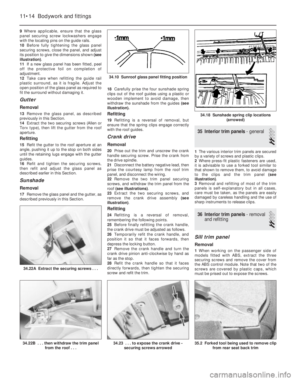
its position to give the dimensions shown (see
illustration).
11If a new glass panel has been fitted, peel
off the protective foil on completion of
adjustment.
12Take care when refitting the guide rail
plastic surround, as it is fragile. Adjust the
open position of the glass panel as required to
fit the surround without damaging it.
Gutter
Removal
13Remove the glass panel, as described
previously in this Section.
14Extract the two securing screws (Allen or
Torx type), then lift the gutter from the roof
aperture.
Refitting
15Refit the gutter to the roof aperture at an
angle, pushing it up to the stop on both sides
until the retaining lugs engage with the gutter
guides.
16Refit and tighten the securing screws,
then refit and adjust the glass panel as
described earlier in this Section.
Sunshade
Removal
17Remove the glass panel and the gutter, as
described previously in this Section. 18Carefully prise the four sunshade spring
clips out of the roof guides using a plastic or
wooden implement to avoid damage, then
withdraw the sunshade from the guides (see
illustration).
Refitting
19Refitting is a reversal of removal, but
ensure that the spring clips engage correctly
with the roof guides.
Crank drive
Removal
20Prise out the trim and unscrew the crank
handle securing screw. Prise the crank from
the drive spindle.
21Disconnect the battery negative lead, then
prise the courtesy lamp from the roof trim
panel, and disconnect the wiring.
22Remove the two trim panel securing
screws, and withdraw the trim panel from the
roof (see illustrations).
23Extract the two securing screws, and
remove the crank drive assembly (see
illustration).
Refitting
24Refitting is a reversal of removal,
remembering the following points.
25Before finally refitting the crank handle,
the crank drive must be adjusted as follows.
26Temporarily refit the crank handle, and
position it so that it faces forwards, then
depress the locking button.
27Remove the crank handle and turn the
crank drive pinion anti-clockwise by hand as
far as the stop.
28Refit the crank handle so that it faces
directly forwards, then tighten the securing
screw and refit the trim.
35Interior trim panels -general
2
1The various interior trim panels are secured
by a variety of screws and plastic clips.
2Where press-fit plastic fasteners are used,
it is advisable to use a forked tool similar to
that shown to remove them, to avoid damage
to the clips and the trim panel (see
illustration).
3Removal and refitting of most of the trim
panels is self-explanatory but in all cases,
care must be taken, as the panels are easily
damaged by careless handling and the use of
sharp instruments to release clips.
36Interior trim panels -removal
and refitting
2
Sill trim panel
Removal
1When working on the passenger side of
models fitted with ABS, extract the three
securing screws and remove the cover from
the ABS control module. Note that two of the
screws are covered by plastic caps, which
must be prised out to expose the screws.
11•14Bodywork and fittings
34.22A Extract the securing screws . . .
35.2 Forked tool being used to remove clip
from rear seat back trim34.23 . . . to expose the crank drive -
securing screws arrowed34.22B . . . then withdraw the trim panel
from the roof . . .
34.18 Sunshade spring clip locations
(arrowed)
34.10 Sunroof glass panel fitting position
Page 118 of 525

2The sill trim panel can be removed by
simply prising it upwards to release the
securing clips from the floor (see illustration).
Refitting
3Refitting is a reversal of removal, but ensure
that the panel is correctly seated with its top
edge located under the sill weatherstrip.
Footwell side trim panel
Removal
4Release the front end of the sill trim panel
from the floor, as described previously.
5Prise the footwell side trim panel from the
footwell (see illustration). If necessary, pull
the weatherstrip from the edge of the door
aperture.
Refitting
6Refitting is a reversal of removal, but ensure
that the trim panels are correctly seated under
the weatherstrip.
Front body pillar trim panel
Removal
7Prise the trim panel from the body pillar to
release the six retaining clips. If necessary, pull
the weatherstrip from the edge of the pillar.
Refitting
8Refitting is a reversal of removal, but ensure
that the trim panel is correctly seated under
the weatherstrip.
Centre body pillar trim panels
Removal
9Remove the sill trim panel, as described
previously in this Section.
10Prise the weatherstrips from the sides of
the body pillar (see illustration).
11Pull the lower trim panel from the pillar to
release the retaining clips (see illustration).
12With the lower trim panel removed, the
upper trim panel can be withdrawn in the
same way after unbolting the upper seat belt
mounting. Prise off the trim to expose the
upper seat belt mounting bolt, then unscrew
the bolt and recover the spacer.
Refitting
13Refitting is a reversal of removal, but
ensure that the trim panels are seated
correctly under the weatherstrips.
Rear quarter trim panels
14Prise off the trim and unbolt the seat belt
upper mounting from the body pillar. Recover
the spacer.
15Pull back the weatherstrip from the rear
edge of the rear door aperture. On Hatchback
models, remove the parcel shelf.16Remove the screws securing the upper rear
quarter trim panel to the body. Note that all the
screws are of the Torx type. When working on
the right-hand side of Hatchback models, it will
be necessary to open the first-aid kit/warning
triangle cover flap in the luggage compartment
for access to some of the screws.
17Withdraw the upper seat quarter trim
panel carefully, taking care not to damage
surrounding panels (see illustration). Where
applicable, disconnect the wiring from the
loudspeaker.
18With the upper rear quarter trim panel
removed, the lower trim panel can be
removed.
19The lower rear quarter trim panel is
secured by a variety of screws, nuts and clips,
depending upon model. Removal and refitting
of the panel is self-explanatory, remembering
the points made in Section 35. Note that the
rubber stop must be removed from the seat
catch before the trim panel can be withdrawn
(see illustrations).
Luggage compartment rear trim
panel
20Prise the trim panel from the rear of the
luggage compartment to release the securing
clips.
21Refitting is a reversal of removal.
Tailgate trim panels (Hatchback
models)
22The tailgate trim panels are secured by
screws, and removal and refitting are
self-explanatory. Note that the lower side
panel securing screws also secure the rear
panel.
Bodywork and fittings 11•15
36.10 Pull the weatherstrip from the sides
of the body pillar . . .
36.19B Withdrawing the lower rear quarter
trim panel - Hatchback model36.19A Removing the rubber stop from the
seat catch36.17 Withdrawing the upper rear quarter
trim panel - Hatchback model
36.11 . . . then pull the lower trim panel
from the pillar
36.5 Removing the driver’s footwell side
trim panel36.2 Sill trim panel removed to expose
securing clips
11
Page 119 of 525

37Facia panels - removal and
refitting
3
Footwell trim panels
Removal
1The lower footwell trim panels on the
driver’s and passenger sides are secured by
turnbuckle type plastic clips.2To remove a panel, use a screwdriver to
turn the heads of the clips through 90°(see
illustration), then withdraw the panel from the
facia.
Refitting
3Refitting is a reversal of removal.
Driver’s side lower facia panel
Removal
4Open the flap covering the fusebox to
expose the four lower facia panel securing
screws.
5Remove the four screws, then lower the
panel and pull it towards the driver’s door to
release the two securing clips. Withdraw the
panel from the facia (see illustrations).
Refitting
6Refitting is a reversal of removal.
Steering column shrouds
Removal
7On models with an adjustable tilt steering
column, move the column to its fully raised
position, then unscrew the adjuster lever (see
illustration).
8Turn the steering wheel as necessary to
expose one of the front steering column
shroud securing screw covers.
9Prise out the cover, and remove the column
shroud securing screw, then turn the steering
wheel to enable the remaining cover and
screw to be removed (see illustrations).
10Remove the three securing screws from
the underside of the lower column shroud,
then remove the lower and upper shrouds
(see illustrations).
11•16Bodywork and fittings
37.2 Releasing a footwell trim panel
securing clip37.5B . . . then withdraw the lower facia
panel
37.10C . . . and upper shrouds (steering
wheel removed)37.10B . . . then remove the lower . . .37.10A Remove the three lower column
shroud securing screws . . .
37.9B . . . then remove the front column
shroud securing screws37.9A Prise out the covers . . .37.7 Removing the column adjuster lever
37.5A Remove the four securing screws
from the fusebox aperture . . .
Before removing any of the
facia panels, the battery
negative lead should be
disconnected, as several
permanently live feed wires are routed
behind the facia.
Page 120 of 525
Refitting
11Refitting is a reversal of removal, but
make sure that the column switch gaiters
engage in the cut-outs in the upper shroud.
Instrument panel lower trim
panel
Removal
12Remove the steering column shrouds, as
described previously in this Section.
13The panel is secured by clips at either
end, which must be released by pulling the
ends of the panel from the facia (see
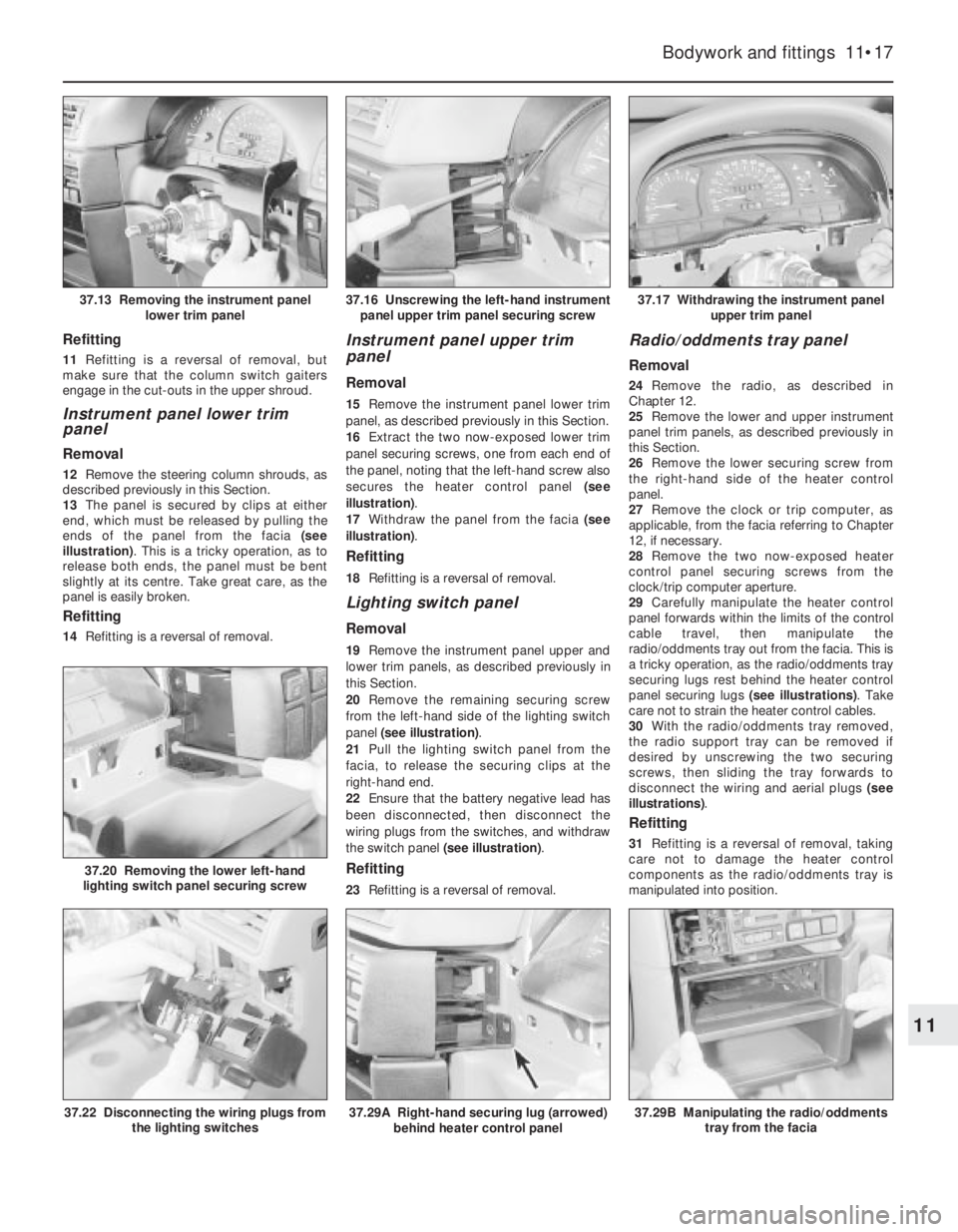
illustration). This is a tricky operation, as to
release both ends, the panel must be bent
slightly at its centre. Take great care, as the
panel is easily broken.
Refitting
14Refitting is a reversal of removal.
Instrument panel upper trim
panel
Removal
15Remove the instrument panel lower trim
panel, as described previously in this Section.
16Extract the two now-exposed lower trim
panel securing screws, one from each end of
the panel, noting that the left-hand screw also
secures the heater control panel (see
illustration).
17Withdraw the panel from the facia (see
illustration).
Refitting
18Refitting is a reversal of removal.
Lighting switch panel
Removal
19Remove the instrument panel upper and
lower trim panels, as described previously in
this Section.
20Remove the remaining securing screw
from the left-hand side of the lighting switch
panel (see illustration).
21Pull the lighting switch panel from the
facia, to release the securing clips at the
right-hand end.
22Ensure that the battery negative lead has
been disconnected, then disconnect the
wiring plugs from the switches, and withdraw
the switch panel (see illustration).
Refitting
23Refitting is a reversal of removal.
Radio/oddments tray panel
Removal
24Remove the radio, as described in
Chapter 12.
25Remove the lower and upper instrument
panel trim panels, as described previously in
this Section.
26Remove the lower securing screw from
the right-hand side of the heater control
panel.
27Remove the clock or trip computer, as
applicable, from the facia referring to Chapter
12, if necessary.
28Remove the two now-exposed heater
control panel securing screws from the
clock/trip computer aperture.
29Carefully manipulate the heater control
panel forwards within the limits of the control
cable travel, then manipulate the
radio/oddments tray out from the facia. This is
a tricky operation, as the radio/oddments tray
securing lugs rest behind the heater control
panel securing lugs (see illustrations). Take
care not to strain the heater control cables.
30With the radio/oddments tray removed,
the radio support tray can be removed if
desired by unscrewing the two securing
screws, then sliding the tray forwards to
disconnect the wiring and aerial plugs (see
illustrations).
Refitting
31Refitting is a reversal of removal, taking
care not to damage the heater control
components as the radio/oddments tray is
manipulated into position.
Bodywork and fittings 11•17
37.17 Withdrawing the instrument panel
upper trim panel
37.29B Manipulating the radio/oddments
tray from the facia37.29A Right-hand securing lug (arrowed)
behind heater control panel37.22 Disconnecting the wiring plugs from
the lighting switches
37.20 Removing the lower left-hand
lighting switch panel securing screw
37.16 Unscrewing the left-hand instrument
panel upper trim panel securing screw37.13 Removing the instrument panel
lower trim panel
11
Page 121 of 525
Glovebox assembly
Removal
32Carefully prise the side trim panels from
the passenger’s oddments tray, using a
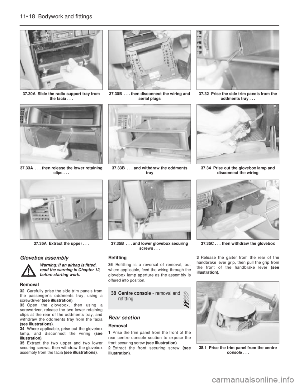
screwdriver (see illustration).
33Open the glovebox, then using a
screwdriver, release the two lower retaining
clips at the rear of the oddments tray, and
withdraw the oddments tray from the facia
(see illustrations).
34Where applicable, prise out the glovebox
lamp, and disconnect the wiring (see
illustration).
35Extract the two upper and two lower
securing screws, then withdraw the glovebox
assembly from the facia (see illustrations).
Refitting
36Refitting is a reversal of removal, but
where applicable, feed the wiring through the
glovebox lamp aperture as the assembly is
offered into position.
38Centre console - removal and
refitting
2
Rear section
Removal
1Prise the trim panel from the front of the
rear centre console section to expose the
front securing screw (see illustration).
2Extract the front securing screw (see
illustration).3Release the gaiter from the rear of the
handbrake lever grip, then pull the grip from
the front of the handbrake lever (see
illustration).
11•18Bodywork and fittings
37.30A Slide the radio support tray from
the facia . . .37.32 Prise the side trim panels from the
oddments tray . . .
37.35C . . . then withdraw the glovebox37.35B . . . and lower glovebox securing
screws . . .37.35A Extract the upper . . .
37.34 Prise out the glovebox lamp and
disconnect the wiring37.33B . . . and withdraw the oddments
tray37.33A . . . then release the lower retaining
clips . . .
37.30B . . . then disconnect the wiring and
aerial plugs
38.1 Prise the trim panel from the centre
console . . .
Warning: If an airbag is fitted,
read the warning in Chapter 12,
before starting work.
Page 122 of 525
4Pull the cassette storage box or the rubber
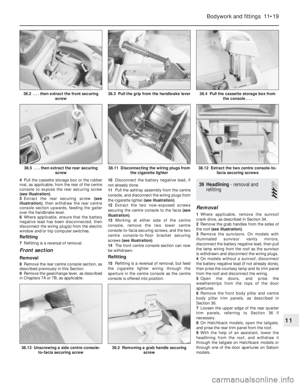
mat, as applicable, from the rear of the centre
console to expose the rear securing screw
(see illustration).
5Extract the rear securing screw (see
illustration), then withdraw the rear centre
console section upwards, feeding the gaiter
over the handbrake lever.
6Where applicable, ensure that the battery
negative lead has been disconnected, then
disconnect the wiring plug(s) from the electric
window and/or trip computer switches.
Refitting
7Refitting is a reversal of removal.
Front section
Removal
8Remove the rear centre console section, as
described previously in this Section.
9Remove the gearchange lever, as described
in Chapters 7A or 7B, as applicable. 10Disconnect the battery negative lead, if
not already done.
11Pull the ashtray assembly from the centre
console, and disconnect the wiring plugs from
the cigarette lighter (see illustration).
12Extract the two now-exposed screws
securing the centre console to the facia (see
illustration).
13Working at either side of the centre
console, remove the two lower centre
console-to-facia securing screws, and the two
centre console-to-floor bracket securing
screws (see illustration).
14The front centre console section can now
be withdrawn.
Refitting
15Refitting is a reversal of removal, but feed
the cigarette lighter wiring through the
aperture in the centre console as the centre
console is offered into position.
39Headlining -removal and
refitting
3
Removal
1Where applicable, remove the sunroof
crank drive, as described in Section 34.
2Remove the grab handles from the sides of
the roof (see illustration).
3Remove the sunvisors. On models with
illuminated sunvisor vanity mirrors,
disconnect the battery negative lead, then pull
the lamp wiring from the roof as the sunvisor
is withdrawn and disconnect the wiring plugs.
4On models without a sunroof, disconnect
the battery negative lead (if not already done),
then prise the courtesy lamp and its trim panel
from the roof and disconnect the wiring.
5Open the doors, and prise the
weatherstrips from the tops of the door
apertures.
6Remove the front body pillar and centre
body pillar trim panels, as described in
Section 36.
7Loosen the upper edge of the rear quarter
trim panels, referring to Section 36 if
necessary.
8On Hatchback models, open the tailgate,
and prise the rear trim panel from the roof.
9With the help of an assistant, lower the
headlining from the roof, and withdraw it
through the tailgate on Hatchback models or
through one of the door apertures on Saloon
models.
Bodywork and fittings 11•19
38.4 Pull the cassette storage box from
the console . . .
38.12 Extract the two centre console-to-
facia securing screws38.11 Disconnecting the wiring plugs from
the cigarette lighter
38.3 Pull the grip from the handbrake lever38.2 . . . then extract the front securing
screw
11
38.5 . . . then extract the rear securing
screw
38.13 Unscrewing a side centre console-
to-facia securing screw39.2 Removing a grab handle securing
screw
Page 123 of 525
Refitting
10Refitting is a reversal of removal, but
where applicable, refit the sunroof crank drive,
as described in Section 34.
40Seats (without tensioners) -
removal and refitting
3
Front seats
Removal
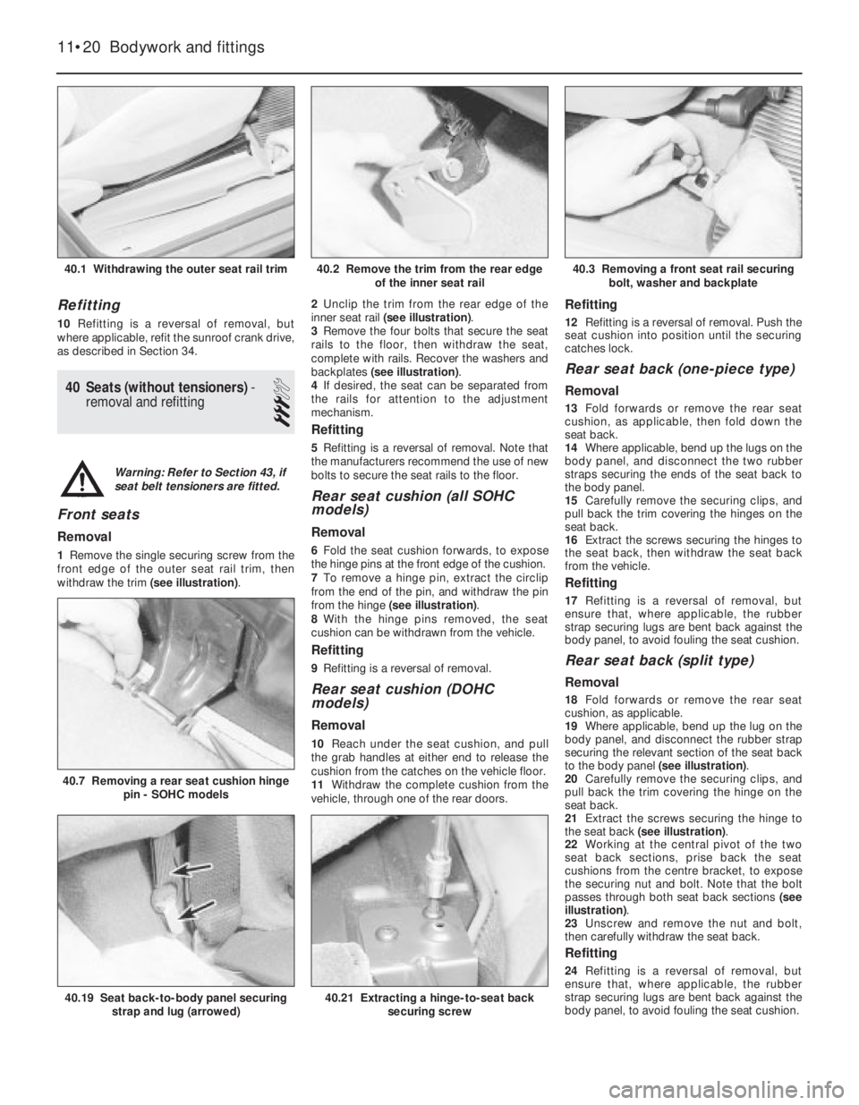
1Remove the single securing screw from the
front edge of the outer seat rail trim, then
withdraw the trim (see illustration).2Unclip the trim from the rear edge of the
inner seat rail (see illustration).
3Remove the four bolts that secure the seat
rails to the floor, then withdraw the seat,
complete with rails. Recover the washers and
backplates (see illustration).
4If desired, the seat can be separated from
the rails for attention to the adjustment
mechanism.
Refitting
5Refitting is a reversal of removal. Note that
the manufacturers recommend the use of new
bolts to secure the seat rails to the floor.
Rear seat cushion (all SOHC
models)
Removal
6Fold the seat cushion forwards, to expose
the hinge pins at the front edge of the cushion.
7To remove a hinge pin, extract the circlip
from the end of the pin, and withdraw the pin
from the hinge (see illustration).
8With the hinge pins removed, the seat
cushion can be withdrawn from the vehicle.
Refitting
9Refitting is a reversal of removal.
Rear seat cushion (DOHC
models)
Removal
10Reach under the seat cushion, and pull
the grab handles at either end to release the
cushion from the catches on the vehicle floor.
11Withdraw the complete cushion from the
vehicle, through one of the rear doors.
Refitting
12Refitting is a reversal of removal. Push the
seat cushion into position until the securing
catches lock.
Rear seat back (one-piece type)
Removal
13Fold forwards or remove the rear seat
cushion, as applicable, then fold down the
seat back.
14Where applicable, bend up the lugs on the
body panel, and disconnect the two rubber
straps securing the ends of the seat back to
the body panel.
15Carefully remove the securing clips, and
pull back the trim covering the hinges on the
seat back.
16Extract the screws securing the hinges to
the seat back, then withdraw the seat back
from the vehicle.
Refitting
17Refitting is a reversal of removal, but
ensure that, where applicable, the rubber
strap securing lugs are bent back against the
body panel, to avoid fouling the seat cushion.
Rear seat back (split type)
Removal
18Fold forwards or remove the rear seat
cushion, as applicable.
19Where applicable, bend up the lug on the
body panel, and disconnect the rubber strap
securing the relevant section of the seat back
to the body panel (see illustration).
20Carefully remove the securing clips, and
pull back the trim covering the hinge on the
seat back.
21Extract the screws securing the hinge to
the seat back (see illustration).
22Working at the central pivot of the two
seat back sections, prise back the seat
cushions from the centre bracket, to expose
the securing nut and bolt. Note that the bolt
passes through both seat back sections (see
illustration).
23Unscrew and remove the nut and bolt,
then carefully withdraw the seat back.
Refitting
24Refitting is a reversal of removal, but
ensure that, where applicable, the rubber
strap securing lugs are bent back against the
body panel, to avoid fouling the seat cushion.
11•20Bodywork and fittings
40.1 Withdrawing the outer seat rail trim40.3 Removing a front seat rail securing
bolt, washer and backplate
40.7 Removing a rear seat cushion hinge
pin - SOHC models
40.21 Extracting a hinge-to-seat back
securing screw40.19 Seat back-to-body panel securing
strap and lug (arrowed)
40.2 Remove the trim from the rear edge
of the inner seat rail
Warning: Refer to Section 43, if
seat belt tensioners are fitted.
Page 124 of 525
41Seat belts - removal and
refitting
3
Note: For details on mechanical seat belt
tensioners, refer to Section 42.
Front seat belt
Removal
1Open both front and rear doors, and prise
the weatherstrips from the edge of the centre
body pillar.
2Prise off the pillar lower trim panel to
expose the inertia reel unit.
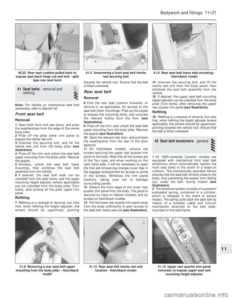
3Unscrew the securing bolt, and tilt the
inertia reel unit from the body pillar (see
illustration).
4Prise off the trim and unbolt the seat belt
upper mounting from the body pillar. Recover
the spacer.
5Similarly, unbolt the seat belt lower
mounting, then withdraw the seat belt
assembly from the vehicle.
6If desired, the seat belt stalk can be
unbolted from the seat frame, and the upper
mounting height adjuster (where applicable)
can be unbolted from the body pillar (Torx
bolts), after prising off the pillar upper trim
panel.
Refitting
7Refitting is a reversal of removal, but note
that, when refitting the height adjuster, the
arrows should be uppermost, pointingtowards the vehicle roof. Ensure that the belt
is fitted untwisted.
Rear seat belt
Removal
8Fold the rear seat cushion forwards, or
remove it, as applicable, for access to the
seat belt lower mountings. Prise up the carpet
to expose the mounting bolts, and unscrew
the relevant bolt(s) from the floor (see
illustrations).
9Prise off the trim, and unbolt the seat belt
upper mounting from the body pillar. Recover
the spacer (see illustration).
10Open the relevant rear door, and pull back
the weatherstrip from the rear of the door
aperture.
11On Hatchback models, remove the
screws securing the upper rear quarter trim
panel to the body. Note that all the screws are
of the Torx type, and when working on the
right-hand side, it will be necessary to open
the first-aid kit/warning triangle cover flap in
the luggage compartment for access to some
of the screws. Withdraw the trim panel
carefully, taking care not to damage
surrounding panels.
12Detach the front edge of the lower rear
quarter trim panel from the body. The panel is
secured by clips on Saloon models, and by
screws on Hatchback models.
13Pull the lower rear quarter trim panel away
from the body sufficiently to gain access to
the seat belt inertia reel unit (see illustration).14Unscrew the securing bolt, and lift the
inertia reel unit from the body panel, then
withdraw the seat belt assembly from the
vehicle.
15If desired, the upper seat belt mounting
height adjuster can be unbolted from the body
pillar (Torx bolts), after removing the upper
rear quarter trim panel (see illustration).
Refitting
16Refitting is a reversal of removal, but note
that, when refitting the height adjuster (where
applicable), the arrows should be uppermost,
pointing towards the vehicle roof. Ensure that
the belt is fitted untwisted.
42Seat belt tensioners - general
5
1All 1993-onwards Cavalier models are
equipped with mechanical front seat belt
tensioners which automatically tighten the
front seat belts in the event of a head-on
collision. The mechanically operated device
ensures that the seat belt remains close to the
body, thus preventing the wearer from sliding
out, under the belt, during impact (see
illustration).
2The tensioner system consists of a powerful
preloaded spring, contained in a cylinder,
which is released in the event of severe
impact. The spring pulls back the seat belt by
means of a bowden cable and fulcrum
mechanism attached to the belt stalk,
mounted on the seat frame.
Bodywork and fittings 11•21
41.8 Rear seat belt lower side mounting -
Hatchback model
41.15 Upper rear quarter trim panel
removed, to expose upper seat belt
mounting height adjuster41.13 Rear seat belt inertia reel unit
location - Hatchback model41.9 Removing a rear seat belt upper
mounting from the body pillar - Hatchback
model
41.3 Unscrewing a front seat belt inertia
reel securing bolt40.22 Rear seat cushion pulled back to
expose seat back hinge nut and bolt - split
type rear seat back
11