change wheel OPEL CASCADA 2015 Manual user
[x] Cancel search | Manufacturer: OPEL, Model Year: 2015, Model line: CASCADA, Model: OPEL CASCADA 2015Pages: 253, PDF Size: 7.58 MB
Page 13 of 253

In brief11
1Power windows .....................32
2 Exterior mirrors .....................30
3 Cruise control .....................151
Speed limiter ....................... 153
Forward collision alert .........154
4 Side air vents ...................... 131
5 Turn and lane-change
signals, headlight flash,
low beam and high beam,
high beam assist .................117
Exit lighting ......................... 121
Parking lights ...................... 118
Buttons for Driver
Information Centre ................96
6 Instruments .......................... 85
7 Steering wheel controls .......78
8 Driver Information Centre ...... 96
9 Windscreen wiper,
windscreen washer
system, headlight washer
system ................................... 80
10 Sport mode ........................ 149
Central locking system ..........22Hazard warning flashers ....117
Control indicator for airbag
deactivation .......................... 90
Control indicator for front
passenger seat belt .............90
Tour mode .......................... 149
11 Info-Display ........................ 100
12 Anti-theft alarm system
status LED ........................... 27
13 Centre air vents .................. 131
14 Glovebox, lockable ...............70
15 Traction Control system .....147
Electronic Stability Control . 148
Parking assist systems .......157
Lane departure warning .....171
Eco button for stop-start
system ................................. 136
16 Climate control system ........ 123
17 AUX input, USB input ..........10
18 Power outlet .......................... 8419Soft top operation switch .....35
Central window switch .........32
20 Selector lever, manual
transmission ....................... 144
Automatic transmission ......141
21 Parking brake, manual or
electric operation ................145
22 Ignition switch with
steering wheel lock ............134
23 Horn ..................................... 79
Driver airbag ........................ 61
24 Bonnet release lever ..........183
25 Storage compartment ..........71
Fuse box ............................ 200
26 Steering wheel adjustment ..78
27 Light switch ........................ 110
Headlight range
adjustment ......................... 113
Front fog lights ...................118
Rear fog light ...................... 118 Instrument illumination .......119
Page 72 of 253

70StorageStorageStorage compartments................70
Load compartment .......................73
Loading information .....................77Storage compartments9Warning
Do not store heavy or sharp
objects in the storage
compartments. Otherwise, the
storage compartment lid could
open and vehicle occupants could be injured by objects being thrown
around in the event of hard
braking, a sudden change in
direction or an accident.
Glovebox
The glovebox features a pen holder,
a credit card holder, a coin holder and
an adapter for the locking wheel nuts.
Close glovebox whilst driving. It can
be locked with the vehicle key.
Page 90 of 253

88Instruments and controls
The remaining oil life duration is
displayed in the Vehicle Information
Menu .
The menu and function can be
selected via the buttons on the turn
signal lever.
To display the remaining engine oil
life duration:
Press the MENU button to select the
Vehicle Information Menu X.
Turn the adjuster wheel to select Remaining Oil Life .
The system must be reset every time
the engine oil is changed to allow
proper functionality. Seek the
assistance of a workshop.
Press the SET/CLR button to reset.
Therefore the ignition must be
switched on, with the engine not
running.
When the system has calculated that
engine oil life has been diminished,
Change Engine Oil Soon appears in
the Driver Information Centre. Have
engine oil and filter changed by a
workshop within one week or
500 km (whichever occurs first).
Driver Information Centre 3 96.
Service information 3 226.
Control indicators The control indicators described are
not present in all vehicles. The
description applies to all instrument
versions. Depending on the
equipment, the position of the control indicators may vary. When theignition is switched on, most control
indicators will illuminate briefly as a
functionality test.
The control indicator colours mean:red=danger, important reminderyellow=warning, information, faultgreen=confirmation of activationblue=confirmation of activationwhite=confirmation of activation
Page 99 of 253
Instruments and controls97
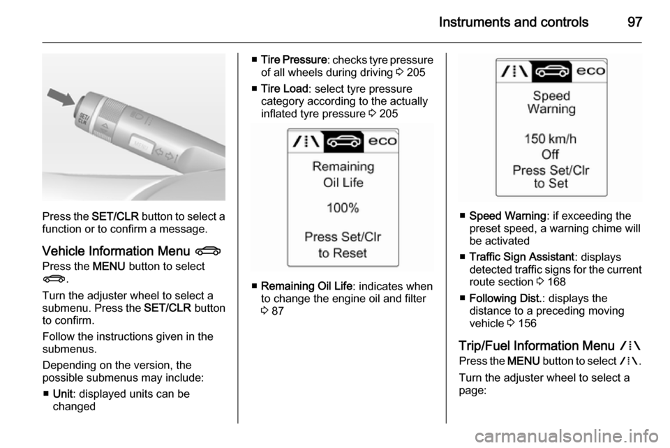
Press the SET/CLR button to select a
function or to confirm a message.
Vehicle Information Menu X
Press the MENU button to select
X .
Turn the adjuster wheel to select a
submenu. Press the SET/CLR button
to confirm.
Follow the instructions given in the
submenus.
Depending on the version, the
possible submenus may include:
■ Unit : displayed units can be
changed
■ Tire Pressure : checks tyre pressure
of all wheels during driving 3 205
■ Tire Load : select tyre pressure
category according to the actually
inflated tyre pressure 3 205
■ Remaining Oil Life : indicates when
to change the engine oil and filter
3 87
■ Speed Warning : if exceeding the
preset speed, a warning chime will
be activated
■ Traffic Sign Assistant : displays
detected traffic signs for the current
route section 3 168
■ Following Dist. : displays the
distance to a preceding moving
vehicle 3 156
Trip/Fuel Information Menu W
Press the MENU button to select W.
Turn the adjuster wheel to select a
page:
Page 104 of 253

102Instruments and controls
Turn multifunction knob to:■ select a setting or value
■ display a menu option
Push multifunction knob to: ■ confirm a setting or value
■ select or activate the marked option
■ switch a system function on/off
Push button BACK to:
■ exit a menu or setting without changing
■ return from a submenu to a higher menu level
■ delete the last character in a character sequence. Push BACK
for a few seconds to delete the
entire entry.
To exit the Settings menu, push
button BACK stepwise or push button
CONFIG after confirming the
changes.
Vehicle personalisation 3 104.
Memorised settings 3 22.
Vehicle messages
Messages are indicated in the Driver
Information Centre (DIC), in some
cases together with a warning and
signal sound.
Press the SET/CLR button, the
MENU button or turn the adjuster
wheel to confirm a message.
Page 119 of 253
Lighting117
Automatic high beam activation
operates at a speed above 40 km/h
and deactivates below 20 km/h.
Intelligent light ranging operates
above 55 km/h.
The green control indicator l
illuminates continuously when the
function is activated, the blue one 7
illuminates when high beam switches on automatically.
Deactivation
Push indicator lever once. It is also deactivated when front fog lights are
switched on.
Dynamic automatic headlight levelling
To prevent oncoming traffic from
dazzle, headlight levelling is
automatically adjusted based on
inclination information measured by
front and rear axle, acceleration or
deceleration and vehicle speed.Fault in Adaptive forward
lighting system When the system detects a failure in
the Adaptive forward lighting system,
the system moves to a preset position
to avoid dazzling of oncoming traffic.
If this is not possible, the affected headlight will be automatically
switched off. In any case, one
headlight will stay on. A warning is
displayed in the Driver Information Centre.
Hazard warning flashers
Operated with the ¨ button.
In the event of an accident with airbag
deployment the hazard warning
flashers are activated automatically.
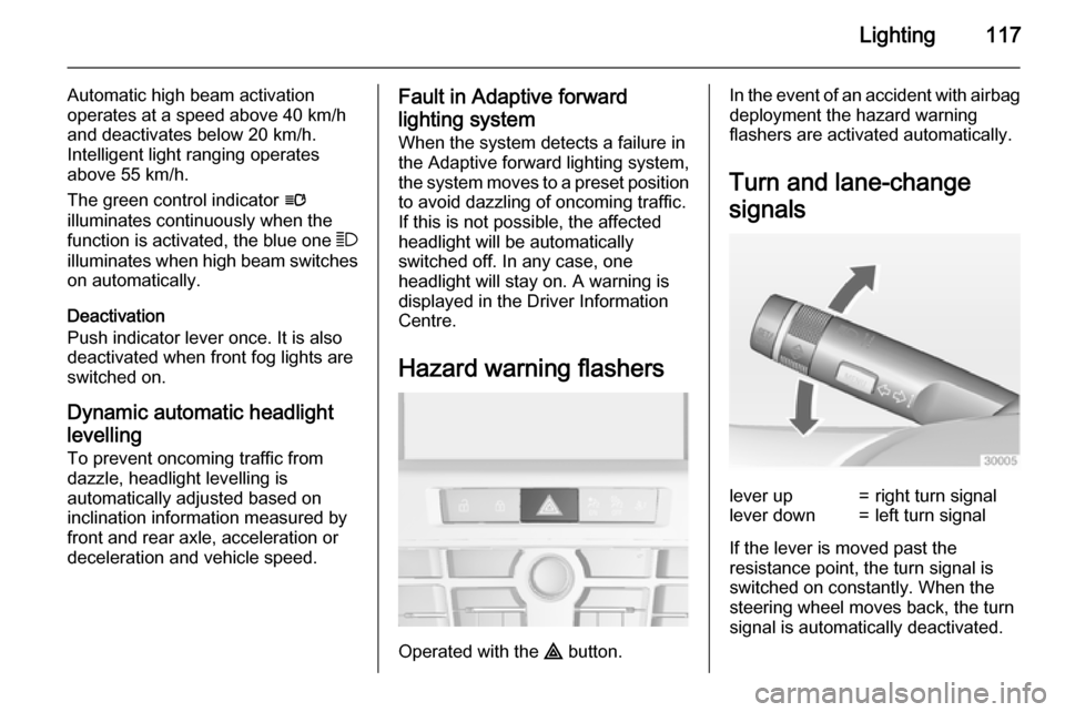
Turn and lane-change
signalslever up=right turn signallever down=left turn signal
If the lever is moved past the
resistance point, the turn signal is
switched on constantly. When the
steering wheel moves back, the turn
signal is automatically deactivated.
Page 129 of 253
Climate control127
Heated rear window Ü 3 34, Heated
seats ß 3 54, Ventilated seats 3 54,
Heated steering wheel * 3 79.
Climate control settings are shown on
the Graphic-Info-Display, or
depending on the version, on Colour- Info-Display. Setting modifications
are briefly popped-up in both
displays, superimposed over the
currently displayed menu.
The electronic climate control system
is only fully operational when the
engine is running.
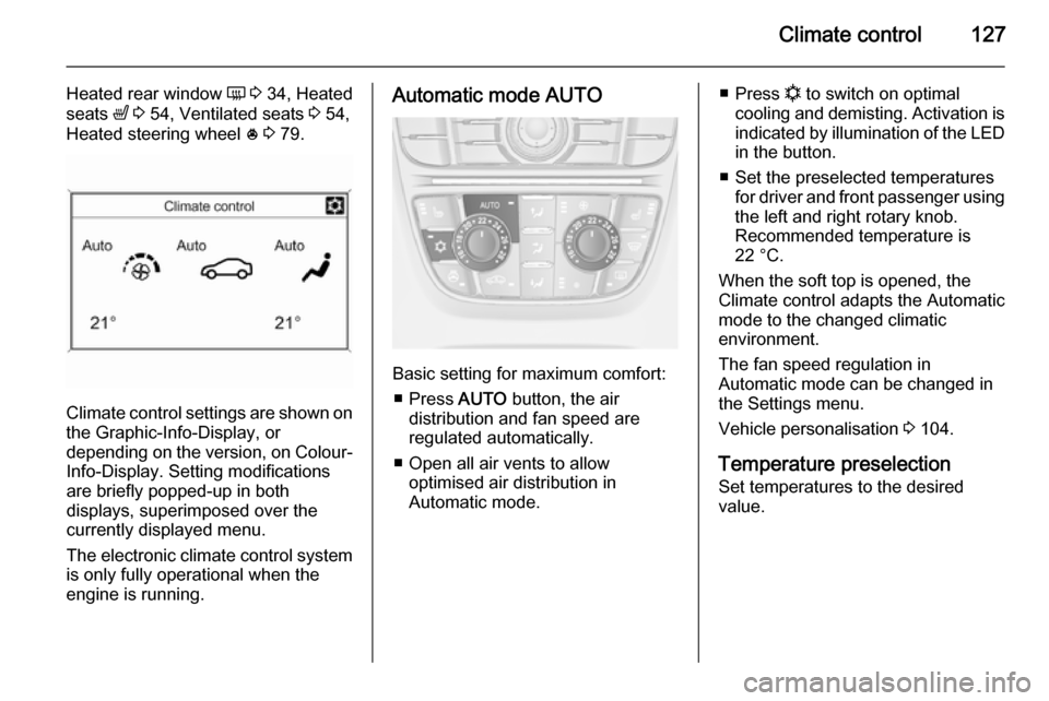
Automatic mode AUTO
Basic setting for maximum comfort:
■ Press AUTO button, the air
distribution and fan speed are
regulated automatically.
■ Open all air vents to allow optimised air distribution in
Automatic mode.
■ Press n to switch on optimal
cooling and demisting. Activation is indicated by illumination of the LED
in the button.
■ Set the preselected temperatures for driver and front passenger using
the left and right rotary knob.
Recommended temperature is
22 °C.
When the soft top is opened, the
Climate control adapts the Automatic
mode to the changed climatic
environment.
The fan speed regulation in
Automatic mode can be changed in
the Settings menu.
Vehicle personalisation 3 104.
Temperature preselection
Set temperatures to the desired
value.
Page 155 of 253
Driving and operating153Speed limiterThe speed limiter prevents the
vehicle exceeding a preset maximum
speed.
The maximum speed can be set at a
speed above 25 km/h.
The driver can only accelerate up to
the preset speed. Deviations from the
limited speed may occur when driving downhill.
The preset speed limit is displayed in
the top line of the Driver Information
Centre when the system is active.
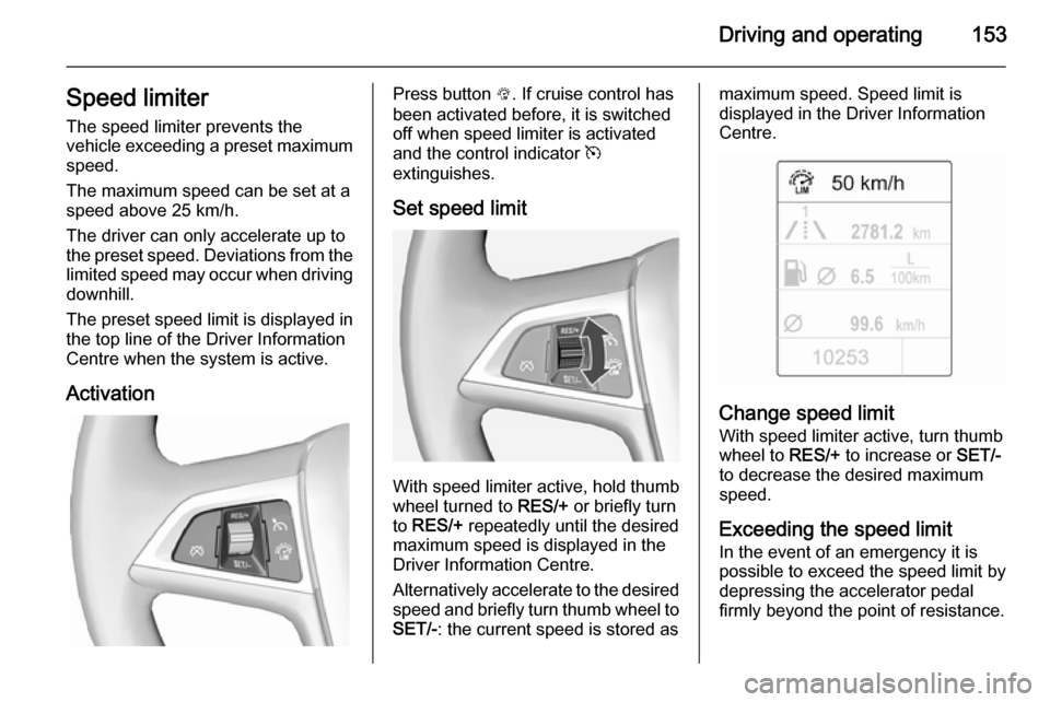
ActivationPress button L. If cruise control has
been activated before, it is switched
off when speed limiter is activated
and the control indicator m
extinguishes.
Set speed limit
With speed limiter active, hold thumb
wheel turned to RES/+ or briefly turn
to RES/+ repeatedly until the desired
maximum speed is displayed in the
Driver Information Centre.
Alternatively accelerate to the desired speed and briefly turn thumb wheel to SET/- : the current speed is stored as
maximum speed. Speed limit is
displayed in the Driver Information
Centre.
Change speed limit
With speed limiter active, turn thumb
wheel to RES/+ to increase or SET/-
to decrease the desired maximum
speed.
Exceeding the speed limit
In the event of an emergency it is possible to exceed the speed limit by
depressing the accelerator pedal
firmly beyond the point of resistance.
Page 183 of 253
Vehicle care181Vehicle careGeneral Information...................181
Vehicle checks ........................... 182
Bulb replacement .......................189
Electrical system ........................197
Vehicle tools .............................. 203
Wheels and tyres .......................204
Jump starting ............................. 219
Towing ....................................... 220
Appearance care .......................222General Information
Accessories and vehicle
modifications
We recommend the use of genuine parts and accessories and factory
approved parts specific for your
vehicle type. We cannot assess or
guarantee reliability of other products
- even if they have a regulatory or
otherwise granted approval.
Do not make any modifications to the electrical system, e.g. changes of
electronic control units (chip tuning).Caution
When transporting the vehicle on
a train or on a recovery vehicle, the
mud flaps might be damaged.
Vehicle storage
Storage for a long period of time
If the vehicle is to be stored for several months:
■ Wash the vehicle. Wax painted parts of the vehicle. Exterior care
3 222.
■ Have the wax in the engine compartment and underbody
checked.
■ Clean and preserve the rubber seals.
■ Fill up fuel tank completely.
■ Change the engine oil.
■ Drain the washer fluid reservoir.
■ Check the coolant antifreeze and corrosion protection.
■ Adjust tyre pressure to the value specified for full load.
■ Park the vehicle in a dry, well ventilated place. Engage first orreverse gear or set selector lever to P . Prevent the vehicle from rolling.
■ Do not apply the parking brake.
Page 215 of 253
Vehicle care213
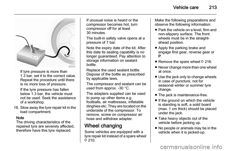
If tyre pressure is more than
1.3 bar , set it to the correct value.
Repeat the procedure until there
is no more loss of pressure.
If the tyre pressure has fallen
below 1.3 bar, the vehicle must
not be used. Seek the assistance
of a workshop.
18. Stow away the tyre repair kit in the
load compartment.
Note
The driving characteristics of the
repaired tyre are severely affected,
therefore have this tyre replaced.
If unusual noise is heard or the
compressor becomes hot, turn
compressor off for at least
30 minutes.
The built-in safety valve opens at a
pressure of 7 bar.
Note the expiry date of the kit. After
this date its sealing capability is no
longer guaranteed. Pay attention to
storage information on sealant
bottle.
Replace the used sealant bottle. Dispose of the bottle as prescribed
by applicable laws.
The compressor and sealant can be
used from approx. -30 °C.
The adapters supplied can be used
to pump up other items e.g.
footballs, air mattresses, inflatable
dinghies etc. They are located on the underside of the compressor. To
remove, screw on compressor air hose and withdraw adapter.
Wheel changing Some vehicles are equipped with a
tyre repair kit instead of a spare wheel 3 210.Make the following preparations and
observe the following information:
■ Park the vehicle on a level, firm and
non-slippery surface. The front wheels must be in the straight-
ahead position.
■ Apply the parking brake and engage first gear, reverse gear or
P .
■ Remove the spare wheel 3 216.
■ Never change more than one wheel
at once.
■ Use the jack only to change wheels
in case of puncture, not for
seasonal winter or summer tyre
change.
■ The jack is maintenance-free.
■ If the ground on which the vehicle is standing is soft, a solid board
(max. 1 cm thick) should be placed
under the jack.
■ Take heavy objects out of the vehicle before jacking up.
■ No people or animals may be in the
vehicle when it is jacked-up.