service indicator OPEL CASCADA 2015 Manual user
[x] Cancel search | Manufacturer: OPEL, Model Year: 2015, Model line: CASCADA, Model: OPEL CASCADA 2015Pages: 253, PDF Size: 7.58 MB
Page 89 of 253

Instruments and controls87Fuel gauge
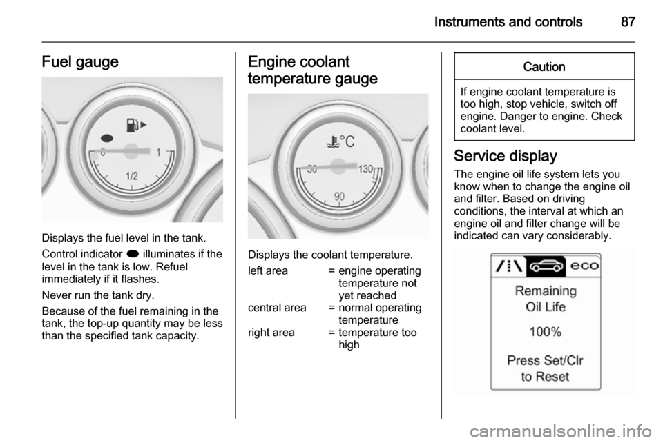
Displays the fuel level in the tank.
Control indicator i illuminates if the
level in the tank is low. Refuel
immediately if it flashes.
Never run the tank dry.
Because of the fuel remaining in the
tank, the top-up quantity may be less
than the specified tank capacity.
Engine coolant
temperature gauge
Displays the coolant temperature.
left area=engine operating
temperature not
yet reachedcentral area=normal operating
temperatureright area=temperature too
highCaution
If engine coolant temperature is
too high, stop vehicle, switch off
engine. Danger to engine. Check
coolant level.
Service display
The engine oil life system lets you
know when to change the engine oil
and filter. Based on driving
conditions, the interval at which an
engine oil and filter change will be
indicated can vary considerably.
Page 90 of 253

88Instruments and controls
The remaining oil life duration is
displayed in the Vehicle Information
Menu .
The menu and function can be
selected via the buttons on the turn
signal lever.
To display the remaining engine oil
life duration:
Press the MENU button to select the
Vehicle Information Menu X.
Turn the adjuster wheel to select Remaining Oil Life .
The system must be reset every time
the engine oil is changed to allow
proper functionality. Seek the
assistance of a workshop.
Press the SET/CLR button to reset.
Therefore the ignition must be
switched on, with the engine not
running.
When the system has calculated that
engine oil life has been diminished,
Change Engine Oil Soon appears in
the Driver Information Centre. Have
engine oil and filter changed by a
workshop within one week or
500 km (whichever occurs first).
Driver Information Centre 3 96.
Service information 3 226.
Control indicators The control indicators described are
not present in all vehicles. The
description applies to all instrument
versions. Depending on the
equipment, the position of the control indicators may vary. When theignition is switched on, most control
indicators will illuminate briefly as a
functionality test.
The control indicator colours mean:red=danger, important reminderyellow=warning, information, faultgreen=confirmation of activationblue=confirmation of activationwhite=confirmation of activation
Page 94 of 253

92Instruments and controls
Illuminates
Brake pedal must be depressed to release the electric parking brake
3 145.
Clutch pedal must be depressed to
start the engine in Autostop mode.
Stop-start system 3 136.
Flashes Clutch pedal must be depressed for amain start of the engine 3 17, 3 135.
On some versions, the operate pedal
message is indicated in the Driver
Information Display 3 102.
Electric parking brake
m illuminates or flashes red.
Illuminates Electric parking brake is applied
3 145.Flashes
Electric parking brake is not fullyapplied or released. Switch on
ignition, depress brake pedal and
attempt to reset the system by first
releasing and then applying the
electric parking brake. If m remains
flashing, do not drive and seek the
assistance of a workshop.
Electric parking brake fault
j illuminates or flashes yellow.
Illuminates
Electric parking brake is operating
with degraded performance 3 145.
Flashes Electric parking brake is in service
mode. Stop vehicle, apply and
release the electric parking brake to
reset.9 Warning
Have the cause of the fault
remedied immediately by a
workshop.
Antilock brake system
(ABS) u illuminates yellow.
Illuminates for a few seconds after the ignition is switched on. The system is
ready for operation when the control
indicator extinguishes.
If the control indicator does not
extinguish after a few seconds, or if it illuminates while driving, there is a
fault in the ABS. The brake system
remains operational but without ABS
regulation.
Antilock brake system 3 144.
Page 137 of 253

Driving and operating135
■ Power windows
■ Power outlets
Power to the Infotainment system will continue to operate for 30 minutes oruntil the key is removed from theignition switch, regardless of whether
any door will be opened.
Starting the engine
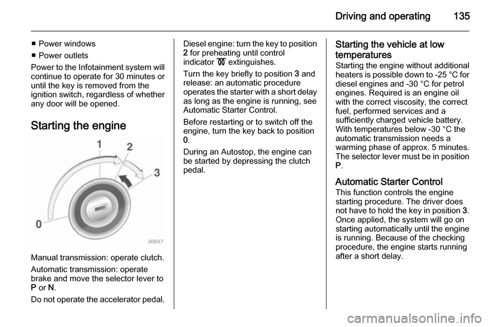
Manual transmission: operate clutch.
Automatic transmission: operate
brake and move the selector lever to
P or N.
Do not operate the accelerator pedal.
Diesel engine: turn the key to position 2 for preheating until control
indicator ! extinguishes.
Turn the key briefly to position 3 and
release: an automatic procedure
operates the starter with a short delay
as long as the engine is running, see
Automatic Starter Control.
Before restarting or to switch off the
engine, turn the key back to position
0 .
During an Autostop, the engine can
be started by depressing the clutch
pedal.Starting the vehicle at low
temperatures
Starting the engine without additional heaters is possible down to -25 °С for
diesel engines and -30 °C for petrol
engines. Required is an engine oil
with the correct viscosity, the correct
fuel, performed services and a
sufficiently charged vehicle battery.
With temperatures below -30 °C the
automatic transmission needs a
warming phase of approx. 5 minutes.
The selector lever must be in position P .
Automatic Starter Control
This function controls the engine
starting procedure. The driver does
not have to hold the key in position 3.
Once applied, the system will go on starting automatically until the engine
is running. Because of the checking
procedure, the engine starts running after a short delay.
Page 209 of 253

Vehicle care207
If w illuminates at lower temperatures
and extinguishes after some driving,
this could be an indicator for getting
low pressure. Check tyre pressure.
Vehicle messages 3 102.
If the tyre pressure must be reduced
or increased, switch off ignition.
Only mount wheels with pressure
sensors, otherwise the tyre pressure
will not be displayed and w
illuminates continuously.
A temporary spare wheel is not
equipped with pressure sensors. The
tyre pressure monitoring system is
not operational for these wheels.
Control indicator w illuminates. For
the further three wheels the system
remains operational.
The use of commercially available
liquid tyre repair kits can impair the
function of the system. Factory-
approved repair kits can be used.
External high-power radio equipment
could disrupt the tyre pressure
monitoring system.Each time the tyres are replaced, tyre pressure monitoring system sensors
must be dismounted and serviced.
For the screwed sensor: replace
valve core and sealing ring. For
clipped sensor: replace complete
valve stem.
Vehicle loading status Adjust tyre pressure to load condition according to tyre information label or
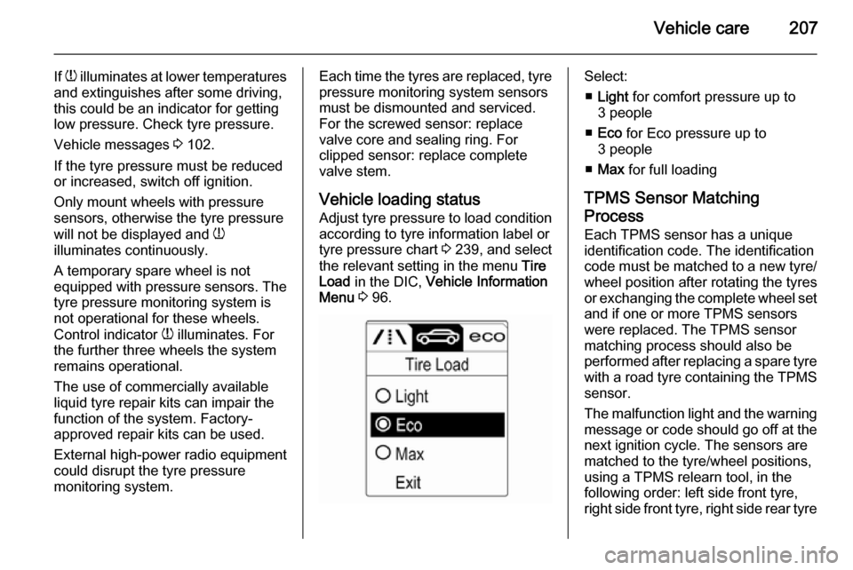
tyre pressure chart 3 239, and select
the relevant setting in the menu Tire
Load in the DIC, Vehicle Information
Menu 3 96.Select:
■ Light for comfort pressure up to
3 people
■ Eco for Eco pressure up to
3 people
■ Max for full loading
TPMS Sensor Matching
Process
Each TPMS sensor has a unique
identification code. The identification
code must be matched to a new tyre/
wheel position after rotating the tyres
or exchanging the complete wheel set and if one or more TPMS sensors
were replaced. The TPMS sensor matching process should also be
performed after replacing a spare tyre
with a road tyre containing the TPMS
sensor.
The malfunction light and the warning
message or code should go off at the
next ignition cycle. The sensors are
matched to the tyre/wheel positions,
using a TPMS relearn tool, in the
following order: left side front tyre,
right side front tyre, right side rear tyre