tow bar OPEL CASCADA 2015 Manual user
[x] Cancel search | Manufacturer: OPEL, Model Year: 2015, Model line: CASCADA, Model: OPEL CASCADA 2015Pages: 253, PDF Size: 7.58 MB
Page 46 of 253
44Keys, doors and windows
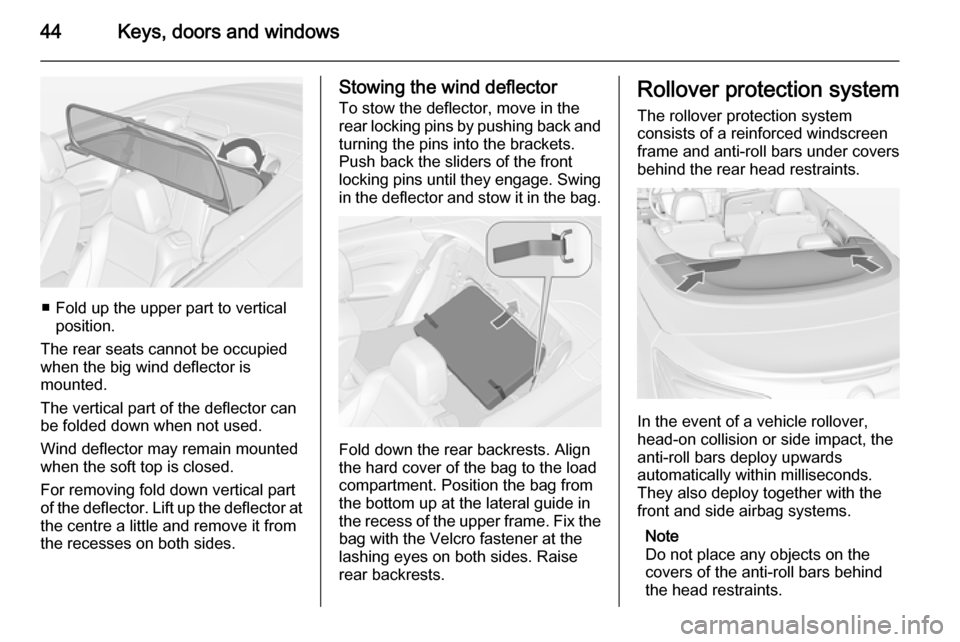
■ Fold up the upper part to verticalposition.
The rear seats cannot be occupied
when the big wind deflector is
mounted.
The vertical part of the deflector can
be folded down when not used.
Wind deflector may remain mounted
when the soft top is closed.
For removing fold down vertical part
of the deflector. Lift up the deflector at
the centre a little and remove it from
the recesses on both sides.
Stowing the wind deflector
To stow the deflector, move in the
rear locking pins by pushing back and
turning the pins into the brackets.
Push back the sliders of the front
locking pins until they engage. Swing in the deflector and stow it in the bag.
Fold down the rear backrests. Align
the hard cover of the bag to the load
compartment. Position the bag from
the bottom up at the lateral guide in
the recess of the upper frame. Fix the
bag with the Velcro fastener at the
lashing eyes on both sides. Raise
rear backrests.
Rollover protection system
The rollover protection system
consists of a reinforced windscreen
frame and anti-roll bars under covers
behind the rear head restraints.
In the event of a vehicle rollover,
head-on collision or side impact, the
anti-roll bars deploy upwards
automatically within milliseconds.
They also deploy together with the
front and side airbag systems.
Note
Do not place any objects on the
covers of the anti-roll bars behind
the head restraints.
Page 61 of 253

Seats, restraints59
geschützt ist, da dies den TOD oder
SCHWERE VERLETZUNGEN DES
KINDES zur Folge haben kann.
FR: NE JAMAIS utiliser un siège
d'enfant orienté vers l'arrière sur un
siège protégé par un COUSSIN
GONFLABLE ACTIF placé devant lui,
sous peine d'infliger des
BLESSURES GRAVES, voire
MORTELLES à l'ENFANT.
ES: NUNCA utilice un sistema de
retención infantil orientado hacia
atrás en un asiento protegido por un AIRBAG FRONTAL ACTIVO. Peligro de MUERTE o LESIONES GRAVES
para el NIÑO.
RU: ЗАПРЕЩАЕТСЯ
устанавливать детское
удерживающее устройство лицом
назад на сиденье автомобиля,
оборудованном фронтальной
подушкой безопасности, если
ПОДУШКА НЕ ОТКЛЮЧЕНА! Это
может привести к СМЕРТИ или
СЕРЬЕЗНЫМ ТРАВМАМ
РЕБЕНКА.NL: Gebruik NOOIT een achterwaarts
gericht kinderzitje op een stoel met
een ACTIEVE AIRBAG ervoor, om
DODELIJK of ERNSTIG LETSEL van
het KIND te voorkomen.
DA: Brug ALDRIG en bagudvendt
autostol på et forsæde med AKTIV
AIRBAG, BARNET kan komme i
LIVSFARE eller komme ALVORLIGT TIL SKADE.
SV: Använd ALDRIG en bakåtvänd
barnstol på ett säte som skyddas med en framförvarande AKTIV AIRBAG.
DÖDSFALL eller ALLVARLIGA
SKADOR kan drabba BARNET.
FI: ÄLÄ KOSKAAN sijoita taaksepäin
suunnattua lasten turvaistuinta
istuimelle, jonka edessä on
AKTIIVINEN TURVATYYNY, LAPSI
VOI KUOLLA tai VAMMAUTUA
VAKAVASTI.
NO: Bakovervendt
barnesikringsutstyr må ALDRI brukes på et sete med AKTIV
KOLLISJONSPUTE foran, da det kan
føre til at BARNET utsettes for
LIVSFARE og fare for ALVORLIGE
SKADER.PT: NUNCA use um sistema de
retenção para crianças voltado para
trás num banco protegido com um
AIRBAG ACTIVO na frente do
mesmo, poderá ocorrer a PERDA DE
VIDA ou FERIMENTOS GRAVES na CRIANÇA.
IT: Non usare mai un sistema di
sicurezza per bambini rivolto
all'indietro su un sedile protetto da
AIRBAG ATTIVO di fronte ad esso:
pericolo di MORTE o LESIONI
GRAVI per il BAMBINO!
EL: ΠΟΤΕ μη χρησιμοποιείτε παιδικό
κάθισμα ασφαλείας με φορά προς τα
πίσω σε κάθισμα που προστατεύεται
από μετωπικό ΕΝΕΡΓΟ ΑΕΡΟΣΑΚΟ,
διότι το παιδί μπορεί να υποστεί
ΘΑΝΑΣΙΜΟ ή ΣΟΒΑΡΟ
ΤΡΑΥΜΑΤΙΣΜΟ.
PL: NIE WOLNO montować fotelika
dziecięcego zwróconego tyłem do
kierunku jazdy na fotelu, przed
którym znajduje się WŁĄCZONA
PODUSZKA POWIETRZNA.
Niezastosowanie się do tego
Page 79 of 253

Storage77Loading information■ Heavy objects in the load compartment should be placed as
far forward as possible. Ensure that
the backrests are securely
engaged. If objects can be stacked, heavier objects should be placed at the bottom.
■ Secure objects with lashing straps attached to the lashing eyes 3 76.
■ Use the hooks in the load compartment for hanging up carrier
bags 3 75 . Maximum load: 5 kg per
hook.
■ Secure loose objects in the load compartment to prevent them from
sliding.
■ When transporting objects in the load compartment, the backrests ofthe rear seats must not be angled
forward.
■ Do not place any objects on the instrument panel, and do not cover
the sensor on top of the instrument
panel.■ The load must not obstruct the operation of the pedals, parking
brake and gear selector lever, or
hinder the freedom of movement of the driver. Do not place any
unsecured objects in the interior.
■ Do not place any objects on the covers of the anti-roll bars behind
the head restraints.
■ Do not drive with an open load compartment.9 Warning
Always make sure that the load in
the vehicle is securely stowed.
Otherwise objects can be thrown
around inside the vehicle and
cause personal injury or damage
to the load or car.
■ The payload is the difference between the permitted gross
vehicle weight (see identification
plate 3 229) and the EC kerb
weight.
To calculate the payload, enter the
data for your vehicle in the Weights
table at the front of this manual.
The EC kerb weight includes
weights for the driver (68 kg),
luggage (7 kg) and all fluids (tank
90 % full).
Optional equipment and
accessories increase the kerb
weight.
Page 177 of 253

Driving and operating175
applicable version), taking into
consideration the vehicle weight in running order, as specified by the
regulation.
The figures are provided only for the
purpose of comparison between
different vehicle variants and must
not be taken as a guarantee for the
actual fuel consumption of a
particular vehicle. Additional
equipment may result in slightly
higher results than the stated
consumption and CO 2 figures.
Furthermore, fuel consumption is dependent on personal driving style
as well as road and traffic conditions.Trailer hitch
General information
Only use towing equipment that has
been approved for your vehicle.
Entrust retrofitting of towing
equipment to a workshop. It may be
necessary to make changes that
affect the cooling system, heat
shields or other equipment.
The bulb outage detection function for
trailer brake light cannot detect a
partial bulb outage, e.g. in case of 4 x
5 Watt bulbs, the function only detects lamp outage when only a single
5 Watt lamp remains or none remain.
Fitting of towing equipment could
cover the opening of the towing eye.
If this is the case use the coupling ball
bar for towing. Always keep the
coupling ball bar in the vehicle.Driving characteristics and
towing tips
Before attaching a trailer, lubricate
the coupling ball. However, do not do
so if a stabiliser, which acts on the coupling ball, is being used to reduce snaking movements.
For trailers with low driving stability
and caravan trailers with a permitted
gross vehicle weight of more than
1200 kg the use of a stabiliser is
strongly recommended when driving
above 80 km/h.
If the trailer starts snaking, drive more slowly, do not attempt to correct the
steering and brake sharply if
necessary.
When driving downhill, drive in the
same gear as if driving uphill and
drive at a similar speed.
Adjust tyre pressure to the value
specified for full load 3 239.
Page 178 of 253

176Driving and operatingTrailer towingTrailer loads
The permissible trailer loads are
vehicle and engine-dependent
maximum values which must not be
exceeded. The actual trailer load is
the difference between the actual
gross weight of the trailer and the
actual coupling socket load with the
trailer coupled.
The permissible trailer loads are
specified in the vehicle documents. In
general, they are valid for gradients
up to max. 12 %.
The permitted trailer load applies up
to the specified incline and up to an
altitude of 1000 metres above sea
level. Since engine power decreases
as altitude increases due to the air
becoming thinner, therefore reducing
climbing ability, the permissible gross train weight also decreases by 10 %
for every 1000 metres of additional
altitude. The gross train weight does
not have to be reduced when driving
on roads with slight inclines (less than
8 %, e.g. motorways).The permissible gross train weight
must not be exceeded. This weight is
specified on the identification plate
3 229.
Vertical coupling load
The vertical coupling load is the load
exerted by the trailer on the coupling
ball. It can be varied by changing the
weight distribution when loading the
trailer.
The maximum permissible vertical
coupling load (75 kg) is specified on
the towing equipment identification
plate and in the vehicle documents.
Always aim for the maximum load,
especially in the case of heavy
trailers. The vertical coupling load
should never fall below 25 kg.Rear axle load
When the trailer is coupled and the
towing vehicle fully loaded, the
permissible rear axle load (see
identification plate or vehicle
documents) may be exceeded by
100 kg, the gross vehicle weight
rating may be exceeded by 100 kg. If
the permissible rear axle load is
exceeded, a maximum speed of
100 km/h applies.
Towing equipmentCaution
When operating without a trailer,
remove the coupling ball bar.
Stowage of coupling ball bar
The coupling ball bar is stowed in a
bag and must be secured in the load
compartment.
Page 179 of 253
Driving and operating177
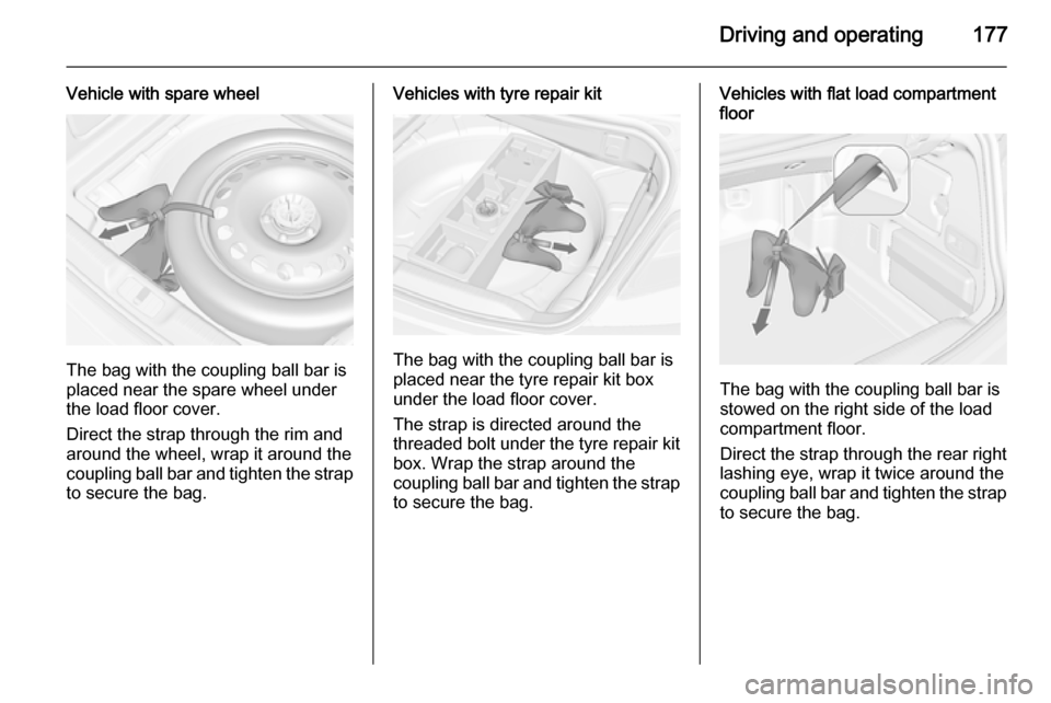
Vehicle with spare wheel
The bag with the coupling ball bar is
placed near the spare wheel under
the load floor cover.
Direct the strap through the rim and around the wheel, wrap it around the
coupling ball bar and tighten the strap
to secure the bag.
Vehicles with tyre repair kit
The bag with the coupling ball bar is
placed near the tyre repair kit box
under the load floor cover.
The strap is directed around the
threaded bolt under the tyre repair kit box. Wrap the strap around the
coupling ball bar and tighten the strap
to secure the bag.
Vehicles with flat load compartment
floor
The bag with the coupling ball bar is
stowed on the right side of the load
compartment floor.
Direct the strap through the rear right
lashing eye, wrap it twice around the
coupling ball bar and tighten the strap
to secure the bag.
Page 180 of 253
178Driving and operating
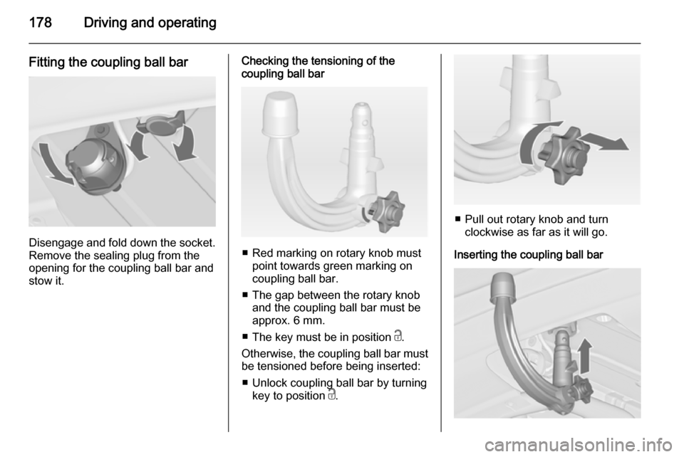
Fitting the coupling ball bar
Disengage and fold down the socket.Remove the sealing plug from the
opening for the coupling ball bar and
stow it.
Checking the tensioning of the
coupling ball bar
■ Red marking on rotary knob must
point towards green marking on
coupling ball bar.
■ The gap between the rotary knob and the coupling ball bar must beapprox. 6 mm.
■ The key must be in position c.
Otherwise, the coupling ball bar must be tensioned before being inserted:
■ Unlock coupling ball bar by turning key to position c.
■ Pull out rotary knob and turn
clockwise as far as it will go.
Inserting the coupling ball bar
Page 181 of 253
Driving and operating179
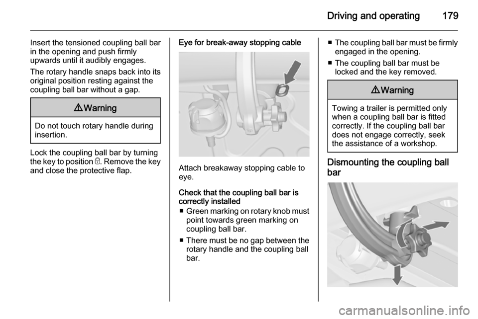
Insert the tensioned coupling ball bar
in the opening and push firmly
upwards until it audibly engages.
The rotary handle snaps back into its
original position resting against the
coupling ball bar without a gap.9 Warning
Do not touch rotary handle during
insertion.
Lock the coupling ball bar by turning
the key to position e. Remove the key
and close the protective flap.
Eye for break-away stopping cable
Attach breakaway stopping cable to
eye.
Check that the coupling ball bar is correctly installed
■ Green marking on rotary knob must
point towards green marking on
coupling ball bar.
■ There must be no gap between the
rotary handle and the coupling ball
bar.
■ The coupling ball bar must be firmly
engaged in the opening.
■ The coupling ball bar must be locked and the key removed.9 Warning
Towing a trailer is permitted only
when a coupling ball bar is fitted correctly. If the coupling ball bardoes not engage correctly, seekthe assistance of a workshop.
Dismounting the coupling ball
bar
Page 182 of 253

180Driving and operating
Open the protective flap and turn the
key to position c to unlock the
coupling ball bar.
Pull out rotary handle and turn
clockwise as far as it will go. Pull out coupling ball bar downwards.
Insert sealing plug in opening. Fold away socket.
Stow and secure the coupling ball bar
as mentioned above.
Page 214 of 253
212Vehicle care
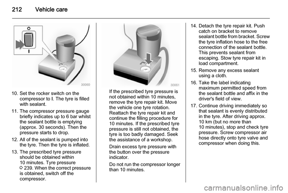
10. Set the rocker switch on thecompressor to I. The tyre is filled
with sealant.
11. The compressor pressure gauge briefly indicates up to 6 bar whilstthe sealant bottle is emptying
(approx. 30 seconds). Then the
pressure starts to drop.
12. All of the sealant is pumped into the tyre. Then the tyre is inflated.
13. The prescribed tyre pressure should be obtained within
10 minutes. Tyre pressure
3 239 . When the correct pressure
is obtained, switch off the
compressor.If the prescribed tyre pressure is
not obtained within 10 minutes,
remove the tyre repair kit. Move
the vehicle one tyre rotation.
Reattach the tyre repair kit and
continue the filling procedure for 10 minutes. If the prescribed tyre
pressure is still not obtained, the
tyre is too badly damaged. Seek
the assistance of a workshop.
Drain excess tyre pressure with
the button over the pressure indicator.
Do not run the compressor longer than 10 minutes.
14. Detach the tyre repair kit. Push catch on bracket to remove
sealant bottle from bracket. Screw
the tyre inflation hose to the free
connection of the sealant bottle.
This prevents sealant from
escaping. Stow tyre repair kit in
load compartment.
15. Remove any excess sealant using a cloth.
16. Take the label indicating maximum permitted speed from
the sealant bottle and affix in the
driver's field of view.
17. Continue driving immediately so that sealant is evenly distributedin the tyre. After driving approx.
10 km (but no more than
10 minutes), stop and check tyre
pressure. Screw compressor air
hose directly onto tyre valve and
compressor when doing this.