ECU OPEL COMBO E 2020 Owner's Guide
[x] Cancel search | Manufacturer: OPEL, Model Year: 2020, Model line: COMBO E, Model: OPEL COMBO E 2020Pages: 283, PDF Size: 29.4 MB
Page 124 of 283

122Instruments and controlsDriver’s attention warning:
Activates or deactivates the
driver drowsiness system.Telematics services
Opel Connect
Opel Connect is a new way to stay
connected and secure on the road.
Features available with
Opel Connect are:
● emergency call function
● breakdown call function
When the vehicle is equipped with
Opel Connect, these features are
automatically activated. Terms and
Conditions apply.
Opel Connect is operated by the
buttons in the overhead console.
Note
Opel Connect is not available for all
markets. For further information,
contact your workshop.
Emergency call function
Vehicles featuring the emergency call
function are equipped with a red SOS button in the overhead console.
The emergency call function will
establish a connection to the nearest
public safety answering point (PSAP).A minimum set of data including
vehicle and location information will
be sent to the PSAP.
Note
Establishing an emergency call may
not be possible in areas without
sufficient network availability or due
to hardware damage during an
accident.
Automatic crash notification
In case of an accident with airbag
deployment, an automatic
emergency call is established and an automatic crash notification will be
transmitted to the next public safety answering point.
Emergency assistance
In case of an emergency you can also
manually place an emergency call by
pressing the red SOS button for more
than two seconds. The LED flashes to confirm that a connection to the
nearest PSAP is being established.
The LED illuminates steadily as long
as the call is active.
Pressing the SOS button immediately
a second time will terminate the call.
The LED switches off.
Page 162 of 283
160Driving and operatingPull right paddle + to shift to a higher
gear.
Pull left paddle - to shift to a lower
gear.
Multiple pulls allow gears to be
skipped.
The selected gear is indicated in the
instrument cluster.
If a higher gear is selected when
vehicle speed is too low, or a lower
gear when vehicle speed is too high,
the shift is not executed. This can
cause a message in the Driver
Information Centre.
In manual mode, no automatic
shifting to a higher gear takes place
at high engine revolutions.
Gear shift indication
The symbol R or S with a number
beside it is indicated when
gearshifting is recommended for fuel
saving reasons.
Shift indication appears only in
manual mode.Electronic driving
programmes
● Following a cold start, the operating temperature
programme increases engine
speed to quickly bring the
catalytic converter to the required
temperature.
● Special programmes automatically adapt the shifting
points when driving up inclines or
down hills.
● In snowy or icy conditions or on other slippery surfaces, the
electronic transmission control
enables the driver to select
manually first, second or third
gear for starting off.
Kickdown Pressing down the accelerator pedal
beyond the kickdown detent will lead to maximum acceleration
independent of selected driving
mode. The transmission shifts to a
lower gear depending on engine
speed.Fault
In the event of a fault a message is
displayed in the Driver Information Centre.
Vehicle messages 3 117.
Electronic transmission control
enables only third gear. The
transmission no longer shifts
automatically.
Do not drive faster than 100 km/h.
Have the cause of the fault remedied by a workshop.
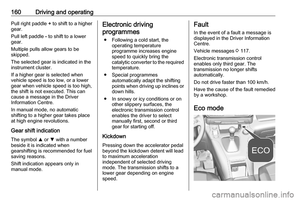
Eco mode
Page 209 of 283
Driving and operating207application of the special servicingconditions referred to as "Arduous
conditions".
For more information, contact a
dealer or a qualified workshop.Caution
The use of any other type of (bio)
fuel (vegetable or animal oils, pure
or diluted, domestic fuel etc.) is
strictly prohibited (risk of damage
to the engine and fuel system).
Note
The only diesel additives authorised for use are those that meet the
B715000 standard.
Vehicles with diesel engine operating
in Ecuador require the additive
DLP 32-600 to avoid damage of the
injection system. This additive can
only be purchased at Opel dealers.
The additive has to be poured into the
tank before refilling Diesel. For each
50 litres of Diesel refilled, 30 millilitres of additive have to be added. To dose
the additive, use the cap of the
additive can. The cap allows a dose
of 30 millilitres.
Low temperature operation At temperatures below 0 °C, somediesel products with biodiesel blendsmay clog, freeze or gel, which may
affect the fuel supply system. Starting
and engine operation may not work
properly. Make sure to fill winter
grade diesel fuel at ambient
temperatures below 0 °C.
Arctic grade diesel fuel can be used
in extreme cold temperatures below
-20 °C. Using this fuel grade in warm
or hot climates is not recommended
and may cause engine stalling, poor starting or damage on the fuel
injection system.
Refuelling9 Danger
Before refuelling, switch off
ignition and any external heaters
with combustion chambers.
Follow the operating and safety
instructions of the filling station
when refuelling.9 Danger
Fuel is flammable and explosive.
No smoking. No naked flames or
sparks.
If you can smell fuel in your
vehicle, have the cause of this
remedied immediately by a
workshop.
A label with symbols at the fuel filler
flap is indicating the allowed fuel
types. In Europe the pump nozzles of the filling stations are marked with
these symbols. Refuel only the
allowed fuel type.
Caution
In case of misfuelling, do not
switch on ignition.
Fuel filler flap is located at left rear
side of vehicle.
Page 213 of 283

Driving and operating2113. Insert the coupling ball bar in theopening and push firmly up to the
stop.
Secure the coupling ball bar
correctly by moving the lever to
the locked position, shown in the
picture.
4. Lock the coupling ball bar by turning the key. Remove the key
and close the protective flap.
5. Attach the trailer.
6. Fold the socket forward.
7. Connect the trailer plug to the socket.
8. Attach the breakaway stoppingcable to the eye on the carrier.
9 Warning
Towing a trailer is permitted only
when a coupling ball bar is fitted correctly. If the coupling ball bardoes not engage correctly, seekthe assistance of a workshop.
Dismounting coupling ball bar
1. Disconnect the trailer plug.
2. Unfasten the breakaway stopping
cable.
3. Remove the trailer.
4. Open the protective flap and unlock the coupling ball bar with
the key.
5. Move the lever of the coupling ball
bar to the rear position. Remove
the coupling ball bar by pulling it.
Page 219 of 283
Vehicle care217
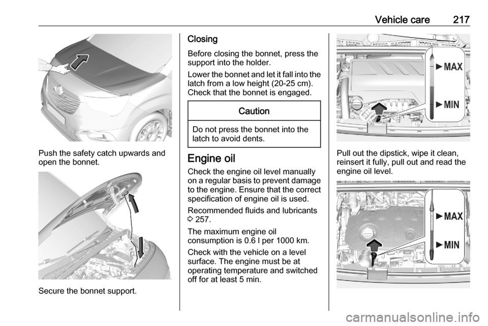
Push the safety catch upwards and
open the bonnet.
Secure the bonnet support.
Closing
Before closing the bonnet, press the
support into the holder.
Lower the bonnet and let it fall into the
latch from a low height (20-25 cm).
Check that the bonnet is engaged.Caution
Do not press the bonnet into the
latch to avoid dents.
Engine oil
Check the engine oil level manually
on a regular basis to prevent damage
to the engine. Ensure that the correct
specification of engine oil is used.
Recommended fluids and lubricants
3 257.
The maximum engine oil
consumption is 0.6 l per 1000 km.
Check with the vehicle on a level
surface. The engine must be at
operating temperature and switched
off for at least 5 min.Pull out the dipstick, wipe it clean,
reinsert it fully, pull out and read the
engine oil level.
Page 246 of 283
244Vehicle care●If necessary, place a chock under
the wheel diagonally opposite the
wheel to be changed.
● Apply the parking brake and engage first gear, reverse gear or
P .
● Remove the spare wheel 3 242.
● Never change more than one wheel at once.
● Use the jack only to change wheels in case of puncture, not
for seasonal winter or summer
tyre change.
● The jack is maintenance-free.
● If the ground on which the vehicle
is standing is soft, a solid board
(max. 1 cm thick) should be
placed under the jack.
● Take heavy objects out of the vehicle before jacking up.
● No people or animals may be in the vehicle when it is jacked-up.
● Never crawl under a jacked-up vehicle.
● Do not start the vehicle when it is
raised on the jack.● Before screwing in the wheel bolts, clean them.9Warning
Do not grease wheel bolts.
9Warning
Ensure to use always the correct
wheel bolts if changing the
wheels. When installing the spare
wheel, the bolts for alloy wheels can also be used.
● Note that the spare wheel is secured by the conical contact ofeach bolt if the wheel bolts for the
alloy wheels are used. In this
case, the washers do not come
into contact with the spare wheel.
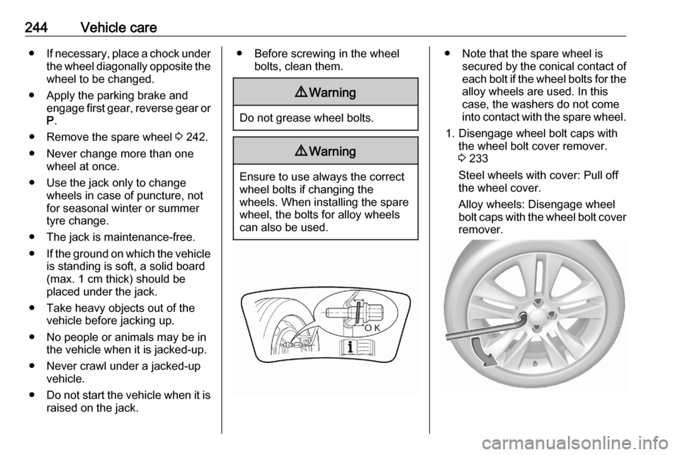
1. Disengage wheel bolt caps with the wheel bolt cover remover.
3 233
Steel wheels with cover: Pull off
the wheel cover.
Alloy wheels: Disengage wheel
bolt caps with the wheel bolt cover remover.
Page 247 of 283
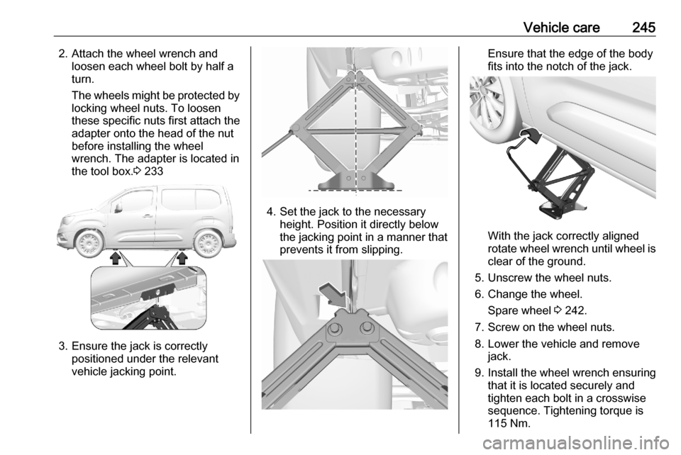
Vehicle care2452. Attach the wheel wrench andloosen each wheel bolt by half a
turn.
The wheels might be protected by locking wheel nuts. To loosen
these specific nuts first attach the
adapter onto the head of the nut
before installing the wheel
wrench. The adapter is located in
the tool box. 3 233
3. Ensure the jack is correctly
positioned under the relevant
vehicle jacking point.
4. Set the jack to the necessary height. Position it directly below
the jacking point in a manner that
prevents it from slipping.
Ensure that the edge of the body
fits into the notch of the jack.
With the jack correctly aligned
rotate wheel wrench until wheel is
clear of the ground.
5. Unscrew the wheel nuts.
6. Change the wheel. Spare wheel 3 242.
7. Screw on the wheel nuts.
8. Lower the vehicle and remove jack.
9. Install the wheel wrench ensuring that it is located securely and
tighten each bolt in a crosswise
sequence. Tightening torque is
115 Nm.
Page 248 of 283
246Vehicle careIf the vehicle is equipped with
alloy wheels, note that the wheel
bolts can also be used for the steel spare wheel. In this case, the
spare wheel is secured by the
conical contact of each bolt.
10. Align the valve hole in the wheel cover with the tyre valve before
installing.
Install wheel nut caps.
11. Stow the replaced wheel 3 242,
the vehicle tools 3 233 and the
adapter for the locking wheel nuts.
12. Check the tyre pressure of the installed tyre and the wheel nut
torque as soon as possible.Jump starting
Do not start with quick charger.
A vehicle with a discharged vehicle
battery can be started using jump
leads and the vehicle battery of
another vehicle.9 Warning
Be extremely careful when starting
with jump leads. Any deviation
from the following instructions can
lead to injuries or damage caused
by battery explosion or damage to the electrical systems of both
vehicles.
9 Warning
Avoid contact of the battery with
eyes, skin, fabrics and painted
surfaces. The fluid contains
sulphuric acid which can cause
injuries and damage in the event
of direct contact.
● Never expose the vehicle battery
to naked flames or sparks.
● A discharged vehicle battery can already freeze at a temperature
of 0 °C. Defrost the frozen battery before connecting jump leads.
● Wear eye protection and protective clothing when
handling a battery.
● Use a booster battery with the same voltage (12 V). Its capacity
(Ah) must not be much less than
that of the discharged vehicle battery.
● Use jump leads with insulated terminals and a cross section of
at least 16 mm 2
(25 mm 2
for
diesel engines).
● Do not disconnect the discharged
vehicle battery from the vehicle.
● Switch off all unnecessary electrical consumers.
● Do not lean over the vehicle battery during jump starting.
● Do not allow the terminals of one
lead to touch those of the other
lead.
Page 282 of 283

280Three-point seat belt .................... 58
Tools .......................................... 233
Tow bar....................................... 209
Towing ................................ 209, 247
Towing another vehicle .............249
Towing equipment .....................210
Towing the vehicle .....................247
Trailer coupling ........................... 209
Trailer stability assist .................213
Trailer towing ............................. 209
Transmission ............................... 19
Transmission display .................158
Tread depth ............................... 236
Trip odometer ............................ 100
Turn lights .......................... 103, 128
Tyre chains ................................ 238
Tyre deflation detection system . 235
Tyre designations ......................234
Tyre pressure ............................ 234
Tyre pressures ........................... 267
Tyre repair kit ............................. 238
U
Ultrasonic parking assist............. 186
Underseat storage .......................75
Upholstery .................................. 251
USB port ....................................... 96
Using this manual ..........................3V
Valet mode ................................. 113
Vehicle battery ........................... 219
Vehicle checks............................ 216
Vehicle data ................................ 261
Vehicle data recording and privacy ..................................... 271
Vehicle dimensions .................... 265
Vehicle identification number ....259
Vehicle jack ................................ 233
Vehicle locator lighting ...............132
Vehicle messages .....................117
Vehicle personalisation .............118
Vehicle security ............................ 36
Vehicle specific data ......................3
Vehicle storage ........................... 215
Vehicle tools ............................... 233
Vehicle unlocking ........................... 6
Ventilation ................................... 141
W
Warning chimes .........................117
Warning lights ............................. 100
Warning triangle .......................... 87
Washer and wiper systems .........15
Washer fluid ............................... 219
Wheel changing .........................241
Wheel covers ............................. 237
Wheels and tyres .......................234
Windows ....................................... 42Windscreen................................... 42
Windscreen wiper and washer ....93
Winter tyres ............................... 234
Wiper blade replacement ..........222