remove OPEL CORSA E 2017.5 User Guide
[x] Cancel search | Manufacturer: OPEL, Model Year: 2017.5, Model line: CORSA E, Model: OPEL CORSA E 2017.5Pages: 269, PDF Size: 7.97 MB
Page 62 of 269

60Storage
Pull release lever up. The system
disengages and travels quickly out of
the bumper.
Completely pull out the rear carrier
system until you hear it engage.
Ensure that it is not possible to push in the rear carrier system without
pulling the release lever again.9 Warning
It is only permissible to fit objects
to the rear carrier system if the
system has been correctly
engaged. If the rear carrier system
will not engage correctly, do not fit
objects to the system and slide the system back. Seek the assistance
of a workshop.
Install the tail lamps
First remove the rear ( 1), then the
front ( 2) tail lamp from the recesses.
Page 64 of 269

62Storage
Remove the pedal crank mounts from
the pedal crank recesses.
Adapting the rear carrier system
to a bicycle
Press the release lever and withdraw
the wheel recesses.
Push the release lever on the strap
retainer and remove the strap
retainer.
Prepare the bicycle for
attachment
Note
The maximum width for the pedal
crank is 38.3 mm and the maximum
depth is 14.4 mm.
Rotate the left pedal (without a chain
cog) vertically downwards. The pedal
on the left pedal crank must be
horizontal.
The front bicycle must have its front
wheel facing left.
The rear bicycle must have its front
wheel facing right.
Page 67 of 269

Storage65
Tighten the attachment screw for the
pedal bearing mount to its maximum
point by hand.
Secure both bicycle wheels to wheel
recesses using strap retainers.
Check the bicycle to ensure it is
secure.
Caution
Ensure gap between bicycle and
vehicle is at least 5 cm. If
necessary, loosen handlebar and swivel sideways.
The settings for the wheel recesses
and on the rotary lever on the pedal
crank recess should be noted and saved for each bicycle. Correct
presetting will facilitate refitting of the
bicycle.
Note
It is recommended to attach a
warning sign at the rearmost bicycle to increase visibility.
Removing a bicycle from the rear
carrier system
Undo strap retainers on both bicycle
tyres.
Hold on to the bicycle, loosen the attachment screw for the pedal
bearing mount, then lift the pedal
bearing mount to remove it.
Retracting the rear carrier system
Push the pedal crank mounts into the
pedal crank recess as shown in the
illustration.
Page 70 of 269

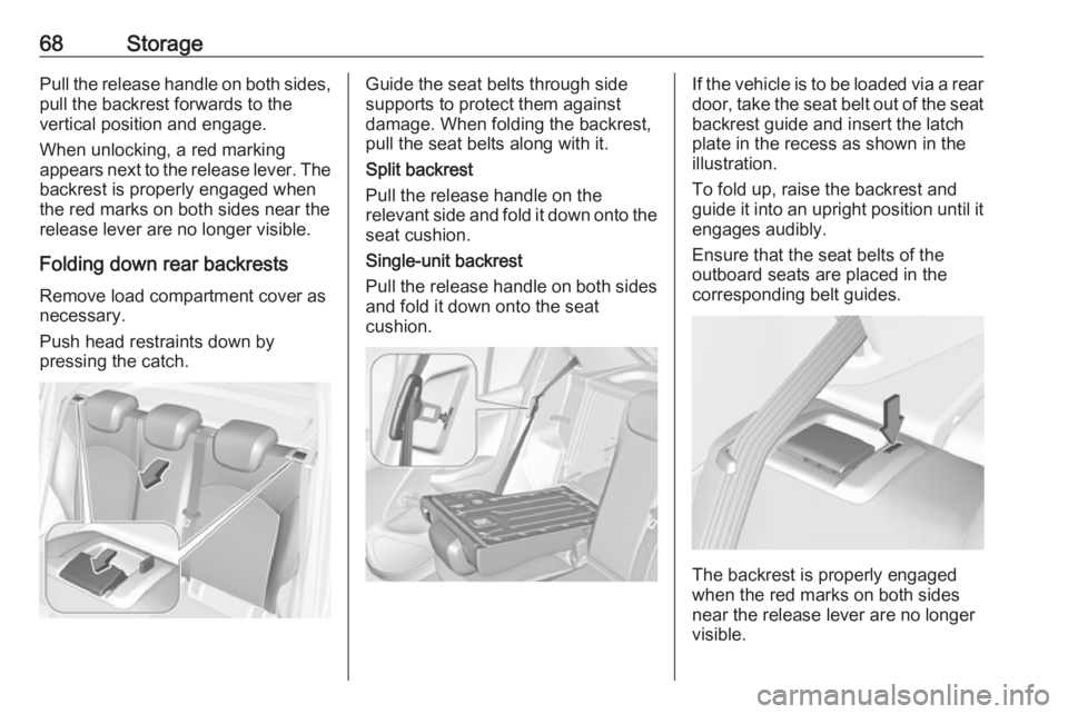
68StoragePull the release handle on both sides,
pull the backrest forwards to the
vertical position and engage.
When unlocking, a red marking
appears next to the release lever. The
backrest is properly engaged when
the red marks on both sides near the
release lever are no longer visible.
Folding down rear backrests Remove load compartment cover as
necessary.
Push head restraints down by
pressing the catch.Guide the seat belts through side
supports to protect them against
damage. When folding the backrest, pull the seat belts along with it.
Split backrest
Pull the release handle on the
relevant side and fold it down onto the seat cushion.
Single-unit backrest
Pull the release handle on both sides
and fold it down onto the seat
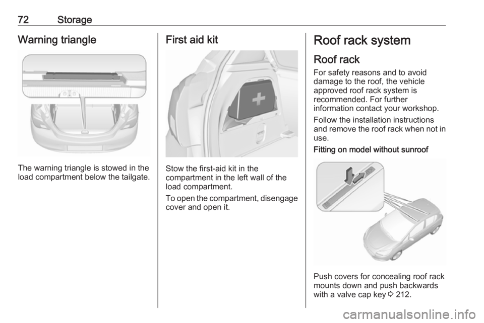
cushion.If the vehicle is to be loaded via a rear
door, take the seat belt out of the seat
backrest guide and insert the latch
plate in the recess as shown in the
illustration.
To fold up, raise the backrest and
guide it into an upright position until it engages audibly.
Ensure that the seat belts of the
outboard seats are placed in the corresponding belt guides.
The backrest is properly engaged
when the red marks on both sides
near the release lever are no longer
visible.
Page 71 of 269

Storage699Warning
Only drive the vehicle when the
backrests are securely locked into position. Otherwise there is a risk
of personal injury or damage to the
load or vehicle in the event of hard braking or a collision.
The seat belt of the centre seat could
be blocked when the backrest is
folded up too quickly. To unlock the
retractor, push in the seat belt or pull
it out by approx. 20 mm then release.
Load compartment cover
Do not place any objects on the cover.
3-door/5-door hatchback
Removing
Unhook retaining strings from
tailgate.
Lift cover at the rear and push it
upwards at the front.
Remove the cover.
Stowing
When the load compartment is fully
loaded, stow the load compartment
cover on the rear seats or remove
from vehicle.
Fitting
Engage cover in side guides and fold
downwards. Attach retaining strings
to tailgate.
Delivery vanThe load compartment cover consists
of four segments which can be
individually removed and inserted.
Removing
Page 72 of 269

70StorageTo remove rear cover, unhook
retaining strings from tailgate.
Lift cover at the rear and push it
upwards at the front. Remove the
cover.
To remove the three other segments
(order 1 to 3) lift at the rear,
disengage, twist and remove.
Fitting
Install the segments in the order 3 to
1. Engage segments in recesses at
the side.
The segments overlap at the
connecting points when they are
closed.
To install rear cover, engage cover in side guides and fold downwards.
Attach retaining strings to tailgate.
Rear floor storage cover
Rear floor cover
Lift up rear floor cover to gain access
to emergency breakdown equipment.
Tools 3 212.
In models with a tyre repair kit on the
right side in the load compartment,
the spare wheel recess may be used
as an additional stowage
compartment. Tyre repair kit 3 220.
Double load-bay floor
The double load-bay floor can be
inserted in the load compartment in
two positions:
● directly above the cover for the spare wheel recess or the floor
cover
● or in the upper openings in the load compartment
To remove, lift the load-bay floor
using the recess and pull backwards.
To insert, push the load-bay floor
forwards in the corresponding guide,
then lower.
Page 74 of 269

72StorageWarning triangle
The warning triangle is stowed in the
load compartment below the tailgate.
First aid kit
Stow the first-aid kit in the
compartment in the left wall of the
load compartment.
To open the compartment, disengage cover and open it.
Roof rack system
Roof rack For safety reasons and to avoid
damage to the roof, the vehicle
approved roof rack system is
recommended. For further
information contact your workshop.
Follow the installation instructions
and remove the roof rack when not in
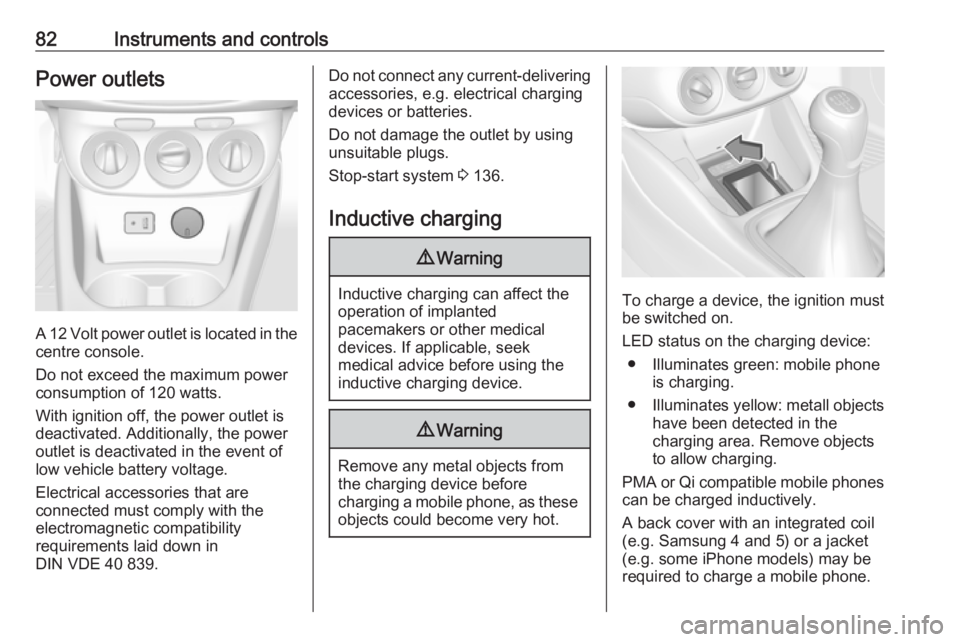
use.Fitting on model without sunroof
Push covers for concealing roof rack
mounts down and push backwards
with a valve cap key 3 212.
Page 75 of 269

Storage73Fitting on model with sunroof
Disengage covers concealing roof
rack mounts by pushing sliders in
direction of arrow and remove
upwards. To close roof rack mounts,
first insert covers at front and engage sliders at rear.
Attach roof rack at appropriate points, see enclosed roof rack system
instructions.
Loading information
● Heavy objects in the load compartment should be placed
against the seat backrests.
Ensure that the backrests are
securely engaged. If objects can
be stacked, heavier objects
should be placed at the bottom.
● Secure objects with lashing straps attached to the lashing
eyes 3 71.
● Use the hook at the right sidewall
of the load compartment for
hanging up carrier bags.
Maximum load: 5 kg.
● Secure loose objects in the load compartment to prevent themfrom sliding.
● When transporting objects in the load compartment, the backrestsof the rear seats must not be
angled forward.
● Do not allow the load to protrude above the upper edge of the
backrests.
● Do not place any objects on the load compartment cover or theinstrument panel, and do not
cover the sensor on top of the instrument panel.
● The load must not obstruct the operation of the pedals, parking
brake and gear selector lever, or
hinder the freedom of movement of the driver. Do not place any
unsecured objects in the interior.
● Do not drive with an open load compartment.
Page 84 of 269

82Instruments and controlsPower outlets
A 12 Volt power outlet is located in the
centre console.
Do not exceed the maximum power
consumption of 120 watts.
With ignition off, the power outlet is
deactivated. Additionally, the power outlet is deactivated in the event of
low vehicle battery voltage.
Electrical accessories that are
connected must comply with the
electromagnetic compatibility
requirements laid down in
DIN VDE 40 839.
Do not connect any current-delivering accessories, e.g. electrical charging
devices or batteries.
Do not damage the outlet by using
unsuitable plugs.
Stop-start system 3 136.
Inductive charging9 Warning
Inductive charging can affect the
operation of implanted
pacemakers or other medical
devices. If applicable, seek
medical advice before using the
inductive charging device.
9 Warning
Remove any metal objects from
the charging device before
charging a mobile phone, as these
objects could become very hot.
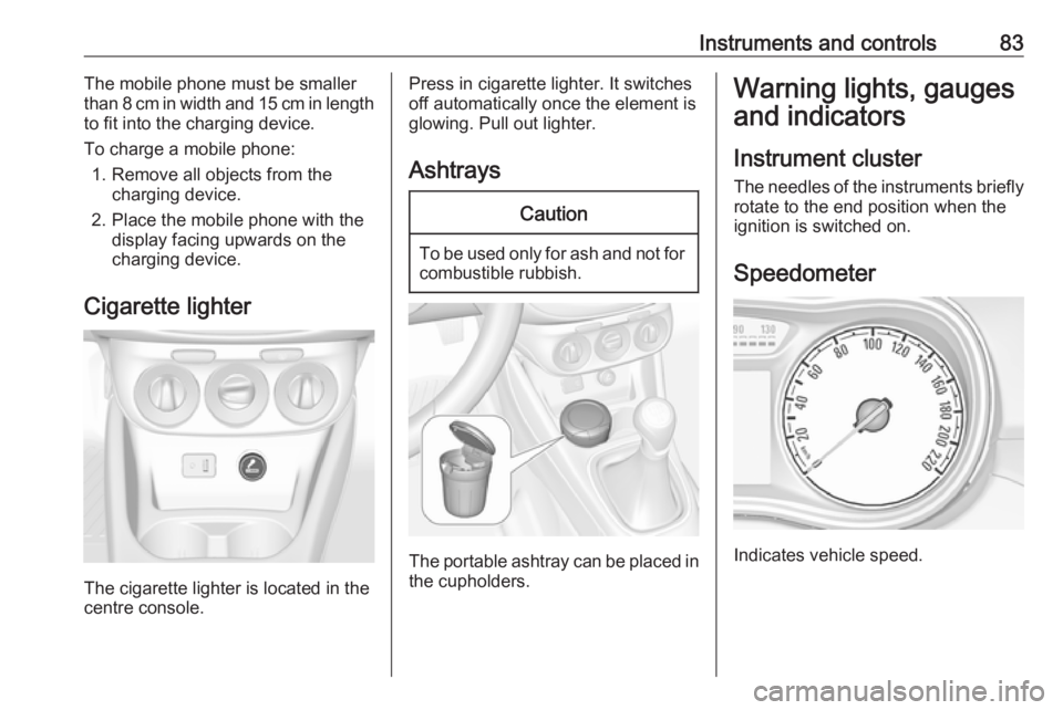
To charge a device, the ignition must
be switched on.
LED status on the charging device: ● Illuminates green: mobile phone is charging.
● Illuminates yellow: metall objects
have been detected in the
charging area. Remove objects
to allow charging.
PMA or Qi compatible mobile phones can be charged inductively.
A back cover with an integrated coil
(e.g. Samsung 4 and 5) or a jacket
(e.g. some iPhone models) may be
required to charge a mobile phone.
Page 85 of 269

Instruments and controls83The mobile phone must be smaller
than 8 cm in width and 15 cm in length
to fit into the charging device.
To charge a mobile phone: 1. Remove all objects from the charging device.
2. Place the mobile phone with the display facing upwards on the
charging device.
Cigarette lighter
The cigarette lighter is located in the
centre console.
Press in cigarette lighter. It switches off automatically once the element is
glowing. Pull out lighter.
AshtraysCaution
To be used only for ash and not for combustible rubbish.
The portable ashtray can be placed in
the cupholders.
Warning lights, gauges
and indicators
Instrument cluster
The needles of the instruments briefly
rotate to the end position when the
ignition is switched on.
Speedometer
Indicates vehicle speed.